JP2005517989A - Low slope dispersion shifted optical fiber - Google Patents
Low slope dispersion shifted optical fiber Download PDFInfo
- Publication number
- JP2005517989A JP2005517989A JP2003570164A JP2003570164A JP2005517989A JP 2005517989 A JP2005517989 A JP 2005517989A JP 2003570164 A JP2003570164 A JP 2003570164A JP 2003570164 A JP2003570164 A JP 2003570164A JP 2005517989 A JP2005517989 A JP 2005517989A
- Authority
- JP
- Japan
- Prior art keywords
- optical waveguide
- waveguide fiber
- refractive index
- wavelength
- region
- Prior art date
- Legal status (The legal status is an assumption and is not a legal conclusion. Google has not performed a legal analysis and makes no representation as to the accuracy of the status listed.)
- Pending
Links
Images


Classifications
-
- G—PHYSICS
- G02—OPTICS
- G02B—OPTICAL ELEMENTS, SYSTEMS OR APPARATUS
- G02B6/00—Light guides; Structural details of arrangements comprising light guides and other optical elements, e.g. couplings
- G02B6/02—Optical fibres with cladding with or without a coating
- G02B6/02004—Optical fibres with cladding with or without a coating characterised by the core effective area or mode field radius
- G02B6/02009—Large effective area or mode field radius, e.g. to reduce nonlinear effects in single mode fibres
-
- G—PHYSICS
- G02—OPTICS
- G02B—OPTICAL ELEMENTS, SYSTEMS OR APPARATUS
- G02B6/00—Light guides; Structural details of arrangements comprising light guides and other optical elements, e.g. couplings
- G02B6/02—Optical fibres with cladding with or without a coating
- G02B6/02214—Optical fibres with cladding with or without a coating tailored to obtain the desired dispersion, e.g. dispersion shifted, dispersion flattened
- G02B6/02219—Characterised by the wavelength dispersion properties in the silica low loss window around 1550 nm, i.e. S, C, L and U bands from 1460-1675 nm
- G02B6/02228—Dispersion flattened fibres, i.e. having a low dispersion variation over an extended wavelength range
- G02B6/02238—Low dispersion slope fibres
- G02B6/02242—Low dispersion slope fibres having a dispersion slope <0.06 ps/km/nm2
-
- G—PHYSICS
- G02—OPTICS
- G02B—OPTICAL ELEMENTS, SYSTEMS OR APPARATUS
- G02B6/00—Light guides; Structural details of arrangements comprising light guides and other optical elements, e.g. couplings
- G02B6/02—Optical fibres with cladding with or without a coating
- G02B6/02214—Optical fibres with cladding with or without a coating tailored to obtain the desired dispersion, e.g. dispersion shifted, dispersion flattened
- G02B6/02219—Characterised by the wavelength dispersion properties in the silica low loss window around 1550 nm, i.e. S, C, L and U bands from 1460-1675 nm
- G02B6/02266—Positive dispersion fibres at 1550 nm
- G02B6/02271—Non-zero dispersion shifted fibres, i.e. having a small positive dispersion at 1550 nm, e.g. ITU-T G.655 dispersion between 1.0 to 10 ps/nm.km for avoiding nonlinear effects
-
- G—PHYSICS
- G02—OPTICS
- G02B—OPTICAL ELEMENTS, SYSTEMS OR APPARATUS
- G02B6/00—Light guides; Structural details of arrangements comprising light guides and other optical elements, e.g. couplings
- G02B6/02—Optical fibres with cladding with or without a coating
- G02B6/036—Optical fibres with cladding with or without a coating core or cladding comprising multiple layers
- G02B6/03616—Optical fibres characterised both by the number of different refractive index layers around the central core segment, i.e. around the innermost high index core layer, and their relative refractive index difference
- G02B6/03638—Optical fibres characterised both by the number of different refractive index layers around the central core segment, i.e. around the innermost high index core layer, and their relative refractive index difference having 3 layers only
- G02B6/03644—Optical fibres characterised both by the number of different refractive index layers around the central core segment, i.e. around the innermost high index core layer, and their relative refractive index difference having 3 layers only arranged - + -
-
- G—PHYSICS
- G02—OPTICS
- G02B—OPTICAL ELEMENTS, SYSTEMS OR APPARATUS
- G02B6/00—Light guides; Structural details of arrangements comprising light guides and other optical elements, e.g. couplings
- G02B6/02—Optical fibres with cladding with or without a coating
- G02B6/036—Optical fibres with cladding with or without a coating core or cladding comprising multiple layers
- G02B6/03616—Optical fibres characterised both by the number of different refractive index layers around the central core segment, i.e. around the innermost high index core layer, and their relative refractive index difference
- G02B6/03661—Optical fibres characterised both by the number of different refractive index layers around the central core segment, i.e. around the innermost high index core layer, and their relative refractive index difference having 4 layers only
- G02B6/03666—Optical fibres characterised both by the number of different refractive index layers around the central core segment, i.e. around the innermost high index core layer, and their relative refractive index difference having 4 layers only arranged - + - +
-
- G—PHYSICS
- G02—OPTICS
- G02B—OPTICAL ELEMENTS, SYSTEMS OR APPARATUS
- G02B6/00—Light guides; Structural details of arrangements comprising light guides and other optical elements, e.g. couplings
- G02B6/02—Optical fibres with cladding with or without a coating
- G02B6/036—Optical fibres with cladding with or without a coating core or cladding comprising multiple layers
- G02B6/03616—Optical fibres characterised both by the number of different refractive index layers around the central core segment, i.e. around the innermost high index core layer, and their relative refractive index difference
- G02B6/03661—Optical fibres characterised both by the number of different refractive index layers around the central core segment, i.e. around the innermost high index core layer, and their relative refractive index difference having 4 layers only
- G02B6/03677—Optical fibres characterised both by the number of different refractive index layers around the central core segment, i.e. around the innermost high index core layer, and their relative refractive index difference having 4 layers only arranged - + + -
-
- G—PHYSICS
- G02—OPTICS
- G02B—OPTICAL ELEMENTS, SYSTEMS OR APPARATUS
- G02B6/00—Light guides; Structural details of arrangements comprising light guides and other optical elements, e.g. couplings
- G02B6/02—Optical fibres with cladding with or without a coating
- G02B6/036—Optical fibres with cladding with or without a coating core or cladding comprising multiple layers
- G02B6/03616—Optical fibres characterised both by the number of different refractive index layers around the central core segment, i.e. around the innermost high index core layer, and their relative refractive index difference
- G02B6/03688—Optical fibres characterised both by the number of different refractive index layers around the central core segment, i.e. around the innermost high index core layer, and their relative refractive index difference having 5 or more layers
-
- G—PHYSICS
- G02—OPTICS
- G02B—OPTICAL ELEMENTS, SYSTEMS OR APPARATUS
- G02B6/00—Light guides; Structural details of arrangements comprising light guides and other optical elements, e.g. couplings
- G02B6/02—Optical fibres with cladding with or without a coating
- G02B6/028—Optical fibres with cladding with or without a coating with core or cladding having graded refractive index
- G02B6/0286—Combination of graded index in the central core segment and a graded index layer external to the central core segment
-
- G—PHYSICS
- G02—OPTICS
- G02B—OPTICAL ELEMENTS, SYSTEMS OR APPARATUS
- G02B6/00—Light guides; Structural details of arrangements comprising light guides and other optical elements, e.g. couplings
- G02B6/02—Optical fibres with cladding with or without a coating
- G02B6/036—Optical fibres with cladding with or without a coating core or cladding comprising multiple layers
- G02B6/03605—Highest refractive index not on central axis
- G02B6/03611—Highest index adjacent to central axis region, e.g. annular core, coaxial ring, centreline depression affecting waveguiding
Abstract
中央領域及び2つ又は3つの環状領域を該中央領域とクラッド領域との間に含む低スロープ分散シフト光導波路ファイバである当該ファイバは、約1550nmの波長で約60μm2よりも小の実効面積と、約1430nmよりも小のゼロ分散波長と、約1550nmの波長で約4ps/nm/kmから約10ps/nm/kmの間の分散と、約1550nmの波長で0.045ps/nm2/kmよりも小の分散スロープと、約1260nmよりも小のケーブルカットオフ波長とを有する。The fiber, which is a low slope dispersion shifted optical waveguide fiber comprising a central region and two or three annular regions between the central region and the cladding region, has an effective area of less than about 60 μm 2 at a wavelength of about 1550 nm. A zero dispersion wavelength less than about 1430 nm, a dispersion between about 4 ps / nm / km and about 10 ps / nm / km at a wavelength of about 1550 nm, and 0.045 ps / nm 2 / km at a wavelength of about 1550 nm. Has a small dispersion slope and a cable cutoff wavelength of less than about 1260 nm.
Description
本出願は、2002年2月15日に出願された米国特許仮出願第60/357,539号の米国特許法第119条(e)に基づく優先権の利益を請求する。 This application claims the benefit of priority under 35 USC 119 (e) of US Provisional Application No. 60 / 357,539, filed February 15,2002.
本発明は、低スロープを有する非ゼロ分散シフト光ファイバ(NZDSF)に関する。より好ましくは、本発明は、低スロープ及び低ゼロ分散波長を有するNZDSFファイバに関する。 The present invention relates to a non-zero dispersion shifted optical fiber (NZDSF) having a low slope. More preferably, the present invention relates to NZDSF fiber having a low slope and a low zero dispersion wavelength.
1550nmの波長付近(本明細書中では、約1525nmから約1565nmの間の波長を含むCバンド及び約1565nmから約1625nmの間の波長を含むLバンドを含むものとして定義される)で動作する波長分割多重(WDM)システムがある。特定の既知のファイバが、動作窓の外側に位置するゼロ分散波長を有することで、4波混合(FWM)及び相互位相変調(XPM)の如き非線形ペナルティが防止され得る。しかしながら、既知のNZDSFファイバのかかるゼロ分散波長は、典型的には、1550nmで100nm以内である。そこで、1550nm動作窓内で伝送信号の分散の大きさを低減させることで、より長いスパン長及びより少ない回数の分散補償を許容するのである。 Wavelengths operating near the wavelength of 1550 nm (defined herein as including the C-band containing wavelengths between about 1525 nm and about 1565 nm and the L-band containing wavelengths between about 1565 nm and about 1625 nm) There are division multiplexing (WDM) systems. Certain known fibers have a zero dispersion wavelength located outside the operating window to prevent nonlinear penalties such as four-wave mixing (FWM) and cross-phase modulation (XPM). However, such zero dispersion wavelengths of known NZDSF fibers are typically within 100 nm at 1550 nm. Therefore, a longer span length and a smaller number of dispersion compensations are allowed by reducing the magnitude of the dispersion of the transmission signal within the 1550 nm operation window.
好ましくは、低密度波長分割多重(CWDM)システムやそのアプリケーションは、WDMの1550nm窓、即ち、Cバンド及びLバンド内、Sバンド(約1450nmから約1525nmの間)内、及び、1310nm窓(約1280nmから約1330nmの間)内で動作する。
Preferably, the low density wavelength division multiplexing (CWDM) system and its applications include
既知のファイバは、特定の窓内の動作に適した光学特性を有する。例えば、コーニング社によって製造されるSMF−28TM光ファイバの如き、標準単一モード伝送ファイバは、1310nm、または、その付近のゼロ分散波長を有する。かかるファイバは、1310nm窓内で好適に機能し得る。1550nmでかかる光ファイバが呈する分散は、約17ps/nm/kmであり、これは典型的なNZDSFファイバの1550nmでの分散よりも大であって、常分散補償を必要とし得る。NZDSF光ファイバは、1550nm窓内で好適に機能し得る。NZDSFの例は、1500nm付近で平均ゼロ分散波長及び約1550nmで約0.08ps/nm2/kmの分散スロープを有するコーニング社によるLEAF(登録商標)ファイバや、1590nm付近で平均ゼロ分散波長及び約1550nmで約0.1ps/nm2/kmの分散スロープを有するコーニング社によるサブマリンLEAF(登録商標)ファイバや、1650nm付近で平均ゼロ分散波長を有するコーニング社によるMetroCorTMファイバや、及び、約1450nmのゼロ分散波長を有するルーセント社によるTruewaveRSTMを含む。しかしながら、これらのNZDSF光ファイバの1310nm窓での分散の大きさは小さくなく、多数のNZDSF光ファイバは1260nmよりも大のケーブルカットオフ波長を示す。 Known fibers have optical properties that are suitable for operation within a particular window. For example, standard single mode transmission fibers, such as SMF-28 ™ optical fiber manufactured by Corning, have a zero dispersion wavelength at or near 1310 nm. Such fibers can work well within a 1310 nm window. The dispersion exhibited by such an optical fiber at 1550 nm is approximately 17 ps / nm / km, which is greater than the dispersion at 1550 nm of a typical NZDSF fiber and may require ordinary dispersion compensation. NZDSF optical fibers can work well within a 1550 nm window. Examples of NZDSF are LEAF® fibers from Corning with an average zero dispersion wavelength near 1500 nm and a dispersion slope of about 0.08 ps / nm 2 / km at about 1550 nm, and an average zero dispersion wavelength of about 1590 nm. Submarine LEAF® fiber from Corning with a dispersion slope of about 0.1 ps / nm 2 / km at 1550 nm, MetroCor ™ fiber from Corning with an average zero dispersion wavelength near 1650 nm, and about 1450 nm Includes Truewave RS ™ from Lucent with zero dispersion wavelength. However, the magnitude of the dispersion at the 1310 nm window of these NZDSF optical fibers is not small, and many NZDSF optical fibers exhibit cable cutoff wavelengths greater than 1260 nm.
本発明の1つの特徴は、約1550nmの波長で約60μm2よりも小なる実効面積、約1430nmよりも小なるゼロ分散波長、約1550nmの波長で約4ps/nm/kmから10ps/nm/kmの間にある分散、約1550nmの波長で0.045ps/nm2/kmよりも小なる分散スロープ、及び、約1260nmよりも小なるケーブルカットオフ波長を有する光導波路ファイバに関する。 One feature of the present invention is that the effective area is less than about 60 μm 2 at a wavelength of about 1550 nm, the zero dispersion wavelength is less than about 1430 nm, and about 4 ps / nm / km to about 10 ps / nm / km at a wavelength of about 1550 nm. And an optical waveguide fiber having a dispersion slope of less than 0.045 ps / nm 2 / km at a wavelength of about 1550 nm and a cable cutoff wavelength of less than about 1260 nm.
好ましくは、約1550nmの波長で実効面積が約58μm2よりも小であって、より好ましくは、約55μm2よりも小である。 Preferably, a smaller than the effective area at a wavelength of about 1550nm is about 58 .mu.m 2, more preferably smaller than about 55 .mu.m 2.
好ましくは、ゼロ分散波長は約1350nmから約1430nmの間にあり、より好ましくは、約1370nmから約1410nmの間にある。 Preferably, the zero dispersion wavelength is between about 1350 nm and about 1430 nm, more preferably between about 1370 nm and about 1410 nm.
好ましくは、約1550nmの波長で光ファイバの分散は約5ps/nm/kmから約9ps/nm/kmの間にあり、より好ましくは、約6ps/nm/kmから約8ps/nm/kmの間にある。 Preferably, at a wavelength of about 1550 nm, the dispersion of the optical fiber is between about 5 ps / nm / km and about 9 ps / nm / km, more preferably between about 6 ps / nm / km and about 8 ps / nm / km. It is in.
好ましくは、光ファイバの分散は約1530nmの波長で約3ps/nm/kmから約7ps/nm/kmの間にあって、より好ましくは、約1530nmの波長で約4ps/nm/kmから6ps/nm/kmの間にある。 Preferably, the dispersion of the optical fiber is between about 3 ps / nm / km and about 7 ps / nm / km at a wavelength of about 1530 nm, more preferably from about 4 ps / nm / km to 6 ps / nm / km at a wavelength of about 1530 nm. km.
約1550nmの波長で光ファイバの分散スロープは、好ましくは、0.042ps/nm2/kmよりも小であり、より好ましくは、約0.040ps/nm2/kmよりも小であり、更により好ましくは、約0.038ps/nm2/kmよりも小である。また分散スロープは、好ましくは、約1550nmの波長で約0.020ps/nm2/kmよりも大であり、より好ましくは、約1550nmの波長で0.030ps/nm2/kmよりも大である。 The dispersion slope of the optical fiber at a wavelength of about 1550 nm is preferably less than 0.042 ps / nm 2 / km, more preferably less than about 0.040 ps / nm 2 / km, and even more Preferably, it is less than about 0.038 ps / nm 2 / km. The dispersion slope is preferably at greater than about 0.020ps / nm 2 / km at a wavelength of about 1550nm, and more preferably, is greater than 0.030ps / nm 2 / km at a wavelength of about 1550nm .
好ましくは、光ファイバのケーブルカットオフ波長は約1240nmよりも小であり、より好ましくは、約1220nmよりも小であり、更により好ましくは1200nmよりも小である。理論的なカットオフ波長は、好ましくは、約1650nmよりも小で、より好ましくは、1630nmよりも小で、更により好ましくは、1610nmよりも小である。2m測定ファイバカットオフ波長は、好ましくは、1500nmよりも小である。好ましくは、基本モードカットオフ波長(LP01)は、約3500nmよりも大であり、より好ましくは、約4000nmよりも大である。 Preferably, the cable cutoff wavelength of the optical fiber is less than about 1240 nm, more preferably less than about 1220 nm, and even more preferably less than 1200 nm. The theoretical cutoff wavelength is preferably less than about 1650 nm, more preferably less than 1630 nm, and even more preferably less than 1610 nm. The 2 m measurement fiber cutoff wavelength is preferably less than 1500 nm. Preferably, the fundamental mode cutoff wavelength (LP01) is greater than about 3500 nm, more preferably greater than about 4000 nm.
約1310nmの波長での光導波路ファイバの分散は、好ましくは、ゼロよりも小であり、より好ましくは、0ps/nm/kmから約−7.5ps/nm/kmの間にあり、更により好ましくは、約0ps/nm/kmから約−6ps/nm/kmの間にある。ある好ましき実施例において、約1310nmの波長での分散は約0ps/nm/kmよりも小で、約−5ps/nm/kmよりも大である。他の好ましき実施例において、約1310nmの波長での分散は−4ps/nm/kmよりも小であり、かつ、約−7.5ps/nm/kmよりも大である。 The dispersion of the optical waveguide fiber at a wavelength of about 1310 nm is preferably less than zero, more preferably between 0 ps / nm / km and about −7.5 ps / nm / km, and even more preferably Is between about 0 ps / nm / km and about −6 ps / nm / km. In one preferred embodiment, the dispersion at a wavelength of about 1310 nm is less than about 0 ps / nm / km and greater than about −5 ps / nm / km. In other preferred embodiments, the dispersion at a wavelength of about 1310 nm is less than -4 ps / nm / km and greater than about -7.5 ps / nm / km.
好ましくは、約1550nmの波長での光導波路ファイバの減衰は0.23dB/kmよりも小であり、より好ましくは、0.22dB/kmよりも小であり、更により好ましくは、0.21dB/kmよりも小であり、より更により好ましくは、0.20dB/kmよりも小である。 Preferably, the attenuation of the optical waveguide fiber at a wavelength of about 1550 nm is less than 0.23 dB / km, more preferably less than 0.22 dB / km, and even more preferably 0.21 dB / km. less than km, even more preferably less than 0.20 dB / km.
約1383nmの波長での光導波路ファイバの減衰は、好ましくは、0.6dB/kmよりも小であり、より好ましくは、約0.5dB/kmよりも小であり、更により好ましくは、約0.4dB/kmである。ある好ましき実施例において、約1383nmの波長での減衰は、約1310nmの波長での減衰よりも約0.1dB/km程度大である。他の好ましき実施例において、約1383nmの波長での減衰は、約1310nmの波長での減衰よりも0.05dB/km程度大である。更に他の好ましき実施例において、約1383nmの波長での減衰は、約1310nmの波長での減衰程度である。その上他の更に好ましき実施例において、約1383nmの波長での減衰は、約1310nmの波長での減衰よりも小である。 The attenuation of the optical waveguide fiber at a wavelength of about 1383 nm is preferably less than 0.6 dB / km, more preferably less than about 0.5 dB / km, and even more preferably about 0. .4 dB / km. In one preferred embodiment, the attenuation at a wavelength of about 1383 nm is about 0.1 dB / km greater than the attenuation at a wavelength of about 1310 nm. In another preferred embodiment, the attenuation at a wavelength of about 1383 nm is about 0.05 dB / km greater than the attenuation at a wavelength of about 1310 nm. In yet another preferred embodiment, the attenuation at a wavelength of about 1383 nm is on the order of attenuation at a wavelength of about 1310 nm. In yet another more preferred embodiment, the attenuation at a wavelength of about 1383 nm is less than the attenuation at a wavelength of about 1310 nm.
好ましくは、約1550nmの波長での光ファイバの偏波モード分散は約0.1ps/km1/2よりも小であり、より好ましくは、約0.06ps/km1/2よりも小であり、更により好ましくは、約0.04ps/km1/2よりも小であり、その上更に好ましくは、約0.03ps/km1/2よりも小である。 Preferably, the polarization mode dispersion of the optical fiber at a wavelength of about 1550 nm is less than about 0.1 ps / km 1/2 , more preferably less than about 0.06 ps / km 1/2 . Even more preferably, it is less than about 0.04 ps / km 1/2 and even more preferably less than about 0.03 ps / km 1/2 .
光導波路ファイバは、好ましくは、約1600nmの波長で約25dB/kmよりも小であり、より好ましくは、約15dB/kmよりも小であり、更により好ましくは、10dB/kmよりも小であるピン配列曲げ損失を呈する。また、光導波路ファイバは、好ましくは、約1550nmの波長で約20dB/kmよりも小であり、より好ましくは、約15dB/kmよりも小であり、更により好ましくは、10dB/kmよりも小であるピン配列曲げ損失を呈する。 The optical waveguide fiber is preferably less than about 25 dB / km at a wavelength of about 1600 nm, more preferably less than about 15 dB / km, and even more preferably less than 10 dB / km. Presents pin array bending loss. Also, the optical waveguide fiber is preferably less than about 20 dB / km at a wavelength of about 1550 nm, more preferably less than about 15 dB / km, and even more preferably less than 10 dB / km. Presents a pin array bend loss.
好ましくは、本明細書に開示された光ファイバは、約1550nmの波長で、1.5dB/mよりも小であり、より好ましくは、1dB/mよりも小である側面荷重微小曲げ試験によって誘導される減衰を呈する。 Preferably, the optical fiber disclosed herein is guided by a side load microbending test at a wavelength of about 1550 nm, which is less than 1.5 dB / m, more preferably less than 1 dB / m. Exhibit attenuation.
好ましくは、光導波路ファイバが、中央線から外側へ放射状に延在し最大相対屈折率パーセント(Δ1,MAX)を持つ正の相対屈折率パーセント(Δ1%(r))を有する中央領域と、該中央領域を包囲し最小相対屈折率パーセント(Δ2,MIN)を持つ負の相対屈折率パーセント(Δ2%(r))を有する第1環状領域と、該第1環状領域を包囲し最大相対屈折率パーセント(Δ3,MAX)を持つ正の相対屈折率パーセント(Δ3%(r))を有する第2環状領域と、該第2環状領域を包囲し相対屈折率パーセント(Δc%(r))を有する外側環状クラッド領域とを含む。 Preferably, the optical waveguide fiber has a positive relative refractive index percentage (Δ 1 % (r)) having a maximum relative refractive index percentage (Δ 1, MAX ) extending radially outward from the center line and A first annular region having a negative relative refractive index percentage (Δ 2 % (r)) surrounding the central region and having a minimum relative refractive index percent (Δ 2, MIN ), and surrounding the first annular region A second annular region having a positive relative refractive index percent (Δ 3 % (r)) having a maximum relative refractive index percent (Δ 3, MAX ); and a relative refractive index percent (Δ c) surrounding the second annular region. % (R)) outer annular cladding region.
好ましくは、該第1環状領域は、該中央領域に隣接する。好ましくは、該第2環状領域は、該第1環状領域に隣接する。 Preferably, the first annular region is adjacent to the central region. Preferably, the second annular region is adjacent to the first annular region.
好ましくは、Δ1,MAXは約0.4%から0.7%の間にあって、より好ましくは、Δ1,MAXは約0.45%から0.65%の間にある。好ましき実施例において、Δ1,MAXは約0.5%から0.65%の間にある。 Preferably, Δ1 , MAX is between about 0.4% and 0.7%, and more preferably, Δ1 , MAX is between about 0.45% and 0.65%. In the preferred embodiment, Δ 1, MAX is between about 0.5% and 0.65%.
該中央領域は、好ましくは、約3μmから約6μmの間の半径まで延在し、より好ましくは、約3μmから約5μmの間の半径まで延在する。 The central region preferably extends to a radius between about 3 μm and about 6 μm, and more preferably extends to a radius between about 3 μm and about 5 μm.
好ましくは、該中央領域は、約1から約6の間のアルファ、より好ましくは、約2から約4の間のアルファを有する。 Preferably, the central region has an alpha between about 1 and about 6, more preferably between about 2 and about 4.
好ましくは、Δ2,MINは、約−0.05%から−0.35%の間にあって、より好ましくは、約−0.1%から約−0.30%の間にあって、最も好ましくは、約−0.14%から約−0.25%の間にある。好ましくは、Δ1,MAXからΔ2,MINの間の差の絶対値は、約0.45%から約1.05%の間にあって、より好ましくは、約0.55%から約0.95%の間にある。 Preferably, Δ 2, MIN is between about −0.05% and −0.35%, more preferably between about −0.1% and about −0.30%, most preferably Between about -0.14% and about -0.25%. Preferably, the absolute value of the difference between Δ1 , MAX and Δ2 , MIN is between about 0.45% and about 1.05%, more preferably from about 0.55% to about 0.95. % Is between.
該第1環状領域は、好ましくは、該中央領域を包囲し、5μmから約9μmの間の半径まで延在し、より好ましくは、6μmから約8μmの間の半径まで延在し、最も好ましくは、約3.5μmから約7.5μmの間の半径まで延在する。好ましくは、該第1環状領域の少なくとも一部分が4μmの半径から約8μmの半径の間に配置される。 The first annular region preferably surrounds the central region and extends to a radius between 5 μm and about 9 μm, more preferably extends to a radius between 6 μm and about 8 μm, most preferably , Extending to a radius between about 3.5 μm and about 7.5 μm. Preferably, at least a portion of the first annular region is disposed between a radius of 4 μm and a radius of about 8 μm.
該第1環状領域は好ましくは約1.5μmから約4.5μmの間の幅、より好ましくは、約2μmから4μmの間の幅を有する。 The first annular region preferably has a width between about 1.5 μm and about 4.5 μm, more preferably a width between about 2 μm and 4 μm.
好ましくは該第1環状領域は約4μmから約6.5μmの間の中間点、より好ましくは、約4.5μmから約6μmの間の中間点を有する。 Preferably, the first annular region has an intermediate point between about 4 μm and about 6.5 μm, more preferably an intermediate point between about 4.5 μm and about 6 μm.
好ましくは、Δ3,MAXは、約0.1%から0.3%の間にあって、より好ましくは、約0.15%から0.3%の間にある。好ましくは、Δ1,MAXからΔ3,MAXの間の差は、約0.1%から約0.6%の間にあって、より好ましくは、約0.15%から約0.5%の間にある。好ましくは、Δ1,MAXはΔ3,MAXよりも大である。 Preferably, Δ 3, MAX is between about 0.1% and 0.3%, more preferably between about 0.15% and 0.3%. Preferably, the difference between the Δ 1, MAX Δ 3, MAX is be between about 0.1% to about 0.6%, more preferably, between about 0.15% to about 0.5% It is in. Preferably, Δ 1, MAX is greater than Δ 3, MAX .
該第2環状領域は、好ましくは、該第1環状領域を包囲し、約9μmから約15μmの間の半径まで延在し、より好ましくは、約10μmから約14μmの間の半径まで延在する。 The second annular region preferably surrounds the first annular region and extends to a radius between about 9 μm and about 15 μm, and more preferably extends to a radius between about 10 μm and about 14 μm. .
該第2環状領域は、約2μmから約8μmの間の幅、より好ましくは、約3μmから約7μmの間の幅を有する。該第2環状領域は、好ましくは、約3μmから約9μmの間の半値幅、より好ましくは、約3.5μmから約8.5μmの間の半値幅、更により好ましくは、約4μmから約8μmの間の半値幅を有する。該半値幅の中間点は、約7.5μmから約10.5μmの間にあって、より好ましくは、約8μmから約10μmの間にある。 The second annular region has a width between about 2 μm and about 8 μm, more preferably between about 3 μm and about 7 μm. The second annular region preferably has a half width between about 3 μm and about 9 μm, more preferably a half width between about 3.5 μm and about 8.5 μm, even more preferably between about 4 μm and about 8 μm. With a full width at half maximum. The midpoint of the full width at half maximum is between about 7.5 μm and about 10.5 μm, more preferably between about 8 μm and about 10 μm.
いくつかの好ましき実施例において、該光導波路ファイバは第2環状領域を包囲し該第2環状領域と外側環状クラッド領域との間に配置され、最小相対屈折率パーセント(Δ4,MIN)を持つ負の相対屈折率パーセント(Δ4%(r))を有する第3環状領域を含む。好ましくは、該第3環状領域は該第2環状領域に隣接する。好ましくは、該光ファイバは第3環状領域を有し、Δ2,MINは、好ましくは、約−0.05%から−0.3%の間にあって、より好ましくは、約−0.1から−0.25%の間にある。 In some preferred embodiments, the optical waveguide fiber surrounds a second annular region and is disposed between the second annular region and the outer annular cladding region, and has a minimum relative refractive index percentage (Δ 4, MIN ). And a third annular region having a negative relative refractive index percent (Δ 4 % (r)). Preferably, the third annular region is adjacent to the second annular region. Preferably, the optical fiber has a third annular region and Δ 2, MIN is preferably between about −0.05% and −0.3%, more preferably from about −0.1. It is between -0.25%.
いくつかの好ましき実施例において、Δ2,MINはΔ4,MINよりも大である。他の好ましき実施例において、Δ2,MINはΔ4,MINよりも小である。更に他の好ましき実施例において、Δ2,MINはΔ4,MINとほぼ等しい。 In some preferred embodiments, Δ 2, MIN is greater than Δ 4, MIN . In other preferred embodiments, Δ 2, MIN is less than Δ 4, MIN . In yet another preferred embodiment, Δ 2, MIN is approximately equal to Δ 4, MIN .
該第3環状領域は、好ましくは、約9μmから約15μmの間の半径から12μmから約20μmの間の半径まで延在する。より好ましくは、該第3環状領域は、約10μmから約14μmの間の半径から13μmから約18μmの間の半径まで延在する。 The third annular region preferably extends from a radius between about 9 μm and about 15 μm to a radius between 12 μm and about 20 μm. More preferably, the third annular region extends from a radius between about 10 μm and about 14 μm to a radius between 13 μm and about 18 μm.
好ましくは、該第3環状領域は、約1.5μmから約7μmの間の幅、より好ましくは、約2μmから約6μmの間の幅を有する。 Preferably, the third annular region has a width between about 1.5 μm and about 7 μm, more preferably between about 2 μm and about 6 μm.
好ましくは、該第3環状領域は、約11μmから約18μmの間の幅、より好ましくは、約12μmから約16μmの間の中間点を有する。 Preferably, the third annular region has a width between about 11 μm and about 18 μm, more preferably an intermediate point between about 12 μm and about 16 μm.
好ましくは、該中央領域はダウンドーパントを含まない。 Preferably, the central region does not contain downdopants.
本発明の他の特徴は、中央領域と、該中央領域を包囲する第1環状領域と、該第1環状領域を包囲する第2環状領域と、及び、該第2環状領域を包囲する外側環状クラッド領域とを含む光導波路プリフォームに関する。該外側環状クラッド領域は、最小半径(rc,min)を有する。該中央領域は、好ましくは、約0.2から約0.45の間の規格化された最大半径(r1/rc,min)を有し、該第1環状領域は、好ましくは、約0.3から約0.65の間の規格化された最大半径(r2/rc,min)を有する。 Other features of the present invention include a central region, a first annular region surrounding the central region, a second annular region surrounding the first annular region, and an outer ring surrounding the second annular region. The present invention relates to an optical waveguide preform including a cladding region. The outer annular cladding region has a minimum radius (r c, min ). The central region preferably has a normalized maximum radius (r 1 / r c, min ) between about 0.2 and about 0.45, and the first annular region is preferably about It has a standardized maximum radius (r 2 / r c, min ) between 0.3 and about 0.65.
該光導波路プリフォームは、更に、該第2環状領域と該外側環状クラッドとの間に配置される第3環状領域を有し得る。好ましくは、該外側環状クラッド領域は該第3環状領域に隣接する。 The optical waveguide preform may further include a third annular region disposed between the second annular region and the outer annular cladding. Preferably, the outer annular cladding region is adjacent to the third annular region.
該中央領域、第1,第2,及び、第3環状領域の相対屈折率分布は、本明細書に開示された該光ファイバの分布に対応する。好ましくは、該中央領域は約0.2から約0.3の間の規格化された最大半径(r1/rc,min)を有し、該第1環状領域は約0.35から約0.55の間の規格化された最大半径(r2/rc,min)を有し、該第2環状領域は約0.7から約0.85の間の規格化された最大半径(r3/rc,min)を有する。 The relative refractive index distribution of the central region, the first, second, and third annular regions corresponds to the distribution of the optical fiber disclosed herein. Preferably, the central region has a normalized maximum radius (r 1 / r c, min ) between about 0.2 and about 0.3, and the first annular region is about 0.35 to about 0.3. Having a normalized maximum radius (r 2 / r c, min ) of between 0.55 and the second annular region having a normalized maximum radius of between about 0.7 and about 0.85 ( r 3 / r c, min ).
好ましくは、本明細書に記載され開示された該光ファイバは、約1260nmから約1650nmの間の複数の動作波長窓で、好適な性能を与える。より好ましくは、本明細書に記載され開示された該光ファイバは、約1260nmから約1650nmまでの複数の波長で好適な性能を与える。好ましき実施例において、本明細書に記載され開示された該光ファイバは、少なくとも1310nm窓及び1550nm窓で動作を適応させ得る2つの窓ファイバである。 Preferably, the optical fiber described and disclosed herein provides suitable performance at a plurality of operating wavelength windows between about 1260 nm and about 1650 nm. More preferably, the optical fiber described and disclosed herein provides suitable performance at multiple wavelengths from about 1260 nm to about 1650 nm. In a preferred embodiment, the optical fiber described and disclosed herein is a two window fiber that can accommodate operation with at least a 1310 nm window and a 1550 nm window.
参照は、現在、本発明の現在の好ましき実施例、添付図面に説明される例によって、詳細にされるであろう。本発明によるセグメントコア相対屈折率分布の典型的な実施例はそれぞれの図面に示されている。 Reference will now be made in detail to the presently preferred embodiments of the invention, examples illustrated in the accompanying drawings. An exemplary embodiment of the segment core relative refractive index profile according to the present invention is shown in the respective drawings.
本発明の更なる特徴及び効果は、この後に続く発明の詳細な説明に記載され、当業者であればこの発明の詳細な説明の記載から明らかであろうが、特許請求の範囲及び添付図面とともに後に続く記述に記載された発明を実施することによっても認識されるであろう。 Additional features and advantages of the invention will be set forth in the detailed description of the invention that follows, and will be apparent to those skilled in the art from the description of the detailed description of the invention, together with the claims and accompanying drawings. It will also be appreciated by practicing the invention described in the description that follows.
「屈折率分布」は、屈折率又は相対屈折率と導波路ファイバ半径との関係である。 “Refractive index profile” is the relationship between refractive index or relative refractive index and waveguide fiber radius.
「相対屈折率パーセント」は、 "Relative refractive index percentage"
![]()
![]()
と定義され、ここで、niは特に断りがない限り領域iにおける最大屈折率であり、ncはクラッド領域の平均屈折率である。環状領域又はセグメントの屈折率がクラッド領域の平均屈折率よりも小である場合において、相対屈折率パーセントが負であり、低下した領域又は低下した屈折率を有することを示し、特に断りがない限り屈折率が最も負である点で計算される。環状領域又はセグメントの屈折率がクラッド領域の平均屈折率よりも大である場合において、相対屈折率パーセントが正であり、かかる領域が高い又は正の屈折率を有していると言える。「ダウンドーパント」が、本明細書では、ドープされていない純SiO2と比較して屈折率を低くする傾向を有するドーパントとして考えられる。ダウンドーパントが、ダウンドーパントではない1つ又は複数の他のドーパントとともに、正の相対屈折率を有する光ファイバの領域に存在し得る。同様に、ダウンドーパントでない1つ又は複数の他のドーパントが負の相対屈折率を有する光ファイバの領域に存在し得る。 It is defined as, where, n i is the particular maximum refractive index in region i, unless otherwise specified, n c is the average refractive index of the cladding region. Unless the refractive index of the annular region or segment is less than the average refractive index of the cladding region, the relative refractive index percentage is negative, indicating that it has a reduced region or a reduced refractive index, unless otherwise noted. Calculated at the point where the refractive index is the most negative. When the refractive index of the annular region or segment is greater than the average refractive index of the cladding region, the relative refractive index percentage is positive and it can be said that such a region has a high or positive refractive index. A “downdopant” is considered herein as a dopant that has a tendency to lower the refractive index compared to pure undoped SiO 2 . A downdopant may be present in a region of an optical fiber having a positive relative refractive index, along with one or more other dopants that are not downdopants. Similarly, one or more other dopants that are not downdopants may be present in the region of the optical fiber having a negative relative refractive index.
本明細書では特に断りがない限り「分散」として示される導波路ファイバの「色分散」は、材料分散、導波路分散、及び、内部モード(インターモーダル)分散の和である。単一モード導波路ファイバの場合は、内部モード分散は、ゼロである。 In this specification, unless otherwise specified, “chromatic dispersion” of a waveguide fiber indicated as “dispersion” is the sum of material dispersion, waveguide dispersion, and internal mode (intermodal) dispersion. For a single mode waveguide fiber, the internal mode dispersion is zero.
実効面積は、 Effective area is
![]()
![]()
と定義され、ここで、積分範囲は0から∞であり、Eは導波路内の光伝搬に関連した電場である。 Where the integration range is from 0 to ∞, and E is the electric field associated with light propagation in the waveguide.
「α分布」という用語は、屈折率分布を示し、Δ(r)%で表現され(ここでrは半径である)、次の式で表される。 The term “α distribution” indicates a refractive index distribution, which is expressed by Δ (r)% (where r is a radius), and is expressed by the following formula.
![]()
![]()
ここで、r0はΔ(r)%が最大である点であり、r1はΔ(r)%がゼロの点であり、rはri≦r≦rfであり、Δは上記の如く定義され、riはα分布の最初の点であり、rfはα分布の最後の点であり、αは実数の指数である。 Here, r 0 is the point where Δ (r)% is maximum, r 1 is the point where Δ (r)% is zero, r is r i ≦ r ≦ r f , and Δ is Where r i is the first point of the α distribution, r f is the last point of the α distribution, and α is a real exponent.
モードフィールド径(MFD)はピータマンII法を使用して測定される。かかる方法は、次の式で示される。 Mode field diameter (MFD) is measured using the Peterman II method. Such a method is represented by the following equation.
![]()
![]()
![]()
![]()
ここで、積分範囲は0から∞までである。 Here, the integration range is from 0 to ∞.
導波路ファイバの曲げ抵抗が規定された試験条件の下に誘導される減衰によって評価され得る。 The bending resistance of the waveguide fiber can be evaluated by attenuation induced under defined test conditions.
曲げ試験の1つのタイプは、側面荷重微小曲げ試験である。このいわゆる「側面荷重」試験において、規定された長さの導波路ファイバが2つの平面プレートの間に置かれる。70番のワイヤーメッシュがかかるプレートの1つに取り付けられる。既知の長さの導波路ファイバがかかるプレートの間に挟まれ、プレートが互いに30Nの力で押される間に基準減衰が測定される。70Nの力がプレートに与えられ、減衰の増加がdB/mで測定される。減衰の増加は、導波路の側面荷重減衰である。 One type of bending test is a side load microbending test. In this so-called “side load” test, a defined length of waveguide fiber is placed between two planar plates. A No. 70 wire mesh is attached to one such plate. A known length of waveguide fiber is sandwiched between such plates, and the reference attenuation is measured while the plates are pressed together with a force of 30N. A force of 70 N is applied to the plate and the increase in attenuation is measured in dB / m. The increase in attenuation is the side load attenuation of the waveguide.
「ピン配列」曲げ試験は、曲げによる導波路ファイバの相対抵抗を比較するために使用される。この試験を行うために、減衰損失が本質的に誘導曲げ損失のない導波路ファイバに対して測定される。その後、導波路ファイバがピン配列を通って組み入れられ、減衰が再び測定される。曲げによって誘導される損失は、この2つの測定された減衰の差である。ピン配列は、1列に並べられた10本の円筒状のピンのセットであり、平らな表面上に鉛直に固定されている。ピン間隔は中心と中心との間で5mmである。ピンの直径は0.67mmである。試験の間、十分な張力が印加され、導波路ファイバがピン表面の一部分に適合する。 The “pin array” bend test is used to compare the relative resistance of waveguide fibers due to bending. To perform this test, attenuation loss is measured for a waveguide fiber that is essentially free of induced bending loss. A waveguide fiber is then incorporated through the pin array and attenuation is measured again. The loss induced by bending is the difference between the two measured attenuations. The pin array is a set of ten cylindrical pins arranged in a row, and is fixed vertically on a flat surface. The pin spacing is 5 mm between the centers. The pin diameter is 0.67 mm. During testing, sufficient tension is applied and the waveguide fiber conforms to a portion of the pin surface.
定められたモードに対する、理論的なファイバカットオフ波長もしくは「理論的なファイバカットオフ」もしくは「理論的なカットオフ」は、それより上では誘導された光がかかるモードで伝搬できない波長である。1990年ニューヨークのJeunhomme社から刊行された「Single Mode Fiber Optics」の第39乃至44頁のMercel Dekker氏の記載において、数学的な定義では、理論的なファイバカットオフは、モード伝搬定数が外側クラッドにおける平面波伝搬定数と等しくなる波長として記載されている。この理論的な波長は、直径が変化しない、無限に長い、完全に真っ直ぐなファイバに対して当てはまる。 The theoretical fiber cutoff wavelength or “theoretical fiber cutoff” or “theoretical cutoff” for a given mode is the wavelength above which guided light cannot propagate in such a mode. In the description of Mercel Dekker, pages 39-44 of “Single Mode Fiber Optics” published by Jeunhomme in New York in 1990, the theoretical fiber cutoff is that the mode propagation constant is the outer cladding. Is described as a wavelength equal to the plane wave propagation constant in FIG. This theoretical wavelength is true for infinitely long, perfectly straight fibers that do not change in diameter.
実効ファイバカットオフは、曲げ及び/又は機械的圧力に誘導される損失のため、理論的なカットオフより低い。この状況では、かかるカットオフがより高いLP11及びLP02モードを示す。LP11及びLP02は、一般に、測定では区別されず、スペクトル測定のステップとして明らかになる。即ち、測定されたカットオフより長い波長のモードは観測されない。実際のファイバカットオフは、「2mファイバカットオフ」もしくは「測定されたカットオフ」としても知られる「ファイバカットオフ波長」をもたらす標準2mファイバカットオフ試験(FOTP−80(EIA−TIA−455−80))によって測定され得る。FOTP−80標準試験は、制御された量の曲げを使用する高次モードを無視するか、かかるファイバのスペクトル応答をマルチモードファイバのスペクトル応答に規格化するかして行われる。 The effective fiber cutoff is lower than the theoretical cutoff because of losses induced by bending and / or mechanical pressure. In this situation, LP11 and LP02 modes with higher cut-off are shown. LP11 and LP02 are generally not distinguished in the measurement and become apparent as a step of spectrum measurement. That is, no mode with a wavelength longer than the measured cutoff is observed. The actual fiber cut-off is the standard 2 m fiber cut-off test (FOTP-80 (EIA-TIA-455-) that results in a “fiber cut-off wavelength”, also known as “2 m fiber cut-off” or “measured cut-off”. 80)). The FOTP-80 standard test is performed by ignoring higher order modes that use a controlled amount of bending or by normalizing the spectral response of such a fiber to the spectral response of a multimode fiber.
ケーブルカットオフ波長(もしくは「ケーブルカットオフ」)は、ケーブル環境におけるより高いレベルの曲げ及び機械的圧力のため、測定されたファイバカットオフよりも更に低い。実際のケーブル状態は、EIA−445ファイバ光学試験手順に記載されるケーブルカットオフ試験によって近似され得る。該手順は、EIA−TIAファイバ光学標準(電子工業連合−遠距離通信工業協会ファイバ光学標準、一般にはFOTP’sとして知られる)の一部である。ケーブルカットオフ測定は、送信出力による単一モードファイバのEIA−455−170ケーブルカットオフ波長(又は「FOTP−170」)に記載されている。 The cable cutoff wavelength (or “cable cutoff”) is even lower than the measured fiber cutoff due to higher levels of bending and mechanical pressure in the cable environment. The actual cable condition can be approximated by a cable cut-off test described in the EIA-445 fiber optic test procedure. The procedure is part of the EIA-TIA fiber optic standard (Electronic Industries Union-Telecommunication Industry Association fiber optic standard, commonly known as FOTP's). Cable cut-off measurements are described in EIA-455-170 cable cut-off wavelength (or “FOTP-170”) for single mode fiber with transmit power.
導波路ファイバ遠距離通信リンク、もしくは、単にリンクは、光信号の送信機、光信号の受信機、及び、相互に光信号を伝搬する送信機及び受信機に光学的に結合された各端部を有する一定長の単数もしくは複数のファイバから組み立てられる。かかる一定長の導波路ファイバは、直列に並べられて、端部と端部を互いに結合又は連結された複数のより短い長さのファイバから作られ得る。リンクは、光学増幅器、光学減衰器、光学アイソレータ、光学スイッチ、光学フィルタ、又は、多重化又は逆多重化デバイスの如き更なる光学コンポーネントを含み得る。内部連結リンクのグループは、遠距離通信システムを意味する。 A waveguide fiber telecommunications link, or simply a link, is an optical signal transmitter, an optical signal receiver, and ends that are optically coupled to a transmitter and receiver that propagate optical signals to each other. Are assembled from a single or multiple fibers of fixed length. Such a length of waveguide fiber may be made from a plurality of shorter length fibers arranged in series and coupled or connected end to end. The link may include additional optical components such as optical amplifiers, optical attenuators, optical isolators, optical switches, optical filters, or multiplexing or demultiplexing devices. A group of interconnected links refers to a telecommunications system.
本明細書に使用される光ファイバのスパンは、光デバイスの間(例えば2つの光増幅器の間、又は、多重化デバイスと光増幅器の間)に延在する、一定長の光ファイバ、又は、連続的に結合した複数の光ファイバを含む。スパンは、本明細書に開示された1つ又は複数の部分の光ファイバを含み得て、更に、例えばスパンの端部での残余分散の如き所望のシステム性能又はパラメータを達成すべく選択される1つ又は複数の他の光ファイバを含み得る。 As used herein, a span of optical fiber is a length of optical fiber that extends between optical devices (eg, between two optical amplifiers, or between a multiplexing device and an optical amplifier), or It includes a plurality of optical fibers coupled in series. The span may include one or more portions of the optical fiber disclosed herein and is further selected to achieve a desired system performance or parameter, such as residual dispersion at the end of the span, for example. One or more other optical fibers may be included.
一般に、光ファイバの「物理的」コアは、ドープされ得る1つ又は複数のセグメントを含む。かかるセグメントは、コアの物理的に同定できる部分である。同時に、光学的に言う「光学的」コアは、本明細書において、約99%の伝搬光が光ファイバ内を伝搬し、一部の伝搬光が物理コアセグメントの外側を伝搬することを考慮されていることを理解されるべきである。 In general, the “physical” core of an optical fiber includes one or more segments that can be doped. Such a segment is a physically identifiable part of the core. At the same time, an “optical” core that is optically referred to herein is considered to account for about 99% of the propagating light propagating within the optical fiber and some propagating light propagating outside the physical core segment. Should be understood.
好ましくは、本明細書に開示されたファイバが気相蒸着法によって製造される。更により好ましくは、本明細書に開示されたファイバが外付け気相蒸着法(OVD)によって製造される。このように、例えば、既知のOVDレイダウン、圧密化、及び、線引き技術が本明細書に開示された光導波路ファイバを製造するために好適に使用され得る。内付け化学気相蒸着法(MCVD)又は気相軸付け法(VAD)の如き他の処理が使用され得る。このように、本明細書に開示された光導波ファイバの屈折率及び断面分布はこれらに限定されないが、OVD、VAD、及び、MCVD処理を含む当業者に既知の製造技術を使用して、達成され得る。 Preferably, the fibers disclosed herein are manufactured by vapor deposition. Even more preferably, the fibers disclosed herein are manufactured by external vapor deposition (OVD). Thus, for example, known OVD laydown, consolidation, and drawing techniques can be suitably used to manufacture the optical waveguide fiber disclosed herein. Other processes such as internal chemical vapor deposition (MCVD) or gas phase axial (VAD) can be used. Thus, the refractive index and cross-sectional distribution of the optical waveguide fiber disclosed herein can be achieved using manufacturing techniques known to those skilled in the art including, but not limited to, OVD, VAD, and MCVD processes. Can be done.
図1は、中央領域(もしくは、第1コアセグメント)4、該中央領域4に隣接し且つこれを包囲する第1環状領域(もしくは第2コアセグメント)6、該第1環状領域6に隣接し且つこれを包囲する第2環状領域(もしくは第3コアセグメント)8、及び、該第2環状領域8に隣接し且つこれを包囲する外側環状クラッド領域もしくはクラッドもしくはクラッド層14を有する本発明による光導波路ファイバ2の概略図(スケール通りではない)である。
FIG. 1 shows a central region (or first core segment) 4, a first annular region (or second core segment) 6 adjacent to and surrounding the
図2は、中央領域(もしくは第1コアセグメント)4、該中央領域4に隣接し且つこれを包囲する第1環状領域(もしくは第2コアセグメント)6、該第1環状領域6に隣接し且つこれを包囲する第2環状領域(もしくは第3コアセグメント)8、該第2環状領域8に隣接し且つこれを包囲する第3環状領域(もしくは第4コアセグメント)10、及び、該第3環状領域10に隣接し且つこれを包囲する外側環状クラッド領域又はクラッド又はクラッド層14を有する本発明による第2光導波路ファイバ3の概略図(スケール通りではない)である。
FIG. 2 shows a central region (or first core segment) 4, a first annular region (or second core segment) 6 adjacent to and surrounding the
好ましくは、本明細書に開示された光ファイバのクラッド14は、純粋又は実質的に純粋なシリカである。より好ましくは、該クラッドはその中にゲルマニア又はフッ素ドーパントを含まない。該外側環状クラッド領域14は、例えばレイダウン工程の間、堆積された、又は、チューブ・イン・ロッド光プリフォーム配列におけるチューブ又は堆積された材料と被覆との組み合わせの如き、被覆の形成において提供されるクラッド材料からなり得る。該外側環状クラッド領域14は、1つ又は複数のドーパントを含み得る。該クラッド14は第1コーティング及び第2コーティングSによって包囲される。該クラッド14の屈折率が本明細書内の他の場所で議論される場合と同様に相対屈折率パーセントを計算するために使用される。
Preferably, the
図面を参照すると、該クラッド層14は、Δ%(r)=0を有して定義されるコアを包囲する屈折率ncを有し、光ファイバ又は光ファイバプリフォームの複数の部分又は領域の屈折率パーセントを計算するために使用される。
Referring to the drawings, the
中央コア領域又はコア領域の如き領域の分布の記載において、最大点の半分は、Δ1,MAXの如きピーク屈折率(もしくは最大屈折率)を決定することによって定義され得る。また、Δ1,MAXの如きピーク屈折率(もしくは最大屈折率)の値の半分と等しい相対屈折率に対応する半径を決定することによって定義され得る。即ち、半径に対する相対屈折率が描く曲線から垂下された垂線がΔ%(r)=0(即ち、クラッド層の相対屈折率)を横切る位置を決定することによって定義される。 In describing the distribution of a region such as the central core region or core region, half of the maximum point can be defined by determining a peak refractive index (or maximum refractive index) such as Δ1 , MAX . It can also be defined by determining a radius corresponding to a relative refractive index equal to half the value of the peak refractive index (or maximum refractive index) such as Δ1 , MAX . That is, it is defined by determining the position where the perpendicular drawn from the curve drawn by the relative refractive index with respect to the radius crosses Δ% (r) = 0 (that is, the relative refractive index of the cladding layer).
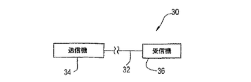
図3に示されるように、本明細書に開示された光ファイバ32が光ファイバ通信システム30で利用され得る。システム30は送信機34及び受信機36を含み、光ファイバ32は送信機34と受信機36との間の光信号の送信を可能にする。システム30は、好ましくは、2方向通信を可能にする。なお、送信機34及び受信機36は説明の目的で示されている。かかるシステム30は、好ましくは、本明細書に開示された光ファイバのセクションまたはスパンを有するリンクを含む。また、かかるシステム30は、本明細書に開示された光ファイバの1つ以上のセクション又はスパンに光学的に接続された1つ以上の光デバイス、例えば、1つ以上の再生機、増幅器、又は、分散補償モジュールを含み得る。少なくとも1つの好ましき実施例において、本発明による光ファイバ通信システムは間に再生機の存在なしに光ファイバによって接続された送信機及び受信機を含む。他の好ましき実施例において、本発明による光ファイバ通信システムは間に増幅器の存在なしに光ファイバによって接続される送信機及び受信機を含む。更に他の好ましき実施例において、本発明による光ファイバ通信システムは、間に増幅器、再生機、及び、中継器を有しない光ファイバによって接続された送信機及び受信機を含む。
As shown in FIG. 3, the
好ましくは、本明細書に開示された光ファイバは水の含有量が低く、好ましくは、低水ピーク光ファイバ、即ち、特定の波長領域(特に、1383nm窓)において、相対的に低い、又は、ゼロの水ピークを呈する減衰カーブを有する。 Preferably, the optical fiber disclosed herein has a low water content, preferably a low water peak optical fiber, i.e. relatively low in a specific wavelength region (especially a 1383 nm window), or It has an attenuation curve that exhibits a zero water peak.
低水ピーク光ファイバを製造する方法は、2001年11月27日に出願された米国特許出願第09/722,804号、2000年4月11日に出願された米国特許出願第09/547,598号、2000年12月22日に出願された米国特許仮出願第60/258,179号、及び、2001年2月28日に出願された米国特許仮出願第60/275,015号に開示され、これらの内容は引用によってここに組み入れられる。 Methods for making low water peak optical fibers are described in US patent application Ser. No. 09 / 722,804, filed Nov. 27, 2001, US Patent Application No. 09/547, filed Apr. 11, 2000, 598, U.S. Provisional Application No. 60 / 258,179 filed on Dec. 22, 2000, and U.S. Provisional Application No. 60 / 275,015 filed on Feb. 28, 2001. The contents of which are incorporated herein by reference.
図4に典型的に説明されるように、スートプリフォーム又はスート体21は、流動体混合物の少なくともいくつかの成分を化学的に反応させて形成される。流動体混合物は、好ましくは、シリカベースの反応生成物を形成する酸化物からなる、少なくとも1つのガラス形成プリカーサ化合物を含む。この反応生成物の少なくとも一部は、基体の方へ導かれて、少なくともこの一部が酸素と結びついた水素を典型的に含むポーラスシリカ体を形成する。かかるスート体は、例えば、OVD工程を経たベイトロッド上にスート層を堆積することによって形成される。かかるOVD工程は、図4に説明される。
As typically illustrated in FIG. 4, the soot preform or
図4に示されるように、基体もしくはベイトロッドもしくはマンドレル31が中空又は環状のハンドル33の如きガラス体を介して挿入されて旋盤(図示せず)に取り付けられる。かかる旋盤は、スート生成バーナー35の近くでマンドレル31を回転し並進するように設計されている。マンドレル31が回転、及び、並進するとき、一般にスートとして公知のシリカベース反応生成物37がマンドレル31の方向へ導かれる。シリカベース反応生成物37の少なくとも一部がマンドレル31上、及び、スート体21を形成するハンドル33の一部の上に堆積する。
As shown in FIG. 4, a base or bait rod or mandrel 31 is inserted through a glass body such as a hollow or
所望の量のスートがマンドレル31に堆積すると、スート堆積は終了して、マンドレル31がスート体21から取り除かれる。
When the desired amount of soot is deposited on the mandrel 31, soot deposition is terminated and the mandrel 31 is removed from the
マンドレル31の除去後の図5及び図6に図示されるように、スート体21が軸方向に通る中央線穴40を画定する。好ましくは、スート体21は、ダウンフィードデバイス42のハンドル33によって吊され、圧密化炉44内に配置される。ハンドル33から離れた方の中央線穴40の端部は、好ましくは、圧密化炉44内にスート体21が位置する前に、下部栓46と位置合わせされる。好ましくは、下部栓46が位置決めされて摩擦ばめによってスート体21の場所に保持される。栓46が更に好ましくはテーパー付けされて、スート体21内へ進入を容易にして、少なくとも一時的に添付し少なくとも緩いことを可能にする。
As shown in FIGS. 5 and 6 after removal of the mandrel 31, a
スート体21は、好ましくは、例えば、スート体21を圧密化炉44内で上昇した温度で塩素含有雰囲気にさらすことによって、化学的に乾燥される。塩素含有雰囲気48は、スート体21から製造される光導波路ファイバの特性における望まない効果を有する水及び他の不純物を効果的に取り除く。スート体21を形成するOVDにおいて、塩素がスートを通って十分に流れ、中央線穴40を囲む中央線領域を含む空間全体を効果的に乾燥する。
The
化学的乾燥ステップに続いて、炉の温度は、スート空間が焼結したガラスプリフォームに圧密化するのに十分な温度(好ましくは、1500℃)に上昇せしめられる。中央線穴40が、圧密化ステップの間、閉じられて、中央線穴は中央線穴が閉じる前に水素化合物によって再び濡らされる機会を有しない。好ましくは、中央線領域が1ppbよりも小の重量平均OH量を有する。
Following the chemical drying step, the furnace temperature is raised to a temperature sufficient to consolidate the soot space into the sintered glass preform (preferably 1500 ° C.). The
中央線穴を水素化合物を含む雰囲気にさらすことが、圧密化の間に中央線穴を閉じることによって、有意に取り除かれ又は妨げられ得る。 Exposing the central line hole to an atmosphere containing a hydride can be significantly removed or prevented by closing the central line hole during consolidation.
図6に説明される好ましき実施例において、下部栓46の如きガラス体が中央線穴40内のハンドル33から遠いスート体21の端部に位置する。また、図5に示されるように、開放端64を有する空洞管ガラス栓もしくは上部栓60の如きガラス体が、スート体21の中央線穴40内に栓46の反対側に位置する。上部栓60が管ハンドル33の中空内に配置される。塩素乾燥に続いて、スート体21が圧密化炉44の高温領域に導入され、焼結したガラスプリフォーム又は圧密化したガラスプリフォームの中に中央線穴40を封止し、且つスート体21を圧密化する。乾燥と圧密化が任意に同時に起こりうる。圧密化の間、スート体21はいくらか縮小し、下部栓46と上部栓60の下端部に係合し、それによって、生じた焼結したガラスプリフォームを栓46と栓60に溶解し、中央線穴40を封止する。中央線穴40の上部と下部の両方を封止することが、高温領域を通して1過程のスート体21で達成され得る。好ましくは、圧密化したガラスプリフォーム又は焼結したガラスプリフォームが上昇した温度で、好ましくは、保持するオーブン内で、保持され、中央線穴40から拡散する不活性ガスを封止された中央線穴40内で不活性真空にすることを可能にする。好ましくは、上部栓60は、不活性ガスの拡散がより適切に起こり得る相対的に薄い壁を有する。図6に図示されるように、上部栓60は、好ましくは、ハンドル33内で栓60を支持する拡大した部分62、及び、スート体21の中央線穴40内に伸長する細い部分64を有する。また、好ましくは、栓60は、好ましくはハンドル33の丈夫な部分を占め得る延伸中空部分66を含む。中空部分66が中央線穴40に更なる体積を有し、それによって、不活性ガスの拡散に続く中央線穴40内のよりよい真空を有する。
In the preferred embodiment illustrated in FIG. 6, a glass body, such as the lower plug 46, is located at the end of the
栓60の延伸部分66による体積が封止された中央線穴40に更なる体積を与える。その有利な点の詳細が、下記に記載される。
Additional volume is provided to the
本明細書に記載されるように、下部栓46及び上部栓60は、好ましくは、溶融石英栓の如く重量比で約31ppmよりも小の含水率、好ましくは、化学的に乾燥したシリカ栓の如く重量比で5ppbよりも小の含水率を有する。一般的に、かかる栓は塩素含有雰囲気において乾燥されるが、他の化学乾燥物質を含む雰囲気が等価的に適用できる。理想的には、ガラス栓が重量比で1ppbよりも小の含水率を有する。更に、ガラス栓は好ましくは約200μmから約2mmまでの厚さの範囲に亘る薄い壁栓である。更により好ましくは、栓60の少なくとも一部は約0.2から約0.5mmの壁の厚さを有する。より更に好ましくは、伸ばされた部分66が約0.3mmから約0.4mmの壁の厚さを有する。より薄い壁が拡散を促進するが、取扱いの際により破損し易い。
As described herein, the lower plug 46 and the
このように、中央線穴が封止されて中央線穴内に不活性真空が作られた後、不活性ガスが好ましくは中央線穴から拡散され、薄い壁のガラス栓が中央線穴から不活性ガスの早急な拡散を促進する。栓がより薄くなると、拡散の速度がより速くなる。圧密化ガラスプリフォームが好ましくはガラスプリフォームを十分伸ばす高い温度(好ましくは、約1950℃から約2100℃)に熱せられ、それによって、プリフォームの直径を減少し、コア茎又は光ファイバの如き円筒状のガラス体を形成する。続いて、中央線穴が圧壊し固体中央線領域を形成する。圧密化の間に不活性に封止された中央線穴内に維持された減少した圧力は、全体として、線引き(又は再線引き)処理の間、完全な中央線穴閉鎖を促進するのに、十分である。図7は、中央線軸28、オーバークラッド部分82に包囲される半径Rjを有する内部クラッド部分84によって包囲される半径Riを有するコア部分86を有する光ファイバ80の典型的な等角投影断面図を示す。
Thus, after the center line hole is sealed and an inert vacuum is created in the center line hole, the inert gas is preferably diffused from the center line hole, and the thin wall glass plug is inert from the center line hole. Promotes the rapid diffusion of gas. The thinner the plug, the faster the rate of diffusion. The consolidated glass preform is preferably heated to a high temperature (preferably about 1950 ° C. to about 2100 ° C.) that sufficiently stretches the glass preform, thereby reducing the diameter of the preform, such as a core stem or optical fiber. A cylindrical glass body is formed. Subsequently, the centerline hole collapses to form a solid centerline region. The reduced pressure maintained in the inertly sealed centerline hole during consolidation is generally sufficient to facilitate complete centerline hole closure during the drawing (or redrawing) process. It is. FIG. 7 shows a typical isometric cross section of an
従って、全体として、低OHオーバートーン光減衰が達成され得る。例えば、950nm又は1240nmの如き、他のOHが誘導する水ピークと同様に、1383nmでの水ピークが低くなり得て、ほぼ消滅する。 Thus, overall, low OH overtone light attenuation can be achieved. For example, similar to other OH-induced water peaks such as 950 nm or 1240 nm, the water peak at 1383 nm can be low and almost disappear.
低水ピークは、特に約1340nmから約1470nmの間の伝送信号に対して、全体として、より低い減衰損失を有する。さらに、低水ピークは1つ又は複数の励起波長で動作し得るラマン励起又はラマン増幅器の如き、光ファイバに光学的に結合した励起光送信デバイスの改良された励起性能を提供する。好ましくは、ラマン増幅器が所望の動作波長又は波長領域より約100nm低い1つ又は複数の波長で励起する。例えば、約1550nmの波長で動作信号を搬送する光ファイバが1450nm辺りの励起波長でラマン増幅器で励起され得る。このように、約1400nmから約1500nmまでの波長領域内でより低いファイバ減衰が励起減衰を減少し、励起性能(例えば、特に1400nm辺りの励起波長に対する励起出力の1mW当たりの利得)を向上する傾向がある。一般的に、ファイバにおけるOH不純物の増加に対して、水ピークが高さと同様に幅も大きくなる。それ故、より小さい水ピークによって、動作信号波長に対しても励起波長での増幅に対しても、より効果的な動作のより幅広い選択ができる。このように、OH不純物を低減することが、例えば、約1260nmから約1650nmの間の波長で損失を低減し得て、特に低減された損失が1383nm水ピーク領域で得られて、これによって、より有効なシステム動作を得る。 The low water peak has an overall lower attenuation loss, especially for transmission signals between about 1340 nm and about 1470 nm. In addition, the low water peak provides improved pumping performance of a pumping light transmission device optically coupled to an optical fiber, such as Raman pumping or a Raman amplifier that can operate at one or more pumping wavelengths. Preferably, the Raman amplifier is excited at one or more wavelengths that are about 100 nm below the desired operating wavelength or wavelength region. For example, an optical fiber carrying an operating signal at a wavelength of about 1550 nm can be pumped with a Raman amplifier at a pump wavelength around 1450 nm. Thus, lower fiber attenuation in the wavelength region from about 1400 nm to about 1500 nm reduces pump attenuation and tends to improve pump performance (eg, gain per mW of pump power, especially for pump wavelengths around 1400 nm). There is. Generally, as the OH impurity increases in the fiber, the water peak increases in width as well as in height. Therefore, the smaller water peak allows a wider selection of more effective operation, both for the operating signal wavelength and for amplification at the excitation wavelength. Thus, reducing OH impurities can reduce loss, for example, at wavelengths between about 1260 nm and about 1650 nm, and particularly reduced loss can be obtained in the 1383 nm water peak region, thereby making it more Get effective system operation.
本明細書に開示されたファイバがOVD処理によって製造されたとき、低PMD値を呈する。光ファイバ又はファイバ部分の低偏光モード分散(PMD)を達成するための方法と装置が2001年7月31日に出願された米国特許仮出願第60/309,160号、及び、2000年4月17日に出願されたPCT/US/10303に開示されている。プリフォームの中央線穴領域に関する更なる方法及び装置が、「光ファイバ及び低偏光モード分散及び低減衰光ファイバを製造する方法」として、2000年4月26日に出願された米国特許出願第09/558,770号、及び、「低水ピーク光導波路ファイバ及びその製造方法」として、1999年4月26日に出願された米国特許仮出願第60/131,033号に開示されている。これら全ては引用によってここに組み入れられる。光ファイバの巻き取りは、本明細書に開示されたファイバのより低いPMD値を与え得る。 The fibers disclosed herein exhibit low PMD values when manufactured by OVD processing. US Patent Provisional Application No. 60 / 309,160, filed July 31, 2001, and April 2000, for a method and apparatus for achieving low polarization mode dispersion (PMD) of an optical fiber or fiber portion. It is disclosed in PCT / US / 10303 filed on the 17th. A further method and apparatus relating to the central line hole region of a preform is described in US patent application Ser. No. 09, filed Apr. 26, 2000, as “Method of Manufacturing Optical Fiber and Low Polarization Mode Dispersion and Low Attenuation Optical Fiber” No./558,770 and “low water peak optical waveguide fiber and manufacturing method thereof” are disclosed in US Provisional Application No. 60 / 131,033 filed on Apr. 26, 1999. All of which are hereby incorporated by reference. Optical fiber winding may provide lower PMD values for the fibers disclosed herein.
図8を参照すると、本明細書に開示された光導波路ファイバは、好ましくは、中央線から中央領域外径(R1j)まで放射状に外側に延在する、最大相対屈折率パーセント(Δ1,MAX)を持つ正の相対屈折率パーセント(Δ1%(r))を有する中央領域4と、中央領域4を包囲しモート中間点(R2mid)に配置されるモート幅(W2)を有し且つ最小屈折率パーセント(Δ2,MIN)を持つ負の相対屈折率パーセント(Δ2%(r))を有する第1環状領域(もしくは、「モート」)6と、第1環状領域6を包囲しリング中間点(R3mid)に配置されるリング幅(W3)を有する最大相対屈折率パーセント(Δ3,MAX)を持つ正の相対屈折率パーセント(Δ3%(r))を有する第2環状領域(もしくはリング)8と、第2環状領域8を包囲し相対屈折率パーセント(Δc%(r))を有する外側環状クラッド領域14とを有する。好ましくは、Δ1,MAX>Δ3,MAX>Δ2,MINであり、Δ2%(r)が負である。
Referring to FIG. 8, the optical waveguide fiber disclosed herein preferably has a maximum relative refractive index percentage (Δ 1,1 ) extending radially outward from the center line to the central region outer diameter (R 1j ) . A
中央領域4が、ファイバの中央線(R1i=0)から中央領域外径(R1j)(Δ%(r)が0%に達する位置)まで延在する。R1hhが、Δ1,MAXの半値高さ、もしくは、半値ピーク高さの半径を示す。
The
モート6がモート内部半径(R2i)(Δ%(r)が負になる位置)からモート外径(R2j)(Δ%(r)が0%に達する位置)まで延在する。モート幅(W2)がR2iとR2jの間の放射方向の距離として定義される。モート中間点(R2mid)がR2iとR2jの中間である。
The
好ましくは、第1環状領域6が中央領域4に隣接し、即ち、好ましくは、R1j=R2iである。
Preferably, the first
リング8は、リング内径(R3i)(Δ%(r)が正になる位置)からリング外径(R3j)(Δ%(r)が0%に達する位置)まで延在する。リング幅(W3)は、R3iとR3jの間の放射方向の距離として定義される。リング8は、「ピーク」を持つ正の相対屈折率又は最大屈折率パーセント(Δ3,MAX)を有する。R3hhiは、Δ3,MAXの半値高さの最初の放射方向に内側の位置である。R3hhjは、Δ3,MAXの半値高さの最初の放射方向に外側の位置である。リング半値幅HHPW3は、内側半径(R3hhi)と外側半径(R3hhj)とによって境界とされる。リング半値幅(HHPW3)の中間点は、R3hhiとR3hhjの間の放射方向の距離の半分である半径(R3hhmid)である。好ましくは、Δ3,MAXはR3hhmidである。好ましくは、R3hhmidはリング8の中間点と一致する。
The
いくつかの好ましき実施例において、第2環状領域8は第1環状領域6に隣接する。即ち、R2j=R3iである。
In some preferred embodiments, the second
いくつかの好ましき実施例において、光導波路ファイバは、第2環状領域8を包囲し第2環状領域8と外側環状領域14との間に配置される第3環状領域(もしくはガター)10を含む。第3環状領域10は、最小屈折率パーセント(Δ4,MIN)を持つ負の相対屈折率パーセント(Δ4%(r))を有する。
In some preferred embodiments, the optical waveguide fiber includes a third annular region (or gutter) 10 that surrounds the second
ガター10が、ガター内側半径(R4i)(Δ%(r)が負になる位置)からガター外側半径(R4j)(Δ%(r)が0%に達する位置)まで延在する。ガター幅(W4)は、R4iとR4jの間の放射方向の距離として定義される。ガター幅(W4)は、R4iとR4jの間の放射方向の距離として定義される。ガターの中間点(R4mid)は、R4iとR4jの中間である。r>R4jに対して相対屈折率パーセント(Δ4%(r))は、好ましくは0%である。
The
いくつかの実施例において、第3環状領域10は第2環状領域8に隣接する。即ち、R3j=R4iである。
In some embodiments, the third
光ファイバ、又は、そのある部分の分布体積は、次のように定義される。 The distribution volume of the optical fiber or a part thereof is defined as follows.

ここで、r0及びrfは、分布体積が計算されるファイバの部分の半径のそれぞれ始点と終点である。 Here, r 0 and r f are the start point and end point of the radius of the portion of the fiber for which the distributed volume is calculated.
上記した定義の物理パラメータが、適切なところで残りの図面に適用される。 The physical parameters defined above apply to the remaining drawings where appropriate.
光導波路ファイバの製造の間、ドーパントの拡散が本明細書に開示された分布の角の丸めの原因となり得り、約0.5μmまでの領域を占め得る中央線屈折率低下部の原因となり得る。例えば、ドーピングステップにおけるかかる拡散のいくらかを補償することは可能であるが、多くの場合それは必要ではない。 During the manufacture of optical waveguide fibers, dopant diffusion can cause rounding of the distribution corners disclosed herein and can cause a centerline refractive index drop that can occupy a region up to about 0.5 μm. . For example, it is possible to compensate for some such diffusion in the doping step, but in many cases it is not necessary.
中央領域分布体積(もしくは「中央領域体積」)は、R1iからR1jまで計算される。モート分布体積(もしくは「モート体積」)は、R2iからR2jまで計算される。リング分布体積(もしくは「リング体積」)は、R3iからR3jまで計算される。ガター分布体積(もしくは「ガター体積」)は、R4iからR4jまで計算される。全分布体積は、R1iからファイバの最も外側の直径まで計算される。ファイバの最も外側の位置は、定義によって相対屈折率Δ%(r)=0を有し分布体積に全く寄与しない。本明細書に開示されたファイバの物理特性が記載される下記の表に、その全分布体積と同様に、中央コア領域、モート、リング、もしあればガターに対応する部分の計算された分布体積(単位%・μm2)が含まれる。分散スロープ(もしくは「スロープ」)は、ps/nm2/kmの単位で与えられる。
[実施例1乃至5]
The central region distribution volume (or “central region volume”) is calculated from R 1i to R 1j . The mote distribution volume (or “mote volume”) is calculated from R 2i to R 2j . The ring distribution volume (or “ring volume”) is calculated from R 3i to R 3j . The gutter distribution volume (or “gutter volume”) is calculated from R 4i to R 4j . The total distributed volume is calculated from R 1i to the outermost diameter of the fiber. The outermost position of the fiber has a relative refractive index Δ% (r) = 0 by definition and does not contribute to the distribution volume at all. The table below, which describes the physical properties of the fiber disclosed herein, as well as its total distribution volume, as well as the calculated distribution volume of the portion corresponding to the central core region, moat, ring, and gutter, if any. (Unit% · μm 2 ) is included. The dispersion slope (or “slope”) is given in units of ps / nm 2 / km.
[Examples 1 to 5]
表1に、本明細書に開示されたファイバの第1乃至第5の実施例(実施例1−5)の物理パラメータが記載される。実施例1乃至4の相対屈折率分布は、表1に見られる特定の分布の物理パラメータに対応した項目を有している図8に示される実施例3の分布で一般的に表される。実施例5は、表1の対応する項目に関連して図9に示される。表2に、実施例1乃至5の光学特性が記載される。 Table 1 lists the physical parameters of the first to fifth examples (Examples 1-5) of the fiber disclosed in this specification. The relative refractive index distributions of Examples 1 to 4 are generally represented by the distribution of Example 3 shown in FIG. 8 having items corresponding to the physical parameters of the specific distribution found in Table 1. Example 5 is shown in FIG. 9 in connection with the corresponding items in Table 1. Table 2 lists the optical characteristics of Examples 1-5.
表3に、本明細書に開示されたファイバの第6乃至第10の実施例(実施例6−10)の物理パラメータが記載される。実施例6乃至9の相対屈折率分布は、表3に見られる特定の分布の物理パラメータに対応する項目を有している図10に示される実施例8の分布で一般的に表される。実施例10は、表3の対応する項目に関連して図11に示される。表4に、実施例6乃至10の光学特性が記載される。 Table 3 lists the physical parameters of the sixth to tenth examples (Examples 6-10) of the fiber disclosed in this specification. The relative refractive index distributions of Examples 6 to 9 are generally represented by the distribution of Example 8 shown in FIG. 10 having items corresponding to the physical parameters of the specific distribution found in Table 3. Example 10 is shown in FIG. 11 in connection with corresponding items in Table 3. Table 4 lists the optical properties of Examples 6-10.
表5に、本明細書に開示されたファイバの第11乃至第15の実施例(実施例11−15)の物理パラメータに記載される。実施例11乃至14の相対屈折率分布は、表5に見られる特定の分布の物理パラメータに対応した項目を有している図12に示される実施例13の分布で一般的に表される。実施例15に、表5の対応する項目に関連して図13に示される。表6に、実施例11乃至15の光学特性が記載される。 Table 5 lists the physical parameters of the eleventh to fifteenth examples (Examples 11-15) of the fiber disclosed in this specification. The relative refractive index distributions of Examples 11 to 14 are generally represented by the distribution of Example 13 shown in FIG. 12 having items corresponding to the physical parameters of the specific distribution found in Table 5. Example 15 is shown in FIG. 13 in relation to the corresponding items in Table 5. Table 6 describes the optical characteristics of Examples 11 to 15.
表7に、本明細書に開示されたファイバの第16乃至第20の実施例(実施例16−20)の物理パラメータが記載される。実施例16乃至19の相対屈折率分布は、表7に見られる特定の分布の物理パラメータに対応した項目を有している図14に示される実施例18の分布で一般的に表される。実施例20は、表7の対応する項目に関連して図15に示される。表8に、実施例16乃至20の光学特性が記載される。 Table 7 lists the physical parameters of the sixteenth to twentieth examples (Examples 16-20) of the fiber disclosed in this specification. The relative refractive index distributions of Examples 16 to 19 are generally represented by the distribution of Example 18 shown in FIG. 14 having items corresponding to the physical parameters of the specific distribution found in Table 7. Example 20 is shown in FIG. 15 in connection with corresponding items in Table 7. Table 8 lists the optical properties of Examples 16-20.
表9に、本明細書に開示されたファイバの第21乃至第25の実施例(実施例21−25)の物理パラメータが記載される。実施例21乃至25の相対屈折率分布は、表9に見られる特定の分布の物理パラメータに対応した記載事項を有している図16に示される実施例24の分布で一般的に表される。表10に、実施例21乃至25の光学特性が記載される。 Table 9 lists the physical parameters of the twenty-first to twenty-fifth embodiments (Examples 21-25) of the fiber disclosed in this specification. The relative refractive index distributions of Examples 21 to 25 are generally represented by the distribution of Example 24 shown in FIG. 16 having entries corresponding to the physical parameters of the specific distribution found in Table 9. . Table 10 lists the optical properties of Examples 21-25.
表11に、本明細書に開示されたファイバの第26乃至第31の実施例(実施例26−31)の物理パラメータが記載される。実施例26乃至31の相対屈折率分布は、表11に見られる特定の分布の物理パラメータに対応した項目を有している図17に示される実施例30の分布で一般的に表される。表12に、実施例26乃至31の光学特性が記載される。 Table 11 lists the physical parameters of the twenty-sixth through thirty-first examples (Examples 26-31) of the fiber disclosed in this specification. The relative refractive index distributions of Examples 26 to 31 are generally represented by the distribution of Example 30 shown in FIG. 17 having items corresponding to the physical parameters of the specific distribution found in Table 11. Table 12 lists the optical properties of Examples 26-31.
表13に、本明細書に開示されたファイバの第32乃至第36の実施例(実施例32−36)の物理パラメータが記載される。実施例32又は33の相対屈折率分布は、表13の対応する項目に関連して、図18に示される実施例33の分布で一般的に表される。実施例34又は35の相対屈折率分布は、表13の対応する項目に関連して、図19に示される実施例35の分布で一般的に表される。実施例36の相対屈折率分布は、表13に見られる特定の分布の物理パラメータに対応した項目を有して、図20に示される分布によって表される。表14に、実施例32乃至36の光学特性が記載される。 Table 13 lists the physical parameters of the thirty-second to thirty-sixth examples (Examples 32-36) of the fiber disclosed herein. The relative refractive index distribution of Example 32 or 33 is generally represented by the distribution of Example 33 shown in FIG. 18 in relation to the corresponding items in Table 13. The relative refractive index distribution of Example 34 or 35 is generally represented by the distribution of Example 35 shown in FIG. 19 in relation to the corresponding items in Table 13. The relative refractive index distribution of Example 36 is represented by the distribution shown in FIG. 20 with items corresponding to the physical parameters of the specific distribution found in Table 13. Table 14 lists the optical characteristics of Examples 32-36.
表15に、本明細書に開示された光ファイバの第37の実施例(実施例37)の物理パラメータが記載される。実施例37の相対屈折率分布が表15に対応する項目に関連して、図21に示される分布によって表される。光ファイバプリフォームが、気相蒸着処理を経て図21に示される屈折率分布によって準備され、光ファイバプリフォームが光導波路ファイバに線引きされ、ファイバの測定された特性が表16に記載される。図22は、図21のファイバの様々な波長で測定された分散及び分散スロープを示す。
[実施例38]
Table 15 lists the physical parameters of the thirty-seventh example (Example 37) of the optical fiber disclosed in this specification. The relative refractive index distribution of Example 37 is represented by the distribution shown in FIG. 21 in relation to the items corresponding to Table 15. An optical fiber preform is prepared with a refractive index profile shown in FIG. 21 via a vapor deposition process, the optical fiber preform is drawn into an optical waveguide fiber, and the measured properties of the fiber are listed in Table 16. FIG. 22 shows the dispersion and dispersion slope measured at various wavelengths for the fiber of FIG.
[Example 38]
また、表15に、本明細書に開示された光ファイバの第38の実施例(実施例38)の物理パラメータが記載される。実施例38の相対屈折率分布が表15に対応する項目に関連して、図23に示される分布によって表される。 Table 15 lists the physical parameters of the thirty-eighth embodiment (Example 38) of the optical fiber disclosed in this specification. The relative refractive index distribution of Example 38 is represented by the distribution shown in FIG. 23 in relation to the items corresponding to Table 15.
光ファイバは、図23の屈折率分布によるOVD処理を経て組み立てられる。図23の光ファイバの測定された特性が表16に記載される。図24は、図23のファイバに対する様々な波長で測定された分散及び分散スロープを示す。図25は、様々な波長で測定された図23のファイバに対するファイバ損失もしくは減衰を示す。 The optical fiber is assembled through an OVD process using the refractive index profile of FIG. The measured properties of the optical fiber of FIG. 23 are listed in Table 16. FIG. 24 shows the dispersion and dispersion slope measured at various wavelengths for the fiber of FIG. FIG. 25 shows fiber loss or attenuation for the fiber of FIG. 23 measured at various wavelengths.
本明細書に開示された多くの実施例の光ファイバが、OVD、PCVD、IVD、VAD、又は、MCVD法、又は、当業者によって知られた他の適切な方法を経て、作られ得る。
[実施例39]
Many example optical fibers disclosed herein may be made via OVD, PCVD, IVD, VAD, or MCVD methods, or other suitable methods known by those skilled in the art.
[Example 39]
表15に、本明細書に開示された光ファイバの第39の実施例(実施例39)による物理パラメータが記載される。実施例39の相対屈折率は、表15の対応する項目に関連して、図26に示される。 Table 15 lists the physical parameters according to the thirty-ninth embodiment (Example 39) of the optical fiber disclosed herein. The relative refractive index of Example 39 is shown in FIG. 26 in relation to the corresponding item in Table 15.
好ましくは、LP01モード(しばしば、「基本モード」として参照される)に対するカットオフ波長が、十分高く、ベンドエッジの出現を妨げる。上記したように、測定されたケーブルカットオフ波長は、曲げ及び/又は機械的圧力による理論的なカットオフ波長値よりも小なのである。理論的カットオフは、それ故、ある曲げ端が、動作の最も高い所望の波長(例えば、Lバンドのどの位置であっても少なくとも1625nm)よりも上であることを確実にするほど十分高くなければならない。 Preferably, the cutoff wavelength for the LP01 mode (often referred to as the “fundamental mode”) is high enough to prevent the appearance of bend edges. As noted above, the measured cable cutoff wavelength is less than the theoretical cutoff wavelength value due to bending and / or mechanical pressure. The theoretical cutoff must therefore be high enough to ensure that some bend ends are above the highest desired wavelength of operation (eg, at least 1625 nm anywhere in the L band). I must.
図27は、全分布体積(即ち、中央コア領域、第1環状領域、第2環状、及び、(もしあれば)第3環状領域の合計)(単位%・μm2)に対する上記した本明細書に開示されたファイバの表された実施例の、LP01カットオフ波長(単位nm)を示す。 FIG. 27 shows the above specification for the total distribution volume (ie, the sum of the central core region, the first annular region, the second annular region, and the third annular region (if any)) (unit% · μm 2 ). FIG. 4 shows the LP01 cutoff wavelength (in nm) for the depicted embodiment of the fiber disclosed in FIG.
好ましくは、本明細書に開示された光ファイバのLP01カットオフ波長が、3500nmよりも大で、より好ましくは、約4000nmよりも大で、更により好ましくは約4500nmよりも大で、最も好ましくは約5000nmよりも大である。 Preferably, the LP01 cutoff wavelength of the optical fiber disclosed herein is greater than 3500 nm, more preferably greater than about 4000 nm, even more preferably greater than about 4500 nm, most preferably It is larger than about 5000 nm.
本明細書に開示された光ファイバの全分布体積が、好ましくは約−3%・μm2よりも大で、より好ましくは約−2%・μm2よりも大で、更により好ましくは約−1%・μm2よりも大で、最も好ましくは約0%・μm2よりも大である。 The total distributed volume of the optical fiber disclosed herein is preferably greater than about −3 %% μm 2 , more preferably greater than about −2% μm 2 , and even more preferably about − It is greater than 1% · μm 2 and most preferably greater than about 0% · μm 2 .
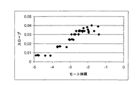
図28は、上で議論した表されたファイバの、モート体積(単位%・μm2)に対する1550nmでの分散スロープを示す。 FIG. 28 shows the dispersion slope at 1550 nm versus mote volume (unit% μm 2 ) for the represented fiber discussed above.
一般的に、モート体積のよりも大の大きさの絶対値、もしくは、絶対値が、1550nmの波長でより低い分散スロープをもたらす。好ましくは、モートの分布体積の絶対値が、約1%・μm2よりも大で、より好ましくは、約2%・μm2よりも大である。0.02から0.03ps/nm2/kmの間の1550nmでの分散スロープに対して、モート分布体積が、好ましくは、約−2%・μm2から約−3%・μm2の間にある。約0.02ps/nm2/kmよりも小の1550nmでの分散スロープに対して、モート分布体積が、好ましくは、約−3%・μm2よりも小である。約0.01ps/nm2/kmよりも小の1550nmでの分散スロープに対して、モート分布体積が、好ましくは、約−4%・μm2よりも小である。 In general, an absolute value greater than the moat volume, or an absolute value, results in a lower dispersion slope at a wavelength of 1550 nm. Preferably, the absolute value of the mote distribution volume is greater than about 1% · μm 2 , more preferably greater than about 2% · μm 2 . For a dispersion slope at 1550 nm of between 0.02 and 0.03 ps / nm 2 / km, the moat distribution volume is preferably between about −2% μm 2 and about −3% 3 μm 2 . is there. For a dispersion slope at 1550 nm of less than about 0.02 ps / nm 2 / km, the moat distribution volume is preferably less than about −3 %% μm 2 . For a dispersion slope at 1550 nm of less than about 0.01 ps / nm 2 / km, the moat distribution volume is preferably less than about −4% μm 2 .
図29は、上で開示したファイバの中央領域体積に対するモート体積を示す図である。 FIG. 29 is a diagram illustrating the mote volume relative to the central region volume of the fiber disclosed above.
好ましくは、中央領域体積は約2%・μm2よりも大であり、より好ましくは、約2%・μm2から3%・μm2の間にある。いくつかの好ましき実施例において、中央領域体積は、モート体積の絶対値に少なくともほぼ等しい。いくつかの好ましき実施例において、中央領域体積が約2.3%・μm2から2.6%・μm2の間にあって、モート体積が約−1.5%・μm2から3.5%・μm2の間にある。他の好ましき実施例において、約0.02ps/nm2/km未満の1550nmでの分散スロープを呈するので、モート体積の絶対値が約3%・μm2よりも大であり、中央領域体積が、好ましくは、約2.6%・μm2から約3.0%・μm2の間にあって、より好ましくは、約2.7%・μm2から約2.9%・μm2の間にある。 Preferably, the central region volume is greater than about 2% · μm 2 , more preferably between about 2% · μm 2 and 3% · μm 2 . In some preferred embodiments, the central region volume is at least approximately equal to the absolute value of the mote volume. In some PREFERRED EMBODIMENT Preferred embodiments, the central region volume be between about 2.3% · μm 2 of 2.6% · μm 2, moat volume of about -1.5% · μm 2 3.5 % · Μm 2 . In another preferred embodiment, it exhibits a dispersion slope at 1550 nm of less than about 0.02 ps / nm 2 / km, so the absolute value of the moat volume is greater than about 3% · μm 2 and the central region volume Is preferably between about 2.6% · μm 2 and about 3.0% · μm 2 , more preferably between about 2.7% · μm 2 and about 2.9% · μm 2 . is there.
図30は、上記した本明細書に開示されたファイバのリング体積に対するガター体積を示した図である。 FIG. 30 is a diagram showing the gutter volume with respect to the ring volume of the fiber disclosed in the present specification.
いくつかの好ましき実施例において、ファイバの相対屈折率分布はガターを有さず、リング体積が約4%・μm2よりも小であり、より好ましくは約3%・μm2よりも小である。 In some preferred embodiments, the relative refractive index profile of the fiber has no gutter, and the ring volume is less than about 4% μm 2 , more preferably less than about 3% μm 2. It is.
他の好ましき実施例において、リング体積は約4%・μm2よりも大であり、ガター体積の絶対値は約1%・μm2よりも大である。 In another preferred embodiment, the ring volume is greater than about 4% · μm 2 and the absolute value of the gutter volume is greater than about 1% · μm 2 .
好ましくは、ガター体積の絶対値はほぼリング体積以下である。 Preferably, the absolute value of the gutter volume is approximately equal to or less than the ring volume.
本明細書に開示された全ての光ファイバは、好ましくは、送信機と、受信機と、及び、光伝送線とを含む光信号伝送システムにおいて、使用され得る。該光伝送線は、送信機及び受信機に光学的に結合される。該光伝送線は、好ましくは、少なくとも1つの部分の光ファイバスパンを含み、好ましくはこれは少なくとも1つの光ファイバスパンのセクションである。 All the optical fibers disclosed herein can be preferably used in an optical signal transmission system including a transmitter, a receiver, and an optical transmission line. The optical transmission line is optically coupled to the transmitter and receiver. The optical transmission line preferably includes at least one portion of an optical fiber span, preferably this is a section of at least one optical fiber span.
更に、該システムは、好ましくは、光ファイバ部分に光学的に結合されたラマン増幅器の如き、少なくとも1つの増幅器を含む。 In addition, the system preferably includes at least one amplifier, such as a Raman amplifier optically coupled to the optical fiber portion.
更に、該システムは、好ましくは、光伝送線に光信号を伝搬できる複数のチャンネルを相互に連結する多重送信機を含み、少なくとも1つの光信号、より好ましくは少なくとも3つの光信号、最も好ましくは少なくとも10の光信号が約1260nmから約1625nmの間の波長で伝搬する。好ましくは、少なくとも1つの信号が1つ又は複数の波長領域(1310nm窓、1383nm窓、Sバンド、Cバンド、及び、Lバンド)を伝搬する。 In addition, the system preferably includes a multiplex transmitter that interconnects a plurality of channels capable of propagating an optical signal to an optical transmission line, and includes at least one optical signal, more preferably at least three optical signals, most preferably At least ten optical signals propagate at wavelengths between about 1260 nm and about 1625 nm. Preferably, at least one signal propagates in one or more wavelength regions (1310 nm window, 1383 nm window, S band, C band, and L band).
いくつかの好ましき実施例において、かかるシステムは、1310nm窓、1383nm窓、Sバンド、Cバンド、及び、Lバンドの波長領域のうちの少なくとも1つの波長領域、より好ましくは少なくとも2つの波長領域で、1つ又は複数の信号を伝送する低密度波長分割多重モードで動作し得る。 In some preferred embodiments, such a system includes at least one wavelength region of a 1310 nm window, a 1383 nm window, an S band, a C band, and an L band wavelength region, more preferably at least two wavelength regions. And can operate in a low density wavelength division multiplex mode transmitting one or more signals.
ある好ましき実施例において、かかるシステムは、20km以下の長さを有する本明細書に開示の光ファイバのセクションを含む。他の好ましき実施例において、かかるシステムが、20kmよりも長い長さを有する本明細書に開示された光ファイバのセクションを含む。更に他の好ましき実施例において、かかるシステムは、70kmよりも長い長さを有する本明細書に開示された光ファイバの一部を含む。 In one preferred embodiment, such a system includes a section of optical fiber as disclosed herein having a length of 20 km or less. In another preferred embodiment, such a system includes a section of optical fiber as disclosed herein having a length greater than 20 km. In yet another preferred embodiment, such a system includes a portion of the optical fiber disclosed herein having a length greater than 70 km.
ある好ましき実施例において、かかるシステムは、約1Gbit/s以下で動作する。他の好ましき実施例において、かかるシステムは、約2Gbit/s以下で動作する。更に他の好ましき実施例において、かかるシステムは、約10Gbit/s以下で動作する。より更に他の好ましき実施例において、かかるシステムは、約40Gbit/s以下で動作する。更に他の好ましき実施例において、かかるシステムは、約40Gbit/s以上で動作する。 In one preferred embodiment, such a system operates at about 1 Gbit / s or less. In other preferred embodiments, such a system operates at about 2 Gbit / s or less. In yet another preferred embodiment, such a system operates at about 10 Gbit / s or less. In yet another preferred embodiment, such a system operates at about 40 Gbit / s or less. In yet another preferred embodiment, such a system operates at about 40 Gbit / s or higher.
上の記載は、単に本発明の典型例にすぎず、特許請求の範囲によって定義される本発明の性質及び特徴を理解するための概要の提供を意図していることを、理解されるべきである。添付図面は本発明の更なる理解を提供するために含まれており、ここに取り入れられて本明細書の一部を構成する。図面は、本発明のいくつかの特徴及び実施例を示しており、本明細書の記載とともに本発明の原理及び動作の説明を与える。当業者にとって明らかな如く、本明細書に記載される発明のより好ましき実施例のさまざまな変更が特許請求の範囲によって定義される本発明の精神又は範囲内から逸脱することなくなされ得る。
It should be understood that the above description is merely exemplary of the invention, and is intended to provide an overview for understanding the nature and features of the invention as defined by the claims. is there. The accompanying drawings are included to provide a further understanding of the invention, and are incorporated in and constitute a part of this specification. The drawings illustrate some features and embodiments of the invention and together with the description serve to explain the principles and operation of the invention. It will be apparent to those skilled in the art that various modifications can be made to the preferred embodiments of the invention described herein without departing from the spirit or scope of the invention as defined by the claims.
Claims (34)
前記中央領域に隣接し且つこれを包囲し、負の相対屈折率パーセント(Δ2,MIN)を持つ最小相対屈折率パーセント(Δ2%(r))を有する第1環状領域と、
前記第1環状領域に隣接し且つこれを包囲し、最大相対屈折率パーセント(Δ3,MAX)を持つ正の相対屈折率パーセント(Δ3%(r))を有する第2環状領域と、
前記第2環状領域に隣接し且つこれを包囲し、相対屈折率パーセント(Δc%(r))を有する外側環状クラッド領域と、
を更に含むことを特徴とする請求項1記載の光導波路ファイバ。 A central region having a positive relative refractive index percentage (Δ 1 % (r)) extending radially outward from the central line and having a maximum relative refractive index percentage (Δ 1, MAX );
A first annular region adjacent to and surrounding the central region and having a minimum relative refractive index percent (Δ 2 % (r)) having a negative relative refractive index percent (Δ 2, MIN );
A second annular region having a positive relative refractive index percentage (Δ 3 % (r)) adjacent to and surrounding the first annular region and having a maximum relative refractive index percent (Δ 3, MAX );
An outer annular cladding region adjacent to and surrounding the second annular region and having a relative refractive index percentage (Δ c % (r));
The optical waveguide fiber according to claim 1, further comprising:
前記中央領域に隣接し且つこれを包囲し、最小相対屈折率パーセント(Δ2,MIN)を持つ負の相対屈折率パーセント(Δ2%(r))を有する第1環状領域と、
前記第1環状領域に隣接し且つこれを包囲し、最大相対屈折率(Δ3,MAX)を有する正の相対屈折率パーセント(Δ3%(r))を有する第2環状領域と、
前記第2環状領域を包囲し、相対屈折率パーセント(Δc%(r))を有する外側環状クラッド領域と、を含む光導波路ファイバであって、
前記第1環状領域が約−1.5%・μm2よりも小の分布体積を有し、前記全分布体積が−2%・μm2よりも大であることを特徴とする光導波路ファイバ。 A central region having a positive relative refractive index percentage (Δ 1 % (r)) with a maximum relative refractive index (Δ 1, MAX ) extending radially outward from said central line;
A first annular region having a negative relative refractive index percentage (Δ 2 % (r)) adjacent to and surrounding the central region and having a minimum relative refractive index percentage (Δ 2, MIN );
A second annular region having a positive relative refractive index percentage (Δ 3 % (r)) adjacent to and surrounding the first annular region and having a maximum relative refractive index (Δ 3, MAX );
An outer annular cladding region surrounding the second annular region and having a relative refractive index percentage (Δ c % (r)), comprising:
The first annular region has a small distribution volume than about -1.5% · μm 2, optical waveguide fiber wherein the total distribution volume is larger than -2% · μm 2.
Applications Claiming Priority (2)
| Application Number | Priority Date | Filing Date | Title |
|---|---|---|---|
| US35753902P | 2002-02-15 | 2002-02-15 | |
| PCT/US2003/003843 WO2003071325A1 (en) | 2002-02-15 | 2003-02-07 | Low slope dispersion shifted optical fiber |
Publications (2)
| Publication Number | Publication Date |
|---|---|
| JP2005517989A true JP2005517989A (en) | 2005-06-16 |
| JP2005517989A5 JP2005517989A5 (en) | 2005-12-22 |
Family
ID=27757631
Family Applications (1)
| Application Number | Title | Priority Date | Filing Date |
|---|---|---|---|
| JP2003570164A Pending JP2005517989A (en) | 2002-02-15 | 2003-02-07 | Low slope dispersion shifted optical fiber |
Country Status (6)
| Country | Link |
|---|---|
| US (1) | US7050687B2 (en) |
| EP (1) | EP1474712A1 (en) |
| JP (1) | JP2005517989A (en) |
| KR (1) | KR20040075982A (en) |
| AU (1) | AU2003210934A1 (en) |
| WO (1) | WO2003071325A1 (en) |
Families Citing this family (16)
| Publication number | Priority date | Publication date | Assignee | Title |
|---|---|---|---|---|
| KR100636332B1 (en) * | 1998-09-21 | 2006-10-19 | 피렐리 카비 에 시스테미 소시에떼 퍼 아찌오니 | Optical fiber for extended wavelength band |
| GB0101338D0 (en) * | 2001-01-18 | 2001-03-07 | Nds Ltd | Set-top-box with qam demodulator sharing between dtv/pvr and cable modem applications |
| US6633712B2 (en) * | 2001-03-16 | 2003-10-14 | Sowilo Networks, Inc. | Method and system for dispersion maps and enhanced distributed gain effect in long haul telecommunications |
| US7307782B2 (en) * | 2001-07-31 | 2007-12-11 | Sumitomo Electric Industries, Ltd. | Raman amplifier and optical communication system including the same |
| CN1310047C (en) * | 2002-12-18 | 2007-04-11 | 古河电气工业株式会社 | Optical fiber and light transfer circuit using same |
| US6904217B2 (en) * | 2003-01-29 | 2005-06-07 | Furukawa Electric North America | Method for the manufacture of optical fibers, improved optical fibers, and improved Raman fiber amplifier communication systems |
| KR101118404B1 (en) * | 2003-08-04 | 2012-03-06 | 스미토모 덴키 고교 가부시키가이샤 | Fiber optics |
| US7359602B2 (en) * | 2003-08-04 | 2008-04-15 | Sumitomo Electric Industries, Ltd. | Optical transmission line constituting method, optical transmission line and optical fiber |
| US7164833B2 (en) | 2003-09-24 | 2007-01-16 | Fitel U.S.A. Corp. | Optical fiber for improved performance in S-, C- and L-bands |
| FR2867865B1 (en) * | 2004-03-16 | 2008-05-30 | Cit Alcatel | CHROMATIC BAND DISPERSION COMPENSATION OPTICAL FIBER USING HIGHER ORDER MODE |
| KR100713429B1 (en) * | 2005-12-27 | 2007-05-04 | 삼성전자주식회사 | Manufacturing method of optical fiber |
| US8385702B2 (en) * | 2009-05-28 | 2013-02-26 | Corning Incorporated | Bend resistant multimode optical fiber |
| US8805141B2 (en) * | 2011-10-07 | 2014-08-12 | Corning Incorporated | Optical fiber illumination systems and methods |
| JP6134588B2 (en) * | 2012-07-24 | 2017-05-24 | 株式会社フジクラ | Optical fiber and optical transmission line |
| WO2018022413A1 (en) * | 2016-07-29 | 2018-02-01 | Corning Incorporated | Single mode optical fiber with chlorine doped core and low bend loss |
| CN109791250B (en) | 2016-09-21 | 2021-03-12 | 康宁股份有限公司 | Optical fiber with cladding having varying refractive index and method of forming the same |
Family Cites Families (42)
| Publication number | Priority date | Publication date | Assignee | Title |
|---|---|---|---|---|
| US4852968A (en) | 1986-08-08 | 1989-08-01 | American Telephone And Telegraph Company, At&T Bell Laboratories | Optical fiber comprising a refractive index trench |
| US4770492A (en) | 1986-10-28 | 1988-09-13 | Spectran Corporation | Pressure or strain sensitive optical fiber |
| US5553185A (en) | 1994-12-27 | 1996-09-03 | Corning Incorporated | Controlled dispersion optical waveguide |
| US5684909A (en) | 1996-02-23 | 1997-11-04 | Corning Inc | Large effective area single mode optical waveguide |
| CA2202586C (en) * | 1996-04-15 | 2003-05-06 | Masashi Onishi | Dispersion compensating fiber and optical transmission system including the same |
| US5878182A (en) | 1997-06-05 | 1999-03-02 | Lucent Technologies Inc. | Optical fiber having a low-dispersion slope in the erbium amplifier region |
| JP3830636B2 (en) | 1997-10-14 | 2006-10-04 | 株式会社フジクラ | Dispersion-shifted optical fiber |
| EP0959374B1 (en) * | 1997-12-05 | 2010-03-10 | Sumitomo Electric Industries, Ltd. | Dispersion flat optical fiber |
| US5905838A (en) | 1998-02-18 | 1999-05-18 | Lucent Technologies Inc. | Dual window WDM optical fiber communication |
| EP1066540A4 (en) * | 1998-02-23 | 2005-05-18 | Corning Inc | Low slope dispersion managed waveguide |
| US6321016B1 (en) | 1998-06-19 | 2001-11-20 | Pirelli Cavi E Sistemi S.P.A. | Optical fiber having low non-linearity for WDM transmission |
| DE19839870A1 (en) | 1998-09-02 | 2000-03-09 | Deutsche Telekom Ag | Single-mode optical fiber |
| CA2352268A1 (en) | 1998-11-26 | 2000-06-02 | Sumitomo Electric Industries, Ltd. | Optical fiber and optical transmission system including the same |
| EP1141754B1 (en) | 1998-12-18 | 2008-09-03 | Prysmian Cavi e Sistemi Energia S.r.l. | Optical fiber for metropolitan and access network systems |
| TW451088B (en) | 1999-04-16 | 2001-08-21 | Sumitomo Electric Industries | Optical fiber and optical transmission line including the same |
| US6785453B1 (en) | 1999-07-12 | 2004-08-31 | Fujikura Ltd. | Dispersion shifted optical fiber |
| CN1237356C (en) * | 1999-07-27 | 2006-01-18 | 康宁股份有限公司 | Optical waveguide having negative dispersion and large |
| WO2001007943A1 (en) | 1999-07-27 | 2001-02-01 | Fujikura Ltd. | Dispersion shift optical fiber |
| EP1124145A1 (en) | 1999-08-20 | 2001-08-16 | The Furukawa Electric Co., Ltd. | Optical fiber and optical transmission line including the same |
| JP4134468B2 (en) | 1999-12-13 | 2008-08-20 | 住友電気工業株式会社 | Optical fiber |
| FR2805620B1 (en) | 2000-02-24 | 2002-05-31 | Cit Alcatel | SINGLE-MODE CABLE OPTICAL FIBER FOR WAVELENGTH MULTIPLEXED OPTICAL FIBER TRANSMISSION NETWORK |
| US6633714B2 (en) | 2000-02-24 | 2003-10-14 | Alcatel | Optical fiber for wavelength division multiplex transmission systems |
| JP2001237777A (en) | 2000-02-25 | 2001-08-31 | Kddi Corp | Light transmission path |
| CN1178080C (en) | 2000-02-25 | 2004-12-01 | 古河电气工业株式会社 | Low-dispersion optical fiber and optical transmission system using low-dispersion optical fiber |
| WO2002014919A2 (en) | 2000-08-16 | 2002-02-21 | Corning Incorporated | Optical fiber with large effective area, low dispersion and low dispersion slope |
| KR100349320B1 (en) | 2000-08-25 | 2002-08-21 | 엘지전선 주식회사 | Optical fiber for optical transmission systems of wavelength division multiplexing method using densely spaced optical channels |
| DE60143664D1 (en) | 2000-08-31 | 2011-01-27 | Prysmian Spa | OPTICAL TRANSMISSION CONNECTION TO A FIBER WITH LOW DISPERSION AND RAMAN REINFORCEMENT |
| WO2002031553A2 (en) * | 2000-10-11 | 2002-04-18 | Corning Incorporated | Single mode optical waveguide fiber with reduced dispersion |
| FR2815418B1 (en) * | 2000-10-16 | 2003-05-16 | Cit Alcatel | FIBER FOR THE CHROMATIC DISPERSION COMPENSATION OF A NZ-DSF FIBER WITH POSITIVE CHROMATIC DISPERSION |
| JP2002162529A (en) * | 2000-11-28 | 2002-06-07 | Furukawa Electric Co Ltd:The | Optical fiber, and optical communication system using the optical fiber |
| JP2002258090A (en) | 2001-02-27 | 2002-09-11 | Furukawa Electric Co Ltd:The | Optical fiber with low loss |
| JP4443788B2 (en) | 2001-03-30 | 2010-03-31 | 古河電気工業株式会社 | Optical fiber and optical communication system using the optical fiber |
| JP2002365462A (en) | 2001-06-12 | 2002-12-18 | Furukawa Electric Co Ltd:The | Optical communication link |
| CA2389498A1 (en) | 2001-06-13 | 2002-12-13 | Fumio Takahashi | Method of winding optical fiber on reel |
| JP2003021743A (en) | 2001-07-09 | 2003-01-24 | Furukawa Electric Co Ltd:The | Optical fiber and optical transmission system using the same |
| JP2003114350A (en) | 2001-07-31 | 2003-04-18 | Furukawa Electric Co Ltd:The | Optical fiber, optical fiber component, and optical transmission method |
| FR2828939B1 (en) | 2001-08-27 | 2004-01-16 | Cit Alcatel | OPTICAL FIBER FOR A WAVELENGTH MULTIPLEXED TRANSMISSION SYSTEM |
| JP2003084163A (en) | 2001-09-07 | 2003-03-19 | Sumitomo Electric Ind Ltd | Optical fiber, optical transmission line, and optical communication system |
| JP3886771B2 (en) | 2001-10-29 | 2007-02-28 | 株式会社フジクラ | Single mode optical fiber and composite optical line for WDM |
| JP2003156649A (en) | 2001-11-19 | 2003-05-30 | Furukawa Electric Co Ltd:The | Optical fiber |
| US6633715B2 (en) * | 2001-12-06 | 2003-10-14 | Fitel Usa Corp. | Optical fiber having negative dispersion, negative dispersion slope and large effective area |
| JP2003287642A (en) | 2002-01-22 | 2003-10-10 | Fujikura Ltd | Optical fiber and optical transmission line |
-
2003
- 2003-02-07 KR KR10-2004-7012587A patent/KR20040075982A/en not_active Application Discontinuation
- 2003-02-07 WO PCT/US2003/003843 patent/WO2003071325A1/en not_active Application Discontinuation
- 2003-02-07 AU AU2003210934A patent/AU2003210934A1/en not_active Abandoned
- 2003-02-07 EP EP03742716A patent/EP1474712A1/en not_active Withdrawn
- 2003-02-07 JP JP2003570164A patent/JP2005517989A/en active Pending
- 2003-02-12 US US10/365,731 patent/US7050687B2/en not_active Expired - Fee Related
Also Published As
| Publication number | Publication date |
|---|---|
| AU2003210934A1 (en) | 2003-09-09 |
| WO2003071325A1 (en) | 2003-08-28 |
| US7050687B2 (en) | 2006-05-23 |
| US20030174988A1 (en) | 2003-09-18 |
| EP1474712A1 (en) | 2004-11-10 |
| KR20040075982A (en) | 2004-08-30 |
Similar Documents
| Publication | Publication Date | Title |
|---|---|---|
| JP5268358B2 (en) | Low-loss effective cross-section enlarged optical fiber | |
| EP1725898B1 (en) | Non-zero dispersion shifted optical fiber | |
| US7336877B2 (en) | Broadband optical fiber | |
| US7181118B2 (en) | Non-zero dispersion shifted optical fiber having large effective area, low slope and low zero dispersion | |
| US6943935B2 (en) | Dispersion-managed cable for raman-assisted transmission | |
| JP2009517702A (en) | Low attenuation / non-zero dispersion shifted optical fiber | |
| US7103251B2 (en) | Dispersion flattened NZDSF fiber | |
| JP2005517989A (en) | Low slope dispersion shifted optical fiber | |
| US6856743B2 (en) | NZDSF optical fiber with low dispersion zero and low slope | |
| US20040022509A1 (en) | Non-zero dispersion shifted optical fiber with depressed core having large effective area, low slope and low dispersion | |
| WO2008130334A2 (en) | Low cutoff large effective area optical fiber |
Legal Events
| Date | Code | Title | Description |
|---|---|---|---|
| A621 | Written request for application examination |
Free format text: JAPANESE INTERMEDIATE CODE: A621 Effective date: 20051110 |
|
| A131 | Notification of reasons for refusal |
Free format text: JAPANESE INTERMEDIATE CODE: A131 Effective date: 20080722 |
|
| A02 | Decision of refusal |
Free format text: JAPANESE INTERMEDIATE CODE: A02 Effective date: 20081216 |