RU2160503C2 - Radio communication line - Google Patents
Radio communication line Download PDFInfo
- Publication number
- RU2160503C2 RU2160503C2 RU99100583A RU99100583A RU2160503C2 RU 2160503 C2 RU2160503 C2 RU 2160503C2 RU 99100583 A RU99100583 A RU 99100583A RU 99100583 A RU99100583 A RU 99100583A RU 2160503 C2 RU2160503 C2 RU 2160503C2
- Authority
- RU
- Russia
- Prior art keywords
- input
- output
- inputs
- phase
- outputs
- Prior art date
Links
- GVVPGTZRZFNKDS-JXMROGBWSA-N geranyl diphosphate Chemical compound CC(C)=CCC\C(C)=C\CO[P@](O)(=O)OP(O)(O)=O GVVPGTZRZFNKDS-JXMROGBWSA-N 0.000 claims 1
- 230000005540 biological transmission Effects 0.000 abstract description 5
- 238000001514 detection method Methods 0.000 abstract 1
- 230000000694 effects Effects 0.000 abstract 1
- 239000000126 substance Substances 0.000 abstract 1
- 230000010355 oscillation Effects 0.000 description 13
- 230000009268 pathologic speech processing Effects 0.000 description 5
- 208000032207 progressive 1 supranuclear palsy Diseases 0.000 description 5
- 229920006261 self reinforced polyphenylene Polymers 0.000 description 5
- 102100027867 FH2 domain-containing protein 1 Human genes 0.000 description 4
- 101001060553 Homo sapiens FH2 domain-containing protein 1 Proteins 0.000 description 4
- 101001012154 Homo sapiens Inverted formin-2 Proteins 0.000 description 4
- 102100030075 Inverted formin-2 Human genes 0.000 description 4
- 230000008878 coupling Effects 0.000 description 4
- 238000010168 coupling process Methods 0.000 description 4
- 238000005859 coupling reaction Methods 0.000 description 4
- 101100068394 Arabidopsis thaliana GER3 gene Proteins 0.000 description 3
- 101100393014 Arabidopsis thaliana GLP1 gene Proteins 0.000 description 3
- 230000036039 immunity Effects 0.000 description 3
- 230000010287 polarization Effects 0.000 description 3
- 230000001360 synchronised effect Effects 0.000 description 3
- 230000015572 biosynthetic process Effects 0.000 description 2
- 238000010586 diagram Methods 0.000 description 2
- 230000002452 interceptive effect Effects 0.000 description 2
- 230000010363 phase shift Effects 0.000 description 2
- 238000000926 separation method Methods 0.000 description 2
- 230000001629 suppression Effects 0.000 description 2
- 101100100081 Oryza sativa subsp. japonica TPP3 gene Proteins 0.000 description 1
- 238000005314 correlation function Methods 0.000 description 1
- 230000008520 organization Effects 0.000 description 1
- 230000011514 reflex Effects 0.000 description 1
- 238000001228 spectrum Methods 0.000 description 1
Images
Landscapes
- Transceivers (AREA)
Abstract
Description
Предлагаемое устройство относится к области радиосвязи и может быть использовано в космических и наземных системах связи, использующих пространственную модуляцию. The proposed device relates to the field of radio communications and can be used in space and ground-based communication systems using spatial modulation.
Известны устройства для радиосвязи с повторным использованием частоты (см. пат. США N 4087818), в котором повторное использование частоты в условиях изменения параметров среды распространения сигналов и изменение взаимного расположения антенн достигается за счет обеспечения ортогональности по поляризации двух одновременно передаваемых сигналов с круговой или линейной поляризацией. Однако эти устройства из-за высоких требований к точности обеспечения ортогональности по поляризации передаваемых сигналов имеют сложную систему автоподстройки, использующую специальные пилот-сигналы. Кроме того, применение пилот-сигналов требует выделение дополнительных частотных каналов, на совпадающих со спектром передаваемых сигналов, что существенно усложняет конструкцию устройства и ухудшает его помехоустойчивость. Known devices for radio communication with frequency reuse (see US Pat. No. 4087818), in which frequency reuse under conditions of changing parameters of the signal propagation medium and changing the relative position of the antennas is achieved by ensuring polarization orthogonality of two simultaneously transmitted signals with circular or linear polarized. However, because of the high accuracy requirements for ensuring orthogonality in the polarization of the transmitted signals, these devices have a complex auto-tuning system using special pilot signals. In addition, the use of pilot signals requires the allocation of additional frequency channels that coincide with the spectrum of transmitted signals, which significantly complicates the design of the device and impairs its noise immunity.
Известно также устройство по а.с. N 1141978, содержащее два канала, в одном из которых информация передается с использованием угловой модуляции, а во втором канале - с использованием дополнительной модуляции сигналов по поляризации волн, позволяющей передавать дополнительную информацию (повторно использовать частоту). A device is also known for A.S. N 1141978, containing two channels, in one of which information is transmitted using angular modulation, and in the second channel - using additional modulation of signals by wave polarization, which allows transmitting additional information (reuse frequency).
Однако в случае использования широкополосных сигналов, что характерно для современных систем связи, низка помехоустойчивость приема информации по второму каналу, обусловленная низкой помехоустойчивостью опорного сигнала для синхронного детектора. However, in the case of using broadband signals, which is typical for modern communication systems, the noise immunity of receiving information on the second channel is low, due to the low noise immunity of the reference signal for a synchronous detector.
Наиболее близким по технической сущности к заявляемому объекту является "Аппаратура для передачи дискретной информации", авт.св. N 300946, принято за прототип. The closest in technical essence to the claimed object is "Equipment for the transmission of discrete information", ed. N 300946, taken as a prototype.
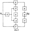
Функциональная схема устройства-прототипа приведена на фиг. 1, 2, где введены обозначения:
Передающее устройство:
1 - генератор колебаний несущей и тактовой частоты (ГТНЧ);
2 - формирователь ортогональной псевдослучайной последовательности (ФОПП);
3 - генератор псевдослучайной последовательности (ГПП);
4 - устройство фазирования;
5, 6 - первый и второй умножители соответственно;
7 - фазовращатель на 90o;
8 - фазовый манипулятор;
9 - схема сложения.The functional diagram of the prototype device is shown in FIG. 1, 2, where the notation is introduced:
Transmitter:
1 - oscillator carrier and clock frequency (GTNCH);
2 - shaper orthogonal pseudo-random sequence (FOPP);
3 - pseudo-random sequence generator (GLP);
4 - phasing device;
5, 6 - the first and second multipliers, respectively;
7 - phase shifter 90 o ;
8 - phase manipulator;
9 is a diagram of addition.
Приемное устройство:
10, 11 - первый и второй умножители соответственно;
12 - формирователь ортогональной псевдослучайной последовательности (ФОПП);
13 - генератор опорной псевдослучайной последовательности (ГОПП);
14 - устройство фазирования;
15 - устройство синхронизации;
16, 17 - первый и второй полосовые фильтры соответственно;
18 - фазовый детектор.Receiving device:
10, 11 - the first and second multipliers, respectively;
12 - shaper orthogonal pseudo-random sequence (FOPP);
13 - generator reference pseudorandom sequence (GOPP);
14 - phasing device;
15 - synchronization device;
16, 17 - the first and second band-pass filters, respectively;
18 is a phase detector.
Устройство-прототип содержит на передающей стороне ГНТЧ1, первый выход которого соединен с первыми входами ФОПП2 и ГПП3, вторые входы которых присоединены соответственно к первому и второму выходам устройства фазирования 4, выход ФОПП2 соединен с первым входом первого умножителя 5, второй вход которого соединен с выходом фазовращателя на 90o 7, а вход этого фазовращателя соединен с одним из входов фазового манипулятора 8 и вторым выходом ГНТЧ1, выход ГПП3 соединен с одним из входов второго умножителя 6, второй вход которого присоединен к выходу фазового манипулятора 8, а выход второго умножителя 6 соединен со вторым входом схемы сложения 9, первый вход которого соединен с выходом первого умножителя 5, выход сумматора 9 является выходом передатчика, первый вход фазового манипулятора 8 является информационным входом; на приемной стороне вход устройства синхронизации 15 соединен с первыми входами первого 10 и второго 11 умножителей, выходы которых соединены соответственно со входами первого 16 и второго 17 полосовых фильтров, выходы которых соединены соответственно с первым и вторым входами фазового детектора 18. выход которого является выходом устройства, выход устройства синхронизации 15 соединен с первыми входами ФОПП12 и ГОПП13, вторые входы которых присоединены соответственно к первому и второму выходам устройства фазирования 14, выход ФОПП12 соединен со вторым входом первого умножителя 10, а выход ГОПП13 соединен со вторым входом второго умножителя 11.The prototype device contains on the transmitting side GNTC1, the first output of which is connected to the first inputs of FOPP2 and GPP3, the second inputs of which are connected respectively to the first and second outputs of the
Устройство-прототип работает следующим образом. The prototype device operates as follows.
В передатчике ГНТЧ1 формирует две частоты: тактовую частоту для ФОПП2 и ГПП3 и несущую частоту сигнала. Тактовая частота с выхода ГНТЧ1 поступает на вход ФОПП2 и ГПП3, которые вырабатывают двойные псевдослучайные последовательности. Эти последовательности представляют собой совокупности биполярных импульсов постоянного тока одинаковой величины и длительности, которая определяется величиной тактовой частоты. Законы образования псевдослучайных последовательностей выбираются такими, чтобы обеспечить малую взаимную корреляцию между псевдослучайными последовательностями ФОПП2 и ТПП3 при любом фазовом сдвиге между ними (квазиортогональные двоичные псевдослучайные последовательности. Это условие необходимо для их эффективного разделения и подавления эхо-сигнала в приемнике. In the transmitter, GNTC1 generates two frequencies: the clock frequency for FOPP2 and GPP3 and the carrier frequency of the signal. The clock frequency from the output of GNTC1 is fed to the input of FOPP2 and GPP3, which generate double pseudorandom sequences. These sequences are collections of bipolar DC pulses of the same magnitude and duration, which is determined by the magnitude of the clock frequency. The laws of the formation of pseudo-random sequences are chosen so as to provide a small cross-correlation between the pseudo-random sequences of FOPP2 and TPP3 for any phase shift between them (quasi-orthogonal binary pseudo-random sequences. This condition is necessary for their effective separation and suppression of the echo signal in the receiver.
Устройство фазирования 4 устанавливают сдвиговые регистры ФОПП2 и ГПП3 в одинаковое начальное состояние, что обеспечивает связь по фазе их псевдослучайных последовательностей. Устройство фазирования 4 состоит из дешифраторов начальных состояний ФОПП2 и ГПП3 и импульсной схемы фазирования, которая обеспечивает совмещение их начальных состояний по фазе. Двоичная псевдослучайная последовательность с выхода ФОПП2 поступает на умножитель 5. На второй вход умножителя 5 через фазовращатель на 90o 7 с выхода ГНТЧ1 поступает колебание несущей частоты, которое в умножителе 5 умножается на двоичную псевдослучайную последовательность. В результате на выходе умножителя 5 образуется сигнал, представляющий собой колебание несущей частоты с постоянной амплитудой, манипулированное по фазе на 180o по закону двоичной псевдослучайной последовательности. Двоичная псевдослучайная последовательность с выхода ГПП3 поступает на умножитель 6, на второй вход которого через фазовый манипулятор с выхода ГНТЧ1 поступает колебание несущей частоты. На выходе умножителя 6 образуется сигнал, представляющий собой колебание несущей частоты с постоянной амплитудой, манипулированное по фазе на 180o по закону двоичной псевдослучайной последовательности. В зависимости от закона передаваемой информации фазовый манипулятор 8 осуществляет поворот фазы несущей частоты сигнала на выходе умножителя 6 относительно несущей частоты сигнала на выходе умножителя 5 на 0 или 180o. Таким образом, в зависимости от знака передаваемой информации несущие частоты этих сигналов сдвинуты между собой по фазе. С выходов умножителей 5 и 6 сигналы поступают на схему сложения 9, которая образует выходной сигнал передатчика, представляющий собой колебание несущей частоты с постоянной амплитудой, манипулированное по фазе на 0o, 90o, 180o и 270oC, причем моменты манипуляции и порядок следования этих величин фаз определяется соотношением знаков элементов двоичных псевдослучайных последовательностей ФОПП2 и ГПП3 и передаваемой разностью фаз. Со схемы сложения 9 сигнал поступает в высокочастотный передатчик и излучается в эфир.The
Принимаемый сигнал с выхода высокочастотного приемника поступает на умножители 10 и 11, аналогичные умножителям 5 и 6 передатчика. В умножителе 10 принимаемый сигнал умножается на двоичную псевдослучайную последовательность, которую вырабатывает ФОПП12, аналогичный ФОПП2 передатчика. Сигнал с выхода умножителя 10 поступает на полосовой фильтр 16, который выделяет колебание несущей частоты сигнала. В умножителе 11 принимаемый сигнал умножается на двоичную псевдослучайную последовательность, которую формирует ГОПП13, аналогичный ГПП3 передатчика. Сигнал с выхода умножителя 11 поступает на полосовой фильтр 17, который выделяет манипулированное по фазе колебание несущей частоты сигнала. Устройство фазирования 14, аналогичное устройству фазирования 4 передатчика, обеспечивает связь по фазе выходных последовательностей ФОПП12 и ГОПП13, соответствующую связи по фазе последовательностей ФОПП2 и ГПП3 передатчика. Двоичные псевдослучайные последовательности, вырабатываемые генераторами в приемнике, синхронизируются с двоичными псевдослучайными последовательностями принимаемого сигнала с помощью устройства синхронизации 15. В качестве устройства синхронизации 15 могут быть использованы известные устройства синхронизации, обеспечивающие синхронизм местных сигналов приемника с одним из сильнейших лучей принимаемого многолучевого сигнала на основе анализа функции взаимной корреляции принимаемого и местных сигналов. Как известно, при использовании широкополосных сигналов при этом может быть обеспечено эффективное подавление мешающих лучей либо сложение нескольких выделенных наиболее сильных лучей, а также подавление сосредоточенных помех. The received signal from the output of the high-frequency receiver is fed to the
Колебания несущей частоты с выходов полосовых фильтров 16 и 17 поступают на фазовый детектор 18, который измеряет информационную разность фаз между ними. Oscillations of the carrier frequency from the outputs of the
Данному устройству-прототипу присущ следующий недостаток: для передачи всевозрастающего объема информации необходимо увеличивать скорость передачи или число радиоканалов, что в том и другом случаях приводит к расширению полосы радиочастот. А как известно, в настоящее время диапазон радиочастот, начиная от самых низких ОНЧ и кончая самыми высокими СВЧ, весьма перегружен. Поэтому задача выделения какого-либо участка диапазона радиочастот становится все более проблематичной. This prototype device has the following disadvantage: to transmit an ever-increasing amount of information, it is necessary to increase the transmission speed or the number of radio channels, which in both cases leads to an expansion of the radio frequency band. And as you know, at present, the range of radio frequencies, from the lowest VLF to the highest microwave, is very overloaded. Therefore, the task of allocating any part of the radio frequency range is becoming increasingly problematic.
Предлагаемое устройство позволяет осуществить передачу помимо основной ИНФ1, еще и дополнительную - ИНФ2, используя тот же радиоканал. The proposed device allows the transmission in addition to the main INF1, and additional - INF2, using the same radio channel.
Это достигается тем, что в устройство, содержащее на передающей стороне: генератор колебаний несущей и тактовых частот (ГНТЧ), первый выход которого соединен с первыми входами формирователя ортогональной псевдослучайной последовательности (ФОПП) и генератор псевдослучайной последовательности (ГПП), вторые входы которых соединены с первыми и вторым выходами устройства фазирования, выход ФОПП через первый умножитель соединен с первым входом первой схемы сложения, а выход ГПП через второй умножитель соединен со вторым входом первой схемы сложения, вторые входы первого и второго умножителей присоединены соответственно к выходам фазовращателя на 90o и фазового манипулятора, входы которых соединены между собой; на приемной стороне: вход устройства синхронизации соединен с первым и вторым входами первого и второго умножителей, а выход устройства синхронизации соединен с первыми входами ФОПП и ГОПП, вторые входы которых присоединены к первому и второму выходам устройства фазирования, а выходы ФОПП и ГОПП соединены соответственно со вторыми входами первого и второго умножителей, выходы первого и второго умножителей соединены со входами первого и второго полосовых фильтров соответственно, а также фазовый детектор, введены на передающей стороне: синтезатор частот, фазоинвертор, первый и второй ключи и вторая схема сложения; на приемной стороне: третий и четвертый полосовые фильтры, схема сравнения, первая и вторая схемы выбора максимума и фазовращатель на 90oC.This is achieved by the fact that in the device containing on the transmitting side: a carrier oscillator and a clock oscillator (GNTC), the first output of which is connected to the first inputs of the orthogonal pseudorandom sequence generator (FOPP) and a pseudorandom sequence generator (GLP), the second inputs of which are connected to the first and second outputs of the phasing device, the output of the FOPP through the first multiplier is connected to the first input of the first addition circuit, and the output of the GLP through the second multiplier is connected to the second input of the first circuit addition, the second inputs of the first and second multipliers are connected respectively to the outputs of the phase shifter 90 o and phase manipulator, the inputs of which are interconnected; on the receiving side: the input of the synchronization device is connected to the first and second inputs of the first and second multipliers, and the output of the synchronization device is connected to the first inputs of the FOPP and GOPP, the second inputs of which are connected to the first and second outputs of the phasing device, and the outputs of the FOPP and GOPP are connected respectively to the second inputs of the first and second multipliers, the outputs of the first and second multipliers are connected to the inputs of the first and second band-pass filters, respectively, and a phase detector is introduced on the transmitting side: frequency integrator, bass reflex, first and second keys and a second addition circuit; on the receiving side: the third and fourth bandpass filters, a comparison circuit, a first and second maximum selection circuit and a phase shifter of 90 o C.
При этом на передающей стороне: вход синтезатора частот соединен со вторым входом ГНТЧ, а первый и второй выходы синтезатора частот через первый и второй ключи соединены соответственно с первым и вторым входами второй схемы сложения, выход которой соединен со входами фазовращателя на 90o и фазового манипулятора, вход фазоинвертора объединен с управляющим входом второго ключа и соединен с источником ИНФ2, выход фазоинвертора соединен с управляющим входом первого ключа. На приемной стороне: выход первой схемы выбора максимума через фазовращатель на 90o соединен с первым входом фазового детектора, выход второй схемы выбора максимума соединен со вторым входом фазового детектора, вход третьего полосового фильтра соединен со входом первого полосового фильтра, а выход подсоединен ко второму входу первой схемы выбора максимума, первый вход которой соединен с выходом первого полосового фильтра, вход четвертого полосового фильтра соединен со входом второго полосового фильтра, а выход подсоединен к первому входу второй схемы выбора максимума и второму входу схемы сравнения, первый вход которой соединен с выходом второго полосового фильтра и вторым входом второй схемы выбора максимума.At the same time, on the transmitting side: the input of the frequency synthesizer is connected to the second input of the GNST, and the first and second outputs of the frequency synthesizer through the first and second keys are connected respectively to the first and second inputs of the second addition circuit, the output of which is connected to the inputs of the 90 o phase shifter and phase manipulator , the input of the phase inverter is combined with the control input of the second key and connected to the source of INF2, the output of the phase inverter is connected to the control input of the first key. On the receiving side: the output of the first maximum selection circuit through a 90 ° phase shifter is connected to the first input of the phase detector, the output of the second maximum selection circuit is connected to the second input of the phase detector, the input of the third bandpass filter is connected to the input of the first bandpass filter, and the output is connected to the second input the first maximum selection circuit, the first input of which is connected to the output of the first band-pass filter, the input of the fourth band-pass filter is connected to the input of the second band-pass filter, and the output is connected to the first input to the second maximum selection circuit and the second input of the comparison circuit, the first input of which is connected to the output of the second band-pass filter and the second input of the second maximum selection circuit.
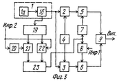
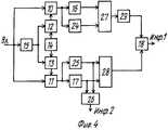
На фиг. 3, 4 приведена функциональная сема линий радиосвязи. In FIG. 3, 4 shows the functional seme of radio communication lines.
Линия радиосвязи содержит на передающей стороне генератор 1 колебаний несущей и тактовой частот, (ГТНЧ) формирователь ортогональной псевдослучайной последовательности (ФОПП), генератор псевдослучайной последовательности 3(ГПП), устройство фазирования 4, первый и второй умножители 5, 6, фазовращатель на 90o 7, фазовый манипулятор 8, схема сложения 9, синтезатор частот 19, фазогенератор 20, первый и второй ключи 21, 22, вторая схема сложения 23, на приемной стороне - первый и второй умножители 10, 11, формирователь ортогональной псевдослучайной последовательности (ФОПП) 12, генератор опорной псевдослучайной последовательности (ГОПП)13, устройство фазирования 14, устройство синхронизации 15, первый и второй полосовые фильтры 16, 17, фазовый детектор 18, третий и четвертый полосовые фильтры 24, 25, схема сравнения 26, первая и вторая схемы выбора максимума 27, 28, фазовращатель на 90o 29.The radio communication line contains on the transmitting side a carrier and
Предлагаемое устройство имеет следующие функциональные связи: на передающей стороне - первый выход генератора колебаний несущей и тактовой частоты 1 соединен со входами ФОПП2, ГПП3 и второй выход этого ГНТЧ соединен со входом синтезатора частот 19, вторые входы ФОПП2и ГПП3 соединены с первым и вторым выходами устройства фазирования 4 соответственно, первый и второй выходы синтезатора частот 19 через первый 21 и второй 22 ключи соответственно соединены с первым и вторым входами второго сумматора 23 соответственно, управляющий вход ключа 22 присоединен ко входу фазоинвертора 20, выход которого соединен с управляющим входом ключа 21, выход ФОПП2 соединен с одним из входов первого умножителя 5, второй вход которого присоединен к выходу фазовращателя на 90o 7, а выход этого умножителя соединен с одним из входов схемы сложения 9, второй вход которой соединен с выходом второго умножителя 6, один из входов которого присоединен к выходу ГПП3, а второй вход этого умножителя соединен с выходом фазового манипулятора 8, вход которого соединен со входом фазовращателя на 90o 7 и с выходом сумматора 23; на приемной стороне - вход устройства синхронизации 15 соединен со входами первого 10 и второго 11 умножителей, второй вход первого умножителя 10 соединен с выходом ФОПП12, один из входов которого присоединен с выходу устройства синхронизации 15 и одному из входов ГОПП13, второй вход которого соединен с одним из выходов устройства фазирования 14, второй выход которого присоединен ко второму входу ФОПП12, выход первого умножителя 10 соединен со входами первого 16 и третьего 24 полосовых фильтров, выходы этих фильтров соединены с первым и вторым входами первой схемы выбора максимума 27 соответственно, выход которого через фазовращатель 29 соединен с одним из выходов фазового детектора 18, второй вход которого присоединен к выходу второй схемы выбора максимума 28, два входа которой соединены соответственно с двумя входами схемы сравнения 26, и кроме того, первый вход схемы выбора максимума 28 соединен с выходом четвертого полосового фильтра 25, а второй вход этой схемы выбора максимума присоединен к выходу второго полосового фильтра 17, входы второго 17 и четвертого 25 полосовых фильтров соединены между собой и с выходом второго умножителя 11; выходы фазового детектора 18 и схемы сравнения 26 являются первым и вторым выходами приемного устройства соответственно.The proposed device has the following functional relationships: on the transmitting side, the first output of the carrier and clock oscillation oscillator 1 is connected to the inputs of FOPP2, GPP3 and the second output of this GNTC is connected to the input of the frequency synthesizer 19, the second inputs of FOPP2 and GPP3 are connected to the first and second outputs of the phasing device 4, respectively, the first and second outputs of the frequency synthesizer 19 through the first 21 and second 22 keys, respectively, are connected to the first and second inputs of the second adder 23, respectively, the control input of the key 22 is Din to the input of the phase inverter 20, the output of which is connected to the control input of the key 21, the output of FOPP2 is connected to one of the inputs of the first multiplier 5, the second input of which is connected to the output of the phase shifter by 90 o 7, and the output of this multiplier is connected to one of the inputs of the addition circuit 9 the second input of which is connected to the output of the second multiplier 6, one of the inputs of which is connected to the output of GPP3, and the second input of this multiplier is connected to the output of the phase manipulator 8, the input of which is connected to the input of the phase shifter by 90 o 7 and to the output of the adder 23; on the receiving side, the input of the synchronization device 15 is connected to the inputs of the first 10 and second 11 multipliers, the second input of the first multiplier 10 is connected to the output of FOPP12, one of the inputs of which is connected to the output of the synchronization device 15 and one of the inputs of the GOPP13, the second input of which is connected to one from the outputs of the phasing device 14, the second output of which is connected to the second input of FOPP12, the output of the first multiplier 10 is connected to the inputs of the first 16 and third 24 bandpass filters, the outputs of these filters are connected to the first and second inputs the first maximum selection circuit 27, respectively, whose output through the phase shifter 29 is connected to one of the outputs of the phase detector 18, the second input of which is connected to the output of the second maximum selection circuit 28, the two inputs of which are connected respectively to the two inputs of the comparison circuit 26, and in addition, the first the input of the maximum selection circuit 28 is connected to the output of the fourth band-pass filter 25, and the second input of this maximum selection circuit is connected to the output of the second band-pass filter 17, the inputs of the second 17 and fourth 25 band-pass filters are connected s among themselves and with the output of the second multiplier 11; the outputs of the phase detector 18 and the comparison circuit 26 are the first and second outputs of the receiving device, respectively.
Предлагаемое устройство работает следующим образом. The proposed device operates as follows.
В передатчике генератор несущей и тактовой частот 1 (ГНТЧ) формирует две частоты: тактовую для ФОПП2 и ГПП3 и несущую частоту сигнала, подаваемую на синтезатор частот 19. Тактовая частота с выхода ГНТЧ1 поступает на вход ФОПП2 и ГПП3, которые вырабатывают двоичные псевдослучайные последовательности - ПСП. Эти ПСП представляют собой совокупности биполярных импульсов постоянного тока одинаковой величины и длительности, которая определяется величиной тактовой частоты. Законы образования ПСП выбираются такими, чтобы обеспечить малую взаимную корреляцию между псевдослучайными последовательностями ФОПП2 и ГПП3 при любом фазовом сдвиге между ними (квазиортогональные двоичные ПСП). Это условие необходимо для их эффективного разделения и подавления эхо-сигналов в приемнике. In the transmitter, the carrier and clock frequency generator 1 (GNTC) generates two frequencies: the clock frequency for FOPP2 and GPP3 and the carrier frequency of the signal supplied to the
Устройство фазирования 4 устанавливает сдвиговые регистры ФОПП2 и ГПП3 в одинаковое начальное состояние, что обеспечивает связь по фазе их псевдослучайных последовательностей. Устройство фазирования 4 состоит из дешифраторов начальных состояний ФОПП2 и ГПП3 и импульсной схемы фазирования, которая обеспечивает совмещение их начальных состояний по фазе. Двоичная ПСП с выхода ФОПП2 поступает на умножитель 5, на второй вход которого через фазовращатель на 90o 7 поступает колебание несущей частоты с выхода сумматора 23. Со второго выхода ГНТЧ1 колебание несущей частоты поступает на вход синтезатора частот 19, где из этого колебания формируется первая f1, и вторая f2 несущие частоты и которые через первый ключ 21 и второй ключ 22 соответственно коммутируются на входы второго суммирующего устройства 23. Управление ключами 21 и 22 производится сигналом информации "ИНФ2", причем на первый ключ - через фазоинвертор 20. С выхода второго суммирующего устройства 23 несущие частоты f1 и f2 поступают на входы фазового манипулятора 8 и фазовращателя на 90o 7. В умножителе 5 сигнал двоичной ПСП, поступающий на первый вход умножителя, умножается на сигнал несущей частоты, поступающего на второй вход умножителя. В результате на входе умножителя 5 образуется сигнал, представляющий колебание несущей частоты с постоянной амплитудой, манипулированное по фазе на 180o по закону двоичной ПСП. Двоичная ПСП с выхода ГПП3 поступает на умножитель 6, на второй вход которого поступает сигнал с фазового манипулятора 8. На входе умножителя 6, таким образом, образуется сигнал, представляющий собой колебание несущей частоты с постоянной амплитудой, манипулированное по фазе на 180o по закону двоичной ПСП. В зависимости от знака передаваемой информации "ИНФ1" фазовый манипулятор 8 осуществляет поворот фазы несущей частоты сигнала на выходе умножителя 6 относительно несущей частоты сигнала на выходе умножителя 5 на 0 или 180o. Таким образом, в зависимости от знака передаваемой информации несущие частоты этих сигналов сдвинуты между собой по фазе. С выходов умножителей 5 и 6 сигналы поступают на схему сложения 9, которая образует выходной сигнал передатчика, представляющий собой колебания несущих частот f1 и f2 с постоянной амплитудой, манипулированные по фазе на 0o, 90o, 180o и 270o, причем моменты манипуляции и порядок следования этих величин определяются соотношением знаков элементов двоичных ПСП ФОПП2 и ГПП3 и передаваемой разностью фаз ИНФ1. Со схемы сложения 9 сигнал поступает в высокочастотный передатчик и излучается в эфир. Принимаемый сигнал с выхода высокочастотного приемника поступает на умножители 10 и 11, аналогичные умножители 5 и 6 передатчика. В умножителе 10 принимаемый сигнал умножается на двоичную ПСП, которую вырабатывает ФОПП12, аналогичный ФОПП2 передатчика. Сигнал с выхода умножителя 10 поступает на полосовые фильтры 16, 4, которые настроены соответственно на частоты f1 и f2 и в зависимости от того, на какой частоте (f1 или f2) был принят сигнал в данный момент, через тот фильтр и проходит принятый сигнал. С выходов фильтров 16 и 24 сигнал поступает на схему выбора максимума 27, (точнее сигнал в данный момент поступает только с одного из этих фильтров, а с другого - только шум), где производится выбор наибольшего значения из двух сигналов, и это и будет полезный сигнал, снятый с одного из фильтров. Со схемы выбора максимума 27 сигнал через фазовращатель на 90o 29 поступает на один из входов фазового детектора 18.The
В умножителе 11 принимаемый сигнал умножается на двоичную ПСП, которую формирует ГОПП13, аналогичную ГПП3 передатчика. Сигнал с выхода умножителя 11 поступает на полосовые фильтры 11, 25, настроенные, как и фильтры 16, 24, на частоты f1 и f2. С фильтров 17, 25 сигнал поступает на входы схемы сравнения 26, с выхода который снимается сигнал "ИНФ2". С этих же фильтров 17, 25 сигнал, кроме того, поступает на входы второй схемы выбора максимума 28, аналогичной схеме выбора максимума 27. С выхода второй схемы выбора максимума 28 сигнал поступает на второй вход фазового детектора 18, который измеряет информационную разность фаз между ними и с выхода которого и снимается сигнал "ИНФ1". Устройство фазирования 14, аналогичное устройству фазирования 4 передатчика, обеспечивает связь по фазе выходных последовательностей ФОПП12 и ГОПП13, соответствующую связи по фазе последовательностей ФОПП2 и ГПП3 передатчика.In the
Двоичные ПСП, вырабатываемые генераторами в приемнике, синхронизируются с двоичными ПСП принимаемого сигнала с помощью устройства синхронизации 15. В качестве устройства синхронизации 15 могут быть использованы известные устройства синхронизации, обеспечивающие синхронизм местных сигналов приемника с одним из сильнейших лучей принимаемого моноголучевого сигнала на основе анализа функции взаимной корреляции принимаемого и местного сигналов. The binary SRPs generated by the generators in the receiver are synchronized with the binary SRPs of the received signal using the
Как известно, при использовании широкополосных сигналов, при этом может быть обеспечено эффективное подавление мешающих лучей либо сложение нескольких выделенных наиболее сильных лучей, а также подавление сосредоточенных помех. As you know, when using broadband signals, this can be achieved by efficiently suppressing interfering rays or by adding up several of the strongest rays identified, as well as suppressing concentrated noise.
Таким образом, если в устройстве-прототипе при использовании двух ортогональных каналов передается только одна основная информация, то в предлагаемом устройстве при использовании тех же двух ортогональных каналов передается помимо основной еще и дополнительная информация, которая может быть использована как служебная или для каких-либо других целей. Это позволяет во многих случаях отказаться от организации специального канала передачи служебной информации. Thus, if in the prototype device, when using two orthogonal channels, only one basic information is transmitted, then in the proposed device when using the same two orthogonal channels, additional information is transmitted in addition to the main one, which can be used as official or for any other goals. This allows in many cases to abandon the organization of a special channel for transferring service information.
Claims (1)
Priority Applications (1)
| Application Number | Priority Date | Filing Date | Title |
|---|---|---|---|
| RU99100583A RU2160503C2 (en) | 1999-01-10 | 1999-01-10 | Radio communication line |
Applications Claiming Priority (1)
| Application Number | Priority Date | Filing Date | Title |
|---|---|---|---|
| RU99100583A RU2160503C2 (en) | 1999-01-10 | 1999-01-10 | Radio communication line |
Publications (2)
| Publication Number | Publication Date |
|---|---|
| RU2160503C2 true RU2160503C2 (en) | 2000-12-10 |
| RU99100583A RU99100583A (en) | 2000-12-27 |
Family
ID=20214585
Family Applications (1)
| Application Number | Title | Priority Date | Filing Date |
|---|---|---|---|
| RU99100583A RU2160503C2 (en) | 1999-01-10 | 1999-01-10 | Radio communication line |
Country Status (1)
| Country | Link |
|---|---|
| RU (1) | RU2160503C2 (en) |
Cited By (4)
| Publication number | Priority date | Publication date | Assignee | Title |
|---|---|---|---|---|
| RU2206180C2 (en) * | 2001-07-24 | 2003-06-10 | Закрытое акционерное общество "Кодофон" | Device for initial synchronization of pseudorandom signal receiver |
| RU2219660C2 (en) * | 2002-03-22 | 2003-12-20 | Федеральное государственное унитарное предприятие "Воронежский научно-исследовательский институт связи" | Radio link |
| RU2308155C2 (en) * | 2005-05-13 | 2007-10-10 | Открытое акционерное общество "Концерн "Созвездие " | Radio communication line with increased concealment of transferred information |
| RU2565530C1 (en) * | 2014-09-16 | 2015-10-20 | Открытое акционерное общество "Омский научно-исследовательский институт приборостроения" (ОАО "ОНИИП") | Method of multifrequency modulation of signal |
Citations (4)
| Publication number | Priority date | Publication date | Assignee | Title |
|---|---|---|---|---|
| US300946A (en) * | 1884-06-24 | Pulp-board for roofing purposes | ||
| US3864633A (en) * | 1972-08-23 | 1975-02-04 | Sperry Rand Corp | Angle diversity communication system |
| US4078818A (en) * | 1977-01-25 | 1978-03-14 | Donnelly Frank R | Convertible flatbed truck |
| DE2414828B2 (en) * | 1973-03-27 | 1979-07-26 | The Marconi Co. Ltd., Chelmsford, Essex (Grossbritannien) | Diversity circuitry |
-
1999
- 1999-01-10 RU RU99100583A patent/RU2160503C2/en active
Patent Citations (4)
| Publication number | Priority date | Publication date | Assignee | Title |
|---|---|---|---|---|
| US300946A (en) * | 1884-06-24 | Pulp-board for roofing purposes | ||
| US3864633A (en) * | 1972-08-23 | 1975-02-04 | Sperry Rand Corp | Angle diversity communication system |
| DE2414828B2 (en) * | 1973-03-27 | 1979-07-26 | The Marconi Co. Ltd., Chelmsford, Essex (Grossbritannien) | Diversity circuitry |
| US4078818A (en) * | 1977-01-25 | 1978-03-14 | Donnelly Frank R | Convertible flatbed truck |
Cited By (4)
| Publication number | Priority date | Publication date | Assignee | Title |
|---|---|---|---|---|
| RU2206180C2 (en) * | 2001-07-24 | 2003-06-10 | Закрытое акционерное общество "Кодофон" | Device for initial synchronization of pseudorandom signal receiver |
| RU2219660C2 (en) * | 2002-03-22 | 2003-12-20 | Федеральное государственное унитарное предприятие "Воронежский научно-исследовательский институт связи" | Radio link |
| RU2308155C2 (en) * | 2005-05-13 | 2007-10-10 | Открытое акционерное общество "Концерн "Созвездие " | Radio communication line with increased concealment of transferred information |
| RU2565530C1 (en) * | 2014-09-16 | 2015-10-20 | Открытое акционерное общество "Омский научно-исследовательский институт приборостроения" (ОАО "ОНИИП") | Method of multifrequency modulation of signal |
Similar Documents
| Publication | Publication Date | Title |
|---|---|---|
| US4912722A (en) | Self-synchronous spread spectrum transmitter/receiver | |
| US4280222A (en) | Receiver and correlator switching method | |
| US3916313A (en) | PSK-FSK spread spectrum modulation/demodulation | |
| RU2279183C2 (en) | Method for transferring information in communication system with broadband signals | |
| RU2188516C1 (en) | Quaternary-coded radio signal transmission system | |
| RU2160503C2 (en) | Radio communication line | |
| RU2127486C1 (en) | Method and device for transmitting messages by broad-band signals | |
| RU2085039C1 (en) | Radio communication system | |
| RU2691384C1 (en) | Method of transmitting information by wideband signals | |
| RU2193278C1 (en) | Radio communication link | |
| RU2219660C2 (en) | Radio link | |
| RU2233028C2 (en) | Space-division radio link | |
| RU2240653C1 (en) | Time-division multiple access data transfer system | |
| RU2358401C1 (en) | Device for transmitting and receiving discrete messages using signals with direct spreading and autocorrelation compression of spectrum | |
| RU2113768C1 (en) | Device for digital information exchange | |
| RU2115236C1 (en) | Communication system with wide-band signals | |
| RU2204208C2 (en) | Multiparametric-modulation radio communication line | |
| RU2308155C2 (en) | Radio communication line with increased concealment of transferred information | |
| RU2731681C1 (en) | Method of forming noise-like phase-shift keyed signals | |
| RU2149506C1 (en) | Radio communication line with spatial discrimination of signals | |
| RU2033692C1 (en) | Transceiver of wide band signals with increased information security | |
| RU2161865C2 (en) | Radio communication line | |
| SU930719A1 (en) | Device for correlation recepion of complex phase shift keying signals | |
| RU42375U1 (en) | DEVICE FOR RECEIVING BROADBAND SIGNALS IN SPACE COMMUNICATION SYSTEMS | |
| JP2966810B2 (en) | Spread spectrum multiplexing communication equipment |