RU2154528C2 - Device and method for manufacture of member with cellular structure, particularly, carrier-body of catalytic neutralizer - Google Patents
Device and method for manufacture of member with cellular structure, particularly, carrier-body of catalytic neutralizer Download PDFInfo
- Publication number
- RU2154528C2 RU2154528C2 RU98101118/12A RU98101118A RU2154528C2 RU 2154528 C2 RU2154528 C2 RU 2154528C2 RU 98101118/12 A RU98101118/12 A RU 98101118/12A RU 98101118 A RU98101118 A RU 98101118A RU 2154528 C2 RU2154528 C2 RU 2154528C2
- Authority
- RU
- Russia
- Prior art keywords
- axis
- rotation
- twisting
- honeycomb structure
- profile
- Prior art date
Links
- 238000000034 method Methods 0.000 title claims abstract description 24
- 238000004519 manufacturing process Methods 0.000 title claims abstract description 22
- 230000003197 catalytic effect Effects 0.000 title claims description 7
- 210000003850 cellular structure Anatomy 0.000 title 1
- 229910052751 metal Inorganic materials 0.000 claims abstract description 24
- 239000002184 metal Substances 0.000 claims abstract description 23
- 239000012530 fluid Substances 0.000 claims abstract description 12
- 230000009471 action Effects 0.000 claims description 6
- 230000006835 compression Effects 0.000 claims description 2
- 238000007906 compression Methods 0.000 claims description 2
- 239000007787 solid Substances 0.000 abstract description 2
- 239000000126 substance Substances 0.000 abstract description 2
- 230000001413 cellular effect Effects 0.000 abstract 1
- 230000000694 effects Effects 0.000 abstract 1
- 230000008569 process Effects 0.000 description 13
- 238000005452 bending Methods 0.000 description 8
- 230000008901 benefit Effects 0.000 description 2
- 239000003054 catalyst Substances 0.000 description 2
- 230000015271 coagulation Effects 0.000 description 2
- 238000005345 coagulation Methods 0.000 description 2
- 230000001419 dependent effect Effects 0.000 description 2
- 230000008859 change Effects 0.000 description 1
- 238000010276 construction Methods 0.000 description 1
- 238000005265 energy consumption Methods 0.000 description 1
- 239000007789 gas Substances 0.000 description 1
- 239000000463 material Substances 0.000 description 1
- 230000007246 mechanism Effects 0.000 description 1
Images


Classifications
-
- B01J35/56—
-
- F—MECHANICAL ENGINEERING; LIGHTING; HEATING; WEAPONS; BLASTING
- F01—MACHINES OR ENGINES IN GENERAL; ENGINE PLANTS IN GENERAL; STEAM ENGINES
- F01N—GAS-FLOW SILENCERS OR EXHAUST APPARATUS FOR MACHINES OR ENGINES IN GENERAL; GAS-FLOW SILENCERS OR EXHAUST APPARATUS FOR INTERNAL COMBUSTION ENGINES
- F01N3/00—Exhaust or silencing apparatus having means for purifying, rendering innocuous, or otherwise treating exhaust
- F01N3/08—Exhaust or silencing apparatus having means for purifying, rendering innocuous, or otherwise treating exhaust for rendering innocuous
- F01N3/10—Exhaust or silencing apparatus having means for purifying, rendering innocuous, or otherwise treating exhaust for rendering innocuous by thermal or catalytic conversion of noxious components of exhaust
- F01N3/24—Exhaust or silencing apparatus having means for purifying, rendering innocuous, or otherwise treating exhaust for rendering innocuous by thermal or catalytic conversion of noxious components of exhaust characterised by constructional aspects of converting apparatus
- F01N3/28—Construction of catalytic reactors
- F01N3/2803—Construction of catalytic reactors characterised by structure, by material or by manufacturing of catalyst support
- F01N3/2807—Metal other than sintered metal
- F01N3/281—Metallic honeycomb monoliths made of stacked or rolled sheets, foils or plates
-
- B—PERFORMING OPERATIONS; TRANSPORTING
- B21—MECHANICAL METAL-WORKING WITHOUT ESSENTIALLY REMOVING MATERIAL; PUNCHING METAL
- B21D—WORKING OR PROCESSING OF SHEET METAL OR METAL TUBES, RODS OR PROFILES WITHOUT ESSENTIALLY REMOVING MATERIAL; PUNCHING METAL
- B21D53/00—Making other particular articles
- B21D53/02—Making other particular articles heat exchangers or parts thereof, e.g. radiators, condensers fins, headers
- B21D53/027—Making other particular articles heat exchangers or parts thereof, e.g. radiators, condensers fins, headers by helically or spirally winding elongated elements
-
- F—MECHANICAL ENGINEERING; LIGHTING; HEATING; WEAPONS; BLASTING
- F01—MACHINES OR ENGINES IN GENERAL; ENGINE PLANTS IN GENERAL; STEAM ENGINES
- F01N—GAS-FLOW SILENCERS OR EXHAUST APPARATUS FOR MACHINES OR ENGINES IN GENERAL; GAS-FLOW SILENCERS OR EXHAUST APPARATUS FOR INTERNAL COMBUSTION ENGINES
- F01N3/00—Exhaust or silencing apparatus having means for purifying, rendering innocuous, or otherwise treating exhaust
- F01N3/08—Exhaust or silencing apparatus having means for purifying, rendering innocuous, or otherwise treating exhaust for rendering innocuous
- F01N3/10—Exhaust or silencing apparatus having means for purifying, rendering innocuous, or otherwise treating exhaust for rendering innocuous by thermal or catalytic conversion of noxious components of exhaust
- F01N3/24—Exhaust or silencing apparatus having means for purifying, rendering innocuous, or otherwise treating exhaust for rendering innocuous by thermal or catalytic conversion of noxious components of exhaust characterised by constructional aspects of converting apparatus
- F01N3/28—Construction of catalytic reactors
-
- F—MECHANICAL ENGINEERING; LIGHTING; HEATING; WEAPONS; BLASTING
- F01—MACHINES OR ENGINES IN GENERAL; ENGINE PLANTS IN GENERAL; STEAM ENGINES
- F01N—GAS-FLOW SILENCERS OR EXHAUST APPARATUS FOR MACHINES OR ENGINES IN GENERAL; GAS-FLOW SILENCERS OR EXHAUST APPARATUS FOR INTERNAL COMBUSTION ENGINES
- F01N2330/00—Structure of catalyst support or particle filter
- F01N2330/02—Metallic plates or honeycombs, e.g. superposed or rolled-up corrugated or otherwise deformed sheet metal
- F01N2330/04—Methods of manufacturing
Abstract
Description
Настоящее изобретение относится к устройству и способу для изготовления элемента с сотовой структурой, имеющего множество каналов для прохождения текучей среды, в частности корпуса- носителя каталитического нейтрализатора. The present invention relates to an apparatus and method for manufacturing a cell structure member having a plurality of fluid paths, in particular a catalyst support body.
Для снижения выбросов вредных веществ, в частности в отработавших газах транспортных средств, применяются каталитические нейтрализаторы с корпусами-носителями. В качестве таких корпусов-носителей могут использоваться металлические элементы с сотовой структурой. Элемент с сотовой структурой состоит из набранного в пакет множества по меньшей мере частично структурированных металлических листов. Этот пакет свернут в рулон путем его скручивания в противоположных направлениях вокруг центральной зоны. Такое выполнение элемента с сотовой структурой известно, например, из патента США 4923109. To reduce emissions of harmful substances, in particular in the exhaust gases of vehicles, catalytic converters with carrier bodies are used. As such carrier bodies metal elements with a honeycomb structure can be used. A honeycomb cell consists of a plurality of at least partially structured metal sheets stacked in a bag. This bag is rolled up by twisting it in opposite directions around the central zone. Such an embodiment of an element with a honeycomb structure is known, for example, from US Pat. No. 4,923,109.
Из заявки WO 90/03220 известен металлический корпус-носитель каталитического нейтрализатора для транспортных средств, который состоит по меньшей мере из частично структурированных металлических листов. Этот корпус-носитель включает по меньшей мере три пакета металлических листов, причем по меньшей мере три из них сложены пополам по соответствующей линии сгиба в центральной зоне элемента с сотовой структурой и в таком состоянии свернуты в рулон путем их скручивания друг относительно друга в одном направлении вокруг центральной зоны, в которой находятся линии сгиба. From the application WO 90/03220, a metal catalytic converter vehicle carrier body is known which consists of at least partially structured metal sheets. This carrier body includes at least three packs of metal sheets, at least three of which are folded in half along the corresponding fold line in the central area of the honeycomb cell and, in this state, are rolled up by twisting relative to each other in one direction around the central zone in which the fold lines are located.
Из уровня техники известны также устройства для изготовления таких корпусов-носителей каталитических нейтрализаторов, включающие поворачивающееся вокруг оси и воздействующее на каждый пакет вильчатое скручивающее приспособление и замыкающиеся в цельную форму профильные сегменты. Внутренний контур замкнутой формы соответствует наружному контуру элемента с сотовой структурой в его окончательно скрученном состоянии. Наиболее частой формой, которую имеют элементы с сотовой структурой, является цилиндрическая. С целью обеспечить свертывание в рулон пакетов вокруг центральной зоны профильные сегменты перемещаются по направлению к пакету таким образом, что во время поворота вильчатого скручивающего приспособления пакет, соответственно пакеты прилегает (ют) к краю профильных сегментов, и этот край образует контропору. В конце процесса изготовления форма полностью смыкается, и элементу с сотовой структурой, таким образом, придается его окончательная форма. The prior art also known devices for the manufacture of such carrier bodies of catalytic converters, including a pivoting twisting device that rotates around an axis and acts on each bag and integrates profile segments that are closed in a single shape. The inner contour of a closed shape corresponds to the outer contour of an element with a honeycomb structure in its finally twisted state. The most common shape that honeycomb cells have is cylindrical. In order to ensure that the packages are rolled up around the central zone, the profile segments move towards the package so that while the fork twist device is turning, the package, respectively, the packages adheres to the edge of the profile segments, and this edge forms a counter support. At the end of the manufacturing process, the form completely closes, and the element with the honeycomb structure is thus given its final shape.
Известные устройства имеют два профильных сегмента, которые могут перемещаться прямолинейно по направлению друг к другу и друг от друга. Во время процесса смыкания формы существует опасность, что по меньшей мере один профильный сегмент будет продолжать двигаться против направления движения участка пакета, который еще подлежит свертыванию в рулон, что может привести к нежелательной деформации пакета, соответственно пакетов. Деформация приводит к тому, что отдельные листы частично изгибаются. Вследствие этого структура готового элемента нарушается. Во-первых, страдает прочность элемента с сотовой структурой, а во-вторых, происходит локальное изменение поперечных сечений каналов. Known devices have two profile segments that can move in a straight line towards each other and from each other. During the mold closing process, there is a danger that at least one profile segment will continue to move against the direction of movement of the portion of the packet, which is still to be rolled up, which can lead to undesirable deformation of the packet, respectively packets. Deformation leads to the fact that individual sheets are partially bent. As a result, the structure of the finished element is violated. Firstly, the strength of an element with a honeycomb structure suffers, and secondly, there is a local change in the cross sections of the channels.
Исходя из сказанного выше, в основу изобретения была положена задача усовершенствовать известное устройство для изготовления элемента с сотовой структурой таким образом, чтобы во время процесса изготовления не возникала опасность деформации пакетов, соответственно отдельных металлических листов. Далее необходимо разработать способ изготовления элемента с сотовой структурой, предотвращающий деформацию отдельных пакетов. Based on the foregoing, the basis of the invention was the task of improving the known device for manufacturing an element with a honeycomb structure so that during the manufacturing process there is no danger of deformation of the packages, respectively, of individual metal sheets. Next, it is necessary to develop a method of manufacturing an element with a honeycomb structure, preventing the deformation of individual packages.
Согласно изобретению эта задача решается с помощью устройства с отличительными признаками п. 1 формулы изобретения. Предпочтительные варианты выполнения устройства представлены в зависимых пп. 2-18. Предлагаемые согласно изобретению способы изготовления элемента с сотовой структурой описаны в пп. 19 и 20. Предпочтительный вариант осуществления способа представлен в зависимом п. 21. According to the invention, this problem is solved using a device with the hallmarks of paragraph 1 of the claims. Preferred embodiments of the device are presented in dependent claims. 2-18. Proposed according to the invention methods of manufacturing an element with a honeycomb structure are described in paragraphs. 19 and 20. A preferred embodiment of the method is presented in
Предлагаемое устройство для изготовления элемента с сотовой структурой, состоящего из множества набранных по меньшей мере в один пакет по меньшей мере частично структурированных металлических листов, образующих множество каналов для прохождения текучей среды, включает форму, которая содержит по меньшей мере два профильных сегмента. Каждый профильный сегмент может поворачиваться вокруг соответствующей оси, проходящей параллельно оси скручивающего приспособления, против направления поворота последнего. Благодаря повороту каждого профильного сегмента против направления поворота скручивающего приспособления предотвращается расплющивание одного или нескольких пакетов при смыкании формы. При наличии более двух пакетов количество профильных сегментов в устройстве, которые могут поворачиваться против направления поворота скручивающего приспособления предпочтительно соответствует количеству пакетов. Оси поворота профильных сегментов расположены преимущественно эквидистантно относительно друг друга на огибающей готового элемента с сотовой структурой. The proposed device for the manufacture of an element with a honeycomb structure, consisting of a plurality of at least partially structured metal sheets assembled in at least one packet and forming a plurality of channels for the passage of a fluid, includes a mold that contains at least two profile segments. Each profile segment can rotate around a corresponding axis passing parallel to the axis of the twisting device, against the direction of rotation of the latter. Thanks to the rotation of each profile segment against the direction of rotation of the twisting device, the flattening of one or more packets is prevented when the mold closes. If there are more than two packages, the number of profile segments in the device that can rotate against the direction of rotation of the twisting device preferably corresponds to the number of packages. The axis of rotation of the profile segments are mainly equidistant relative to each other on the envelope of the finished element with a honeycomb structure.
На набранные в пакет металлические листы элемента с сотовой структурой действует высокая нагрузка, которая обусловлена конструкцией известного устройства для изготовления такого элемента. Нагрузка на листы возникает, в частности, в результате того, что контропора расположена на некотором расстоянии от центра приложения сил. Система "контропора - пакет листов - центр приложения сил" сравнима с односторонне закрепленной наборной листовой рессорой. Как это имеет место в таких наборных листовых рессорах, между отдельными слоями пакета возникают силы трения. Эти силы трения приводят при свертывании в рулон пакета (ов) к повышенному расходу энергии. Кроме того, изгибается еще не свернутый участок каждого пакета, что обусловливает работу боковой деформации при смятии пакета. The metal sheets of an element with a honeycomb structure packed into a bag are subjected to a high load, which is caused by the construction of a known device for manufacturing such an element. The load on the sheets occurs, in particular, as a result of the fact that the counter support is located at some distance from the center of application of forces. The system "counter support - a package of sheets - the center of application of forces" is comparable to a unilaterally fixed type-setting leaf spring. As is the case in such stacked leaf springs, friction forces arise between the individual layers of the bag. These friction forces, when coagulated into a roll of bag (s), increase energy consumption. In addition, the yet unfolded portion of each packet is bent, which makes the lateral deformation work when the packet is crushed.
Основная идея работы устройства и предпочтительных вариантов осуществления способов заключается в том, что изготовление элемента с сотовой структурой, имеющего множество каналов для прохождения текучей среды, в частности корпуса-носителя каталитического нейтрализатора, более технологично в том случае, когда контропора непосредственно прилегает к свернутому в рулон пакету, соответственно к свернутым в рулон пакетам. Еще не свернутый участок каждого пакета свободен. Поэтому в отличие от уровня техники никаких нагрузок на этом еще не скрученном участке пакета не возникает. Отсутствует, следовательно, и изгибающая нагрузка на этом еще не свернутом участке пакета. The main idea of the operation of the device and the preferred embodiments of the methods is that the manufacture of an element with a honeycomb structure having many channels for the passage of fluid, in particular the carrier housing of the catalytic converter, is more technologically advanced when the counter support is directly adjacent to a rolled coil package, respectively, to rolled packages. The yet unfolded portion of each packet is free. Therefore, in contrast to the state of the art, no loads arise on this yet untwisted portion of the packet. There is, therefore, no bending load on this unfolded portion of the bag.
Эта основная идея реализована согласно п. 5 формулы изобретения в устройстве для изготовления элемента с сотовой структурой, имеющего множество каналов для прохождения текучей среды, в частности каталитического нейтрализатора, состоящего из набранного в пакет множества по меньшей мере частично структурированных металлических листов, при этом устройство включает поворачивающееся вокруг оси и действующее на пакет вильчатое скручивающее приспособление и замыкающиеся в цельную форму профильные сегменты, причем ось поворота расположена на образующем контропору конце профильного сегмента, а каждая контропора может перемещаться по направлению к оси и от нее. В этом устройстве контропора во время свертывания листов друг вокруг друга постоянно прилегает к пакету. Во время процесса свертывания радиальный размер уже скрученного пакета увеличивается. С целью учесть этот процесс контропора выполнена таким образом, что она может перемещаться к оси скручивающего приспособления и от нее. Контропора может прилегать к пакету с определенным прижимным усилием. This basic idea is implemented according to
Для изготовления элемента с сотовой структурой по меньшей мере из трех пакетов, каждый из которых состоит из множества по меньшей мере частично структурированных металлических листов и которые скручены в одном направлении друг вокруг друга, предлагается устройство, в котором количество профильных сегментов формы соответствует количеству пакетов. Каждый профильный сегмент закреплен на оси поворота, проходящей параллельно центральной оси, и образует на конце соответственно одну контропору. Профильные сегменты могут поворачиваться против направления поворота скручивающего приспособления. Каждая контропора может перемещаться к оси скручивающего приспособления и от нее. С помощью такого устройства может быть изготовлен описанный в WO 90/03220 элемент с сотовой структурой. For the manufacture of an element with a honeycomb structure of at least three packages, each of which consists of many at least partially structured metal sheets and which are twisted in one direction around each other, a device is proposed in which the number of profile segments of the shape corresponds to the number of packages. Each profile segment is fixed on the axis of rotation, which runs parallel to the central axis, and forms at the end, respectively, one counter-support. The profile segments can rotate against the direction of rotation of the twisting device. Each counter support can move to and from the axis of the twisting device. With such a device, a honeycomb cell described in WO 90/03220 can be manufactured.
Согласно еще одному предпочтительному варианту предлагаемое устройство имеет опорную плиту с направляющими пазами, проходящими радиально к центру. В каждом направляющем пазу установлен с возможностью скольжения в нем болт, образующий ось поворота. Каждый направляющий паз имеет многоугольное поперечное сечение. Направляющий паз предпочтительно выполнять с Т-образным поперечным сечением или поперечным сечением в форме ласточкина хвоста. Болт имеет соответствующую головку, вставленную в направляющий паз. Направляющие пазы необязательно выполнять в цельной опорной плите. Они также могут быть образованы несколькими соответственно сформованными плитами. According to another preferred embodiment, the proposed device has a base plate with guide grooves extending radially to the center. In each guide groove is mounted with the possibility of sliding in it a bolt forming an axis of rotation. Each guide groove has a polygonal cross section. The guide groove is preferably made with a T-shaped cross section or a dovetail shape. The bolt has a corresponding head inserted into the guide groove. Guide grooves do not have to be in a solid base plate. They can also be formed by several suitably molded tiles.
Перемещение контропор в направлении к оси и от нее происходит преимущественно с помощью электродвигателя. Для этой цели особенно пригоден шаговый двигатель, поскольку он позволяет точно регулировать перемещение контропоры относительно уже свернутых в рулон пакетов. Между электродвигателем и контропорой может быть предусмотрен соответствующий редуктор. Можно использовать и другие механизмы, например, зубчатую рейку, соединенную одним концом с контропорой и входящую в зацепление с соответствующим зубчатым колесом электродвигателя. The movement of the counter supports towards the axis and away from it occurs mainly with the help of an electric motor. A stepper motor is particularly suitable for this purpose, since it allows you to precisely control the movement of the counter support relative to packages already rolled up. An appropriate gearbox may be provided between the electric motor and the counter-support. You can use other mechanisms, for example, a gear rack connected at one end with a counter support and engaged with the corresponding gear wheel of the electric motor.
В предпочтительном варианте выполнения устройства каждая контропора соединена с поршневым блоком. Поршневой блок может иметь гидравлический или пневматический привод. При этом можно применять известные стандартизованные поршневые блоки. In a preferred embodiment of the device, each counter support is connected to a piston unit. The piston unit may have a hydraulic or pneumatic drive. In this case, well-known standardized piston blocks can be used.
Согласно еще одному предпочтительному варианту устройства предлагается перемещать поворотные оси в направлении от центральной оси против действия пружинной силы. Такая пружинная сила может создаваться пружиной растяжения или пружиной сжатия либо парой таких пружин. В предпочтительном варианте пружинную силу, с которой контропора прилегает к скрученному пакету, можно регулировать. Благодаря этому устройство можно адаптировать к различным формам и исходным материалам элемента с сотовой структурой. Предпочтительно пружинная сила имеет дегрессивную характеристику. Это основано на том, что сила, с которой контропора прилегает к пакету, вследствие большего радиуса изгиба может быть меньше, чем в центре изогнутого пакета. Преимущество применения пружин состоит также в том, что они представляют собой стандартизованные детали, которые обеспечивают безопасную и надежную работу. According to another preferred embodiment of the device, it is proposed to move the rotary axes in the direction from the central axis against the action of the spring force. Such a spring force can be generated by a tensile spring or a compression spring or a pair of such springs. In a preferred embodiment, the spring force with which the counter support is adjacent to the twisted bag can be adjusted. Thanks to this, the device can be adapted to various forms and source materials of an element with a honeycomb structure. Preferably, the spring force has a degressive characteristic. This is based on the fact that the force with which the counter support is adjacent to the packet, due to the larger bending radius, may be less than in the center of the curved packet. The advantage of using springs is also that they are standardized parts that ensure safe and reliable operation.
Для замыкания формы каждый профильный сегмент соединен с приводным блоком, который поворачивает этот сегмент вокруг соответствующей оси. При этом приводным блоком может быть поршневой блок с гидравлическим или пневматическим приводом. To close the form, each profile segment is connected to the drive unit, which rotates this segment around the corresponding axis. In this case, the drive unit may be a piston unit with a hydraulic or pneumatic drive.
Ниже описывается способ изготовления элемента с сотовой структурой, имеющего множество каналов для прохождения текучей среды, образованных множеством по меньшей мере частично структурированных металлических листов. Согласно этому способу сначала набирают в пакет множество по меньшей мере частично структурированных металлических листов. Этот пакет помещают в открытую форму. В центральной зоне пакета и формы пакет удерживается скручивающим приспособлением. Скручивающее приспособление может быть выполнено вильчатым. Затем пакет свертывается в рулон скручивающим приспособлением. Путем поворота профильных сегментов против направления поворота скручивающего приспособления форма смыкается. Форма может смыкаться лишь по достижении заданной степени скручивания. Пакет необязательно должен быть свернут в рулон полностью. Процесс замыкания формы может начинаться уже тогда, когда размер еще не свернутого участка пакета меньше длины периметра профильного сегмента или равен ей. Если процесс замыкания формы начинается уже при указанных выше условиях, то процесс скручивания осуществляет каждый сегмент, поскольку смыкающиеся сегменты давят на еще не свернутые в рулон участки в сторону оси. Этим способом изготавливается элемент с сотовой структурой, известный из EP 0245737. Такой элемент с сотовой структурой известен специалистам в данной области техники под обозначением S-Kat. The following describes a method of manufacturing a cell structure member having a plurality of fluid channels formed by a plurality of at least partially structured metal sheets. According to this method, a plurality of at least partially structured metal sheets are first stacked. This bag is placed in an open mold. In the central area of the bag and shape, the bag is held by a twisting device. The twisting device can be made forked. Then the package is rolled up with a twisting device. By turning the profile segments against the direction of rotation of the twisting device, the form closes. The form can close only when the specified degree of twisting is achieved. The bag does not have to be rolled up completely. The process of closing the form can begin even when the size of the package, which has not yet been folded, is less than or equal to the length of the perimeter of the profile segment. If the process of closing the form begins already under the above conditions, then the twisting process carries out each segment, since the closing segments press on the sections not yet rolled up in the direction of the axis. In this manner, a honeycomb cell known from EP 0245737 is manufactured. Such a honeycomb cell is known to those skilled in the art under the designation S-Kat.
Для изготовления элемента с сотовой структурой, имеющего множество каналов для прохождения текучей среды, образованных множеством по меньшей мере частично структурированных металлических листов, и описанного, например, в заявке WO 89/03220, предлагается набирать в несколько пакетов множество по меньшей мере частично структурированных металлических листов. Каждый пакет складывают пополам по линии его сгиба. После этого каждый пакет помещают в открытую форму, где он удерживается скручивающим приспособлением в центральной зоне. To produce a honeycomb structure member having a plurality of fluid channels formed by a plurality of at least partially structured metal sheets and described, for example, in WO 89/03220, it is proposed to stack a plurality of at least partially structured metal sheets in several packages. . Each bag is folded in half along its fold line. After that, each bag is placed in an open form, where it is held by a twisting device in the central zone.
Согласно еще одному предпочтительному варианту способа предлагается после захвата пакета скручивающим приспособлением располагать по обе стороны пакета в центральной зоне напротив друг друга по контропоре с прилеганием к пакету. Затем пакет свертывают в рулон, осуществляя скручивание в противоположных направлениях. В процессе скручивания каждая контропора радиально выдвигается из центральной зоны, постоянно прилегая при этом к пакету. По окончании процесса скручивания профильные сегменты поворачивают вокруг их соответствующей оси, благодаря чему форма смыкается. According to another preferred variant of the method, it is proposed, after gripping the bag with a twisting device, to be placed on both sides of the bag in the central zone opposite each other along the counter support, adjacent to the bag. Then the package is rolled up, twisting in opposite directions. In the process of twisting, each counter support radially extends from the central zone, constantly adhering to the bag. At the end of the twisting process, the profile segments are rotated around their respective axis, so that the shape closes.
Другие преимущества и особенности устройства и способа более подробно поясняются на четырех примерах выполнения со ссылкой на прилагаемые чертежи, на которых показано:
на фиг. 1 - схематичный вид сверху первого примера выполнения устройства с одним пакетом,
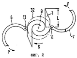
на фиг. 2 - схематичный вид сверху устройства по фиг. 1 с частично свернутым в рулон пакетом,
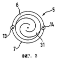
на фиг. 3 - схематичный вид сверху устройства по фиг. 1 с сомкнутой формой,
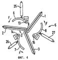
на фиг. 4 - схематичный вид сверху второго примера выполнения устройства с тремя пакетами,
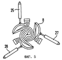
на фиг. 5 - схематичный вид сверху устройства по фиг. 4 с частично скрученными друг вокруг друга пакетами,
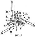
на фиг. 6 - вид сверху устройства по фиг. 4 с замкнутой формой,
на фиг. 7-12 - схематичные виды сверху третьего варианта выполнения устройства на различных технологических стадиях и
на фиг. 13-19 - схематичные виды сверху четвертого примера выполнения устройства.Other advantages and features of the device and method are explained in more detail on four examples of execution with reference to the accompanying drawings, which show:
in FIG. 1 is a schematic top view of a first embodiment of a device with one package,
in FIG. 2 is a schematic top view of the device of FIG. 1 with a packet partially rolled up,
in FIG. 3 is a schematic top view of the device of FIG. 1 closed
in FIG. 4 is a schematic top view of a second embodiment of a device with three packets,
in FIG. 5 is a schematic top view of the device of FIG. 4 with packages partially twisted around each other,
in FIG. 6 is a plan view of the device of FIG. 4 closed-loop
in FIG. 7-12 are schematic top views of a third embodiment of the device at various technological stages and
in FIG. 13-19 are schematic top views of a fourth embodiment of the device.
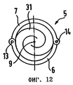
На фиг. 1-3 изображен первый пример выполнения устройства для изготовления элемента с сотовой структурой из одного пакета 1. Пакет 1 набран из множества по меньшей мере частично структурированных металлических листов, которые на фиг. 1-3 не изображены. По меньшей мере частично структурированные металлические листы образуют в готовом элементе с сотовой структурой множество каналов для прохождения текучей среды. Устройство включает форму 5, состоящую из двух профильных сегментов 6, 7. Каждый профильный сегмент 6, 7 может поворачиваться вокруг соответствующей оси 13, 14. Концы каждого профильного сегмента 6, 7 выполнены таким образом, что замкнутая форма образует почти непрерывную линию. В изображенном примере выполнения элемент 31 с сотовой структурой имеет круглое поперечное сечение. Два профильных элемента 6, 7 расположены диаметрально на огибающей 32. In FIG. 1-3, a first embodiment of a device for manufacturing an element with a honeycomb structure from one package 1 is shown. Package 1 is composed of a plurality of at least partially structured metal sheets, which in FIG. 1-3 are not shown. At least partially structured metal sheets form in the finished element with a honeycomb structure many channels for the passage of fluid. The device includes a
Пакет 1 помещают в открытую форму 5, в которой он удерживается не показанным скручивающим приспособлением. Скручивающее приспособление выполнено вильчатым и может поворачиваться вокруг оси 9, проходящей перпендикулярно плоскости чертежа. Направление поворота скручивающего приспособления вокруг оси 9 обозначено буквой S. На фиг. 2 видно, что пакет 1 частично свернут в рулон. Еще не свернутая в рулон часть пакета 1 имеет длину L, которая соответствует половине длины окружности огибающей 32. На этой стадии способа профильные сегменты 6, 7 могут быть повернуты в направлении стрелок F вокруг соответствующих осей 13, 14, смыкая таким образом форму 5. При этом профильные сегменты 6, 7 давят на еще не свернутый в рулон участок пакета 1 в направлении к его центру. The bag 1 is placed in an
На фиг. 4-6 показан второй пример выполнения устройства для изготовления элемента с сотовой структурой из трех пакетов 1, 2 и 3. Пакеты 1, 2 и 3 расположены симметрично вокруг оси 9. Для упрощения скручивающее приспособление, которое удерживает и проворачивает каждый пакет 1, 2 и 3 в направлении S, не показано. Скручивающее приспособление может быть выполнено, как уже было указано, в виде вильчатого приспособления. Форма 5 включает три профильных сегмента 6, 7 и 8. Каждый профильный сегмент 6, 7 и 8 выполнен в форме дуги окружности. Каждый профильный сегмент 6, 7 и 8 может поворачиваться вокруг соответствующей оси 13, 14 и 15 против направления поворота S скручивающего приспособления. Для поворота каждого профильного сегмента 6, 7 и 8 предусмотрен соответствующий приводной блок 25, 26 и 27. В качестве приводных блоков 25, 26 и 27 использованы поршневые блоки. Поршневые штоки 28, 29 и 30 соединены соответственно с профильными сегментами 6, 7 и 8. Соединение выполнено поворотным. Каждый приводной блок 25, 26, 27 выполнен стационарным. In FIG. Figures 4-6 show a second embodiment of a device for manufacturing an element with a honeycomb structure of three
В результате повышения давления в цилиндре поршневого блока 25, 26, 27 соответствующий поршневой шток 28, 29 и 30 выдвигается, благодаря чему каждый сегмент 6, 7 и 8 поворачивается вокруг соответствующей оси 13, 14 и 15, и форма 5 смыкается. Форма в сомкнутом состоянии показана на фиг. 6. As a result of the increase in pressure in the cylinder of the
На фиг. 7-12 представлен третий пример выполнения изобретения. Устройство для изготовления элемента с сотовой структурой из одного пакета 1 включает два профильных сегмента 6, 7, которые могут поворачиваться вокруг оси 13, соответственно 14. Каждый сегмент 6, 7 может перемещаться радиально в направлении к оси 9 скручивающего приспособления. На фиг. 7 изображено расположение пакета в открытой форме 5. После помещения пакета в форму и его захвата не показанным скручивающим приспособлением профильные сегменты 6, 7 перемещаются радиально внутрь в направлении стрелок R к пакету 1. Каждый профильный сегмент 6, 7 перемещается до упора в пакет одним из своих концов. На этом конце выполнена ось 13, соответственно 14 поворота. Конец профильного сегмента, прилегающий к пакету 1, образует контропору 10, 11. В процессе свертывания пакета 1 в рулон в направлении поворота S профильные сегменты 6, 7 перемещаются радиально наружу в направлении стрелок В, причем контропоры 10, 11 постоянно прилегают к пакету. Это, в частности, видно на фиг. 9, 10 и 11. После практически полного завершения процесса свертывания, осуществляемого скручивающим приспособлением, профильные сегменты 6, 7 поворачиваются вокруг их соответствующих осей 13, 14, и форма 5 замыкается. Фиг. 11 и 12 соответствуют фиг. 2 и 3, поэтому описание, относящиеся к этим последним чертежам, полностью относится и к данному примеру выполнения. In FIG. 7-12 show a third embodiment of the invention. A device for manufacturing an element with a honeycomb structure from one package 1 includes two
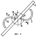
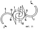
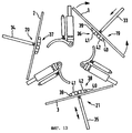
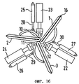
Для изготовления из множества по меньшей мере частично структурированных металлических листов элемента с сотовой структурой со множеством каналов для прохождения текучей среды, в частности корпуса-носителя каталитического нейтрализатора, содержащего три пакета 1, 2 и 3 металлических листов, причем эти три пакета 1, 2 и 3 сложены пополам по соответствующей линии 16, 17 и 18 сгиба в центральной зоне 4 элемента с сотовой структурой и в таком сложенном состоянии свернуты в рулон путем их скручивания друг вокруг друга в одном направлении вокруг центральной зоны 4, в которой находятся линии 16, 17 и 18 сгиба, предлагается устройство, изображенное на фиг. 13-19. Устройство включает три листогибочных блока 19, 20 и 21 для складывания пакетов пополам. Каждый листогибочный блок 19, 20 и 21 имеет гибочную оправку 33, 34 и 35. Гибочная оправка 33, 34 и 35 может совершать возвратно-поступательные движения. Каждый листогибочный блок 19, 20 и 21 содержит двухстворчатые затворы 36, 37 и 38. Затворы 36, 37 и 38 имеют по две створки 41, 42, поворачивающиеся вокруг соответствующих осей 39, 40. Поворот створок происходит против действия их прижимного усилия. Для складывания одного пакета 1, 2 и 3 последний располагают параллельно соответствующему затвору 36, 37 и 38. Симметрично между затворами 41, 42 расположена оправка 33. В результате приложения к пакету 1 усилия, создаваемого оправкой 33, и поворота створок 41, 42 пакет 1 складывается по линии 16 сгиба. Пакеты 1, 2 и 3 в сложенном состоянии показаны на фиг. 14. В процессе складывания пакетов 1, 2 и 3 их вводят в центральную зону 4 устройства. Пакеты 1, 2 и 3 располагают симметрично относительно оси 9. По окончании складывания пакетов производится извлечение оправок 33, 34, 35 из соответствующего пакета. На последующих фиг. 15-19 гибочные приспособления 19, 20 и 21 для упрощения не показаны. For manufacturing from a plurality of at least partially structured metal sheets an element with a honeycomb structure with a plurality of channels for the passage of a fluid, in particular a catalyst support housing comprising three
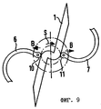
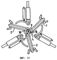
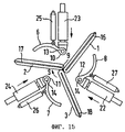
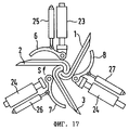
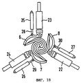
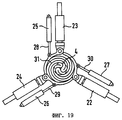
После захвата не показанным скручивающим приспособлением каждого пакета 1, 2 и 3 отдельные профильные сегменты 6, 7 и 8 с помощью поршневого блока 22, 23 и 24 перемещаются радиально внутрь по направлению к оси 9. Процесс перемещения происходит до тех пор, пока образованные на конце каждого профильного сегмента 6, 7 и 8 контропоры 10, 11 и 12 не упрутся в соответствующий пакет 1, 2 и 3, как это показано на фиг. 16. Процесс свертывания может быть начат, когда контропоры прилегают к пакету 1, 2 и 3. На фиг. 17 показаны отдельные пакеты 1, 2 и 3 в начальной стадии процесса их скручивания. Для смыкания формы 5 профильные сегменты 6, 7 и 8 могут поворачиваться соответственно вокруг оси 13, 14. Фиг. 18 и 19 соответствуют фиг. 5 и 6, поэтому описание, относящиеся к этим последним чертежам, полностью относится и к данному примеру выполнения. After the capture of each
Описанные в примерах выполнения элементы с сотовой структурой имеют круглое поперечное сечение. Согласно изобретению могут быть изготовлены также и элементы с некруглым поперечным сечением. При этом могут рассматриваться, например, элементы с сотовой структурой, которые имеют поперечное сечение в виде эллипса, части круга или эпитрохоиды. The honeycomb elements described in the exemplary embodiments have a circular cross section. According to the invention, elements with a non-circular cross section can also be manufactured. This can be considered, for example, elements with a honeycomb structure, which have a cross section in the form of an ellipse, part of a circle or epitrochoid.
Claims (21)
Applications Claiming Priority (2)
| Application Number | Priority Date | Filing Date | Title |
|---|---|---|---|
| DE19521685A DE19521685C2 (en) | 1995-06-14 | 1995-06-14 | Method and device for manufacturing a honeycomb body |
| DE19521685.7 | 1995-06-14 |
Publications (2)
| Publication Number | Publication Date |
|---|---|
| RU98101118A RU98101118A (en) | 2000-01-10 |
| RU2154528C2 true RU2154528C2 (en) | 2000-08-20 |
Family
ID=7764393
Family Applications (1)
| Application Number | Title | Priority Date | Filing Date |
|---|---|---|---|
| RU98101118/12A RU2154528C2 (en) | 1995-06-14 | 1996-05-15 | Device and method for manufacture of member with cellular structure, particularly, carrier-body of catalytic neutralizer |
Country Status (14)
| Country | Link |
|---|---|
| EP (1) | EP0831969B1 (en) |
| JP (1) | JP3853365B2 (en) |
| KR (1) | KR100396963B1 (en) |
| CN (1) | CN1078101C (en) |
| AU (1) | AU5818796A (en) |
| BR (1) | BR9608354A (en) |
| DE (2) | DE19521685C2 (en) |
| ES (1) | ES2137707T3 (en) |
| IN (1) | IN191301B (en) |
| MX (1) | MX9710014A (en) |
| MY (1) | MY116654A (en) |
| RU (1) | RU2154528C2 (en) |
| TW (1) | TW327144B (en) |
| WO (1) | WO1997000135A1 (en) |
Families Citing this family (20)
| Publication number | Priority date | Publication date | Assignee | Title |
|---|---|---|---|---|
| DE19704521A1 (en) | 1997-02-06 | 1998-08-13 | Emitec Emissionstechnologie | Method and device for producing a honeycomb body |
| GB2325424B (en) * | 1997-05-20 | 2001-01-24 | Emitec Emissionstechnologie | Production of a honeycomb body of twisted sheet layers |
| DE19755703B4 (en) * | 1997-12-15 | 2008-03-13 | Emitec Gesellschaft Für Emissionstechnologie Mbh | Catalyst support arrangement for installation close to the engine |
| KR100517786B1 (en) | 1997-09-03 | 2005-09-30 | 에미텍 게젤샤프트 퓌어 에미시온스테크놀로기 엠베하 | Catalyst support assembly to be mounted in an engine compartment |
| DE19817787C2 (en) | 1998-04-21 | 2000-04-13 | Emitec Emissionstechnologie | Method and device for producing a metallic honeycomb body |
| DE19825018A1 (en) | 1998-06-04 | 1999-12-09 | Emitec Emissionstechnologie | Method and laminated core for producing a honeycomb body with a plurality of channels that are permeable to a fluid |
| DE19912871A1 (en) | 1999-03-22 | 2000-09-28 | Emitec Emissionstechnologie | Method and device for producing a metallic honeycomb body |
| DE10226282A1 (en) | 2002-06-13 | 2003-12-24 | Emitec Emissionstechnologie | Non-cylindrical catalyst carrier body and tool and method for its production |
| DE10329002A1 (en) | 2003-06-27 | 2005-01-20 | Emitec Gesellschaft Für Emissionstechnologie Mbh | Structure of a metallic honeycomb structure and method for its production |
| DE102005038572A1 (en) * | 2005-08-12 | 2007-02-15 | Emitec Gesellschaft Für Emissionstechnologie Mbh | Apparatus and method for producing metallic honeycomb bodies having at least one mold segment |
| CN101251036B (en) * | 2007-08-29 | 2010-06-09 | 温州市亿达环保技术有限公司 | Apparatus for preparing S type metallic honeycomb |
| DE102009035612A1 (en) | 2009-07-31 | 2011-02-03 | Emitec Gesellschaft Für Emissionstechnologie Mbh | Method for soldering a honeycomb body for vehicle with a combustion engine, comprises inserting the honeycomb body into a fixing means, soldering the honeycomb body and removing the fixing means from the honeycomb body |
| JP5760152B2 (en) * | 2011-11-01 | 2015-08-05 | ビーエーエスエフ コーポレーション | System and method for manufacturing a honeycomb body |
| CN102784852B (en) * | 2012-02-14 | 2014-07-23 | 无锡敏功科技有限公司 | Fabricating device for S-shaped metal honeycomb supporter |
| CN102553980A (en) * | 2012-02-24 | 2012-07-11 | 丁胜康 | Rolling device for double-S honeycomb metal carriers |
| CN102699164A (en) * | 2012-05-16 | 2012-10-03 | 丁胜康 | Metal honeycomb carrier rolling device |
| CN102728677B (en) * | 2012-06-19 | 2016-04-13 | 台州欧信环保净化器有限公司 | A kind of producing device of S type metal beehive carrier |
| CN104826903B (en) * | 2015-05-11 | 2016-03-23 | 季金菊 | The forming method of two S type honeycomb substrate and shaped device thereof |
| DE102016210235A1 (en) | 2016-06-09 | 2017-12-28 | Continental Automotive Gmbh | Process for producing a honeycomb structure |
| CN109019149B (en) * | 2018-06-13 | 2020-05-15 | 北京安达泰克科技有限公司 | Winding equipment of metal honeycomb carrier |
Family Cites Families (9)
| Publication number | Priority date | Publication date | Assignee | Title |
|---|---|---|---|---|
| DE3760479D1 (en) * | 1986-05-12 | 1989-09-28 | Interatom | Honeycomb body, particularly a catalyst carrier, provided with opposedly folded metal sheet layers, and its manufacturing process |
| DE3743724A1 (en) * | 1987-12-23 | 1989-07-13 | Hoerauf Maschinenfabrik Gmbh & | LETTER FOLDER COVER |
| DE3743723C1 (en) * | 1987-12-23 | 1989-04-20 | Sueddeutsche Kuehler Behr | Method and device for producing a support body for a catalytic reactor |
| WO1990003220A1 (en) * | 1988-09-22 | 1990-04-05 | Emitec Gesellschaft Für Emissionstechnologie Mbh | Honeycomb structure, in particular catalyst support, composed of a plurality of interlaced bundles of sheet metal |
| CN1021023C (en) * | 1988-09-22 | 1993-06-02 | 埃米特放射技术股份有限公司 | Honeycomb made of multiwrapping stacking sheets, especially use in carrier of catalyst |
| CA2083742A1 (en) * | 1992-02-19 | 1993-08-20 | David T. Sheller | Core element for catalytic converter |
| EP0569109A1 (en) * | 1992-05-04 | 1993-11-10 | W.R. Grace & Co.-Conn. | Core element for catalytic converter |
| DE4221763A1 (en) * | 1992-07-02 | 1994-01-05 | Schwaebische Huettenwerke Gmbh | Method of making a catalyst |
| ES2086948T3 (en) * | 1992-07-14 | 1996-07-01 | Emitec Emissionstechnologie | METALLIC ALVEOLAR BODY COMPOSED OF INTERLOCKING PLATE LAYERS, AND PROCEDURE FOR ITS MANUFACTURE. |
-
1995
- 1995-06-14 DE DE19521685A patent/DE19521685C2/en not_active Expired - Fee Related
-
1996
- 1996-05-06 IN IN828CA1996 patent/IN191301B/en unknown
- 1996-05-09 TW TW085105507A patent/TW327144B/en not_active IP Right Cessation
- 1996-05-15 RU RU98101118/12A patent/RU2154528C2/en not_active IP Right Cessation
- 1996-05-15 EP EP96919776A patent/EP0831969B1/en not_active Expired - Lifetime
- 1996-05-15 WO PCT/EP1996/002094 patent/WO1997000135A1/en active IP Right Grant
- 1996-05-15 BR BR9608354A patent/BR9608354A/en not_active IP Right Cessation
- 1996-05-15 AU AU58187/96A patent/AU5818796A/en not_active Abandoned
- 1996-05-15 CN CN96194765A patent/CN1078101C/en not_active Expired - Fee Related
- 1996-05-15 DE DE59602954T patent/DE59602954D1/en not_active Expired - Lifetime
- 1996-05-15 JP JP50254297A patent/JP3853365B2/en not_active Expired - Lifetime
- 1996-05-15 ES ES96919776T patent/ES2137707T3/en not_active Expired - Lifetime
- 1996-05-15 KR KR1019970709323A patent/KR100396963B1/en not_active IP Right Cessation
- 1996-06-12 MY MYPI96002361A patent/MY116654A/en unknown
-
1997
- 1997-12-10 MX MX9710014A patent/MX9710014A/en unknown
Also Published As
| Publication number | Publication date |
|---|---|
| CN1187784A (en) | 1998-07-15 |
| IN191301B (en) | 2003-11-15 |
| KR19990022854A (en) | 1999-03-25 |
| DE59602954D1 (en) | 1999-10-07 |
| MY116654A (en) | 2004-03-31 |
| ES2137707T3 (en) | 1999-12-16 |
| JP3853365B2 (en) | 2006-12-06 |
| AU5818796A (en) | 1997-01-15 |
| CN1078101C (en) | 2002-01-23 |
| JPH11508814A (en) | 1999-08-03 |
| TW327144B (en) | 1998-02-21 |
| KR100396963B1 (en) | 2003-10-17 |
| BR9608354A (en) | 1998-07-28 |
| DE19521685A1 (en) | 1996-12-19 |
| WO1997000135A1 (en) | 1997-01-03 |
| MX9710014A (en) | 1998-07-31 |
| EP0831969B1 (en) | 1999-09-01 |
| DE19521685C2 (en) | 1998-04-16 |
| EP0831969A1 (en) | 1998-04-01 |
Similar Documents
| Publication | Publication Date | Title |
|---|---|---|
| RU2154528C2 (en) | Device and method for manufacture of member with cellular structure, particularly, carrier-body of catalytic neutralizer | |
| RU2233207C2 (en) | Method for making honeycomb metallic member and apparatus for performing the same | |
| RU98101118A (en) | DEVICE AND METHOD FOR PRODUCING AN ELEMENT WITH CELL STRUCTURE, IN PARTICULAR OF THE HOUSING CARRIER OF THE CATALYTIC NEUTRALIZER | |
| US7293350B2 (en) | Coil forming apparatus of forming coils of a stator of a rotary electric machine | |
| US5846177A (en) | Folding mechanism cylinder having an adjustable diameter | |
| US6049961A (en) | Process for producing a honeycomb body, especially a catalyst carrier body | |
| US9649768B2 (en) | Formation and rotational apparatus and method for cylindrical workpieces | |
| EP1912752B1 (en) | Process and device for producing metallic honeycomb bodies with at least one shaped segment | |
| JP2957153B2 (en) | Pipe end forming method and apparatus | |
| US6311395B1 (en) | Apparatus and method for producing a honeycomb body | |
| JP3930906B2 (en) | Apparatus and process for manufacturing a honeycomb body | |
| RU2153934C2 (en) | Device and method for manufacturing member with cellular structure from metals sheet coiled into coil | |
| US6851176B2 (en) | Method for the manufacture of bundles of metal sheets of annular shape | |
| RU2184007C2 (en) | Method and apparatus for making honeycomb member | |
| DE2511855B2 (en) | Flywheel with several rings made of anisotropic material | |
| US5772097A (en) | Binding device | |
| PL181040B1 (en) | Method of and apparatus for crimping a portion of cylindrical hollow body and circumferentially turning in the edge of that portion | |
| CN109494397A (en) | A kind of hot pressing mechanism and secondly encapsulation method of soft-package battery | |
| DE19704689A1 (en) | Honeycomb body with a free cross-sectional area inside, especially for small engines | |
| US4216892A (en) | Device for manufacturing stator cores | |
| JPH0798523B2 (en) | Cylindrical body end face wrapping device | |
| SU1286315A1 (en) | Apparatus for manufacturing shells |
Legal Events
| Date | Code | Title | Description |
|---|---|---|---|
| MM4A | The patent is invalid due to non-payment of fees |
Effective date: 20150516 |