JP3853365B2 - Apparatus and process for manufacturing a honeycomb body - Google Patents
Apparatus and process for manufacturing a honeycomb body Download PDFInfo
- Publication number
- JP3853365B2 JP3853365B2 JP50254297A JP50254297A JP3853365B2 JP 3853365 B2 JP3853365 B2 JP 3853365B2 JP 50254297 A JP50254297 A JP 50254297A JP 50254297 A JP50254297 A JP 50254297A JP 3853365 B2 JP3853365 B2 JP 3853365B2
- Authority
- JP
- Japan
- Prior art keywords
- former
- stack
- honeycomb body
- axis
- stacks
- Prior art date
- Legal status (The legal status is an assumption and is not a legal conclusion. Google has not performed a legal analysis and makes no representation as to the accuracy of the status listed.)
- Expired - Lifetime
Links
- 238000000034 method Methods 0.000 title claims description 20
- 238000004519 manufacturing process Methods 0.000 title claims description 19
- 238000004804 winding Methods 0.000 claims description 41
- 239000002184 metal Substances 0.000 claims description 29
- 239000012530 fluid Substances 0.000 claims description 11
- 230000003197 catalytic effect Effects 0.000 claims description 10
- 230000006835 compression Effects 0.000 claims description 2
- 238000007906 compression Methods 0.000 claims description 2
- 230000003247 decreasing effect Effects 0.000 claims description 2
- 238000005452 bending Methods 0.000 description 7
- 230000001419 dependent effect Effects 0.000 description 2
- 238000003825 pressing Methods 0.000 description 2
- 230000002411 adverse Effects 0.000 description 1
- 230000005540 biological transmission Effects 0.000 description 1
- 230000000694 effects Effects 0.000 description 1
- 239000003344 environmental pollutant Substances 0.000 description 1
- 230000001771 impaired effect Effects 0.000 description 1
- 231100000719 pollutant Toxicity 0.000 description 1
- 239000007858 starting material Substances 0.000 description 1
- 230000001960 triggered effect Effects 0.000 description 1
Images


Classifications
-
- B01J35/56—
-
- F—MECHANICAL ENGINEERING; LIGHTING; HEATING; WEAPONS; BLASTING
- F01—MACHINES OR ENGINES IN GENERAL; ENGINE PLANTS IN GENERAL; STEAM ENGINES
- F01N—GAS-FLOW SILENCERS OR EXHAUST APPARATUS FOR MACHINES OR ENGINES IN GENERAL; GAS-FLOW SILENCERS OR EXHAUST APPARATUS FOR INTERNAL COMBUSTION ENGINES
- F01N3/00—Exhaust or silencing apparatus having means for purifying, rendering innocuous, or otherwise treating exhaust
- F01N3/08—Exhaust or silencing apparatus having means for purifying, rendering innocuous, or otherwise treating exhaust for rendering innocuous
- F01N3/10—Exhaust or silencing apparatus having means for purifying, rendering innocuous, or otherwise treating exhaust for rendering innocuous by thermal or catalytic conversion of noxious components of exhaust
- F01N3/24—Exhaust or silencing apparatus having means for purifying, rendering innocuous, or otherwise treating exhaust for rendering innocuous by thermal or catalytic conversion of noxious components of exhaust characterised by constructional aspects of converting apparatus
- F01N3/28—Construction of catalytic reactors
- F01N3/2803—Construction of catalytic reactors characterised by structure, by material or by manufacturing of catalyst support
- F01N3/2807—Metal other than sintered metal
- F01N3/281—Metallic honeycomb monoliths made of stacked or rolled sheets, foils or plates
-
- B—PERFORMING OPERATIONS; TRANSPORTING
- B21—MECHANICAL METAL-WORKING WITHOUT ESSENTIALLY REMOVING MATERIAL; PUNCHING METAL
- B21D—WORKING OR PROCESSING OF SHEET METAL OR METAL TUBES, RODS OR PROFILES WITHOUT ESSENTIALLY REMOVING MATERIAL; PUNCHING METAL
- B21D53/00—Making other particular articles
- B21D53/02—Making other particular articles heat exchangers or parts thereof, e.g. radiators, condensers fins, headers
- B21D53/027—Making other particular articles heat exchangers or parts thereof, e.g. radiators, condensers fins, headers by helically or spirally winding elongated elements
-
- F—MECHANICAL ENGINEERING; LIGHTING; HEATING; WEAPONS; BLASTING
- F01—MACHINES OR ENGINES IN GENERAL; ENGINE PLANTS IN GENERAL; STEAM ENGINES
- F01N—GAS-FLOW SILENCERS OR EXHAUST APPARATUS FOR MACHINES OR ENGINES IN GENERAL; GAS-FLOW SILENCERS OR EXHAUST APPARATUS FOR INTERNAL COMBUSTION ENGINES
- F01N3/00—Exhaust or silencing apparatus having means for purifying, rendering innocuous, or otherwise treating exhaust
- F01N3/08—Exhaust or silencing apparatus having means for purifying, rendering innocuous, or otherwise treating exhaust for rendering innocuous
- F01N3/10—Exhaust or silencing apparatus having means for purifying, rendering innocuous, or otherwise treating exhaust for rendering innocuous by thermal or catalytic conversion of noxious components of exhaust
- F01N3/24—Exhaust or silencing apparatus having means for purifying, rendering innocuous, or otherwise treating exhaust for rendering innocuous by thermal or catalytic conversion of noxious components of exhaust characterised by constructional aspects of converting apparatus
- F01N3/28—Construction of catalytic reactors
-
- F—MECHANICAL ENGINEERING; LIGHTING; HEATING; WEAPONS; BLASTING
- F01—MACHINES OR ENGINES IN GENERAL; ENGINE PLANTS IN GENERAL; STEAM ENGINES
- F01N—GAS-FLOW SILENCERS OR EXHAUST APPARATUS FOR MACHINES OR ENGINES IN GENERAL; GAS-FLOW SILENCERS OR EXHAUST APPARATUS FOR INTERNAL COMBUSTION ENGINES
- F01N2330/00—Structure of catalyst support or particle filter
- F01N2330/02—Metallic plates or honeycombs, e.g. superposed or rolled-up corrugated or otherwise deformed sheet metal
- F01N2330/04—Methods of manufacturing
Description
この発明は、流体浸透性の複数の通路を有するハニカム本体、特定的には触媒コンバータキャリア本体を製造するための装置およびプロセスに関する。
触媒コンバータキャリア本体は、特に自動車の排気ガス中の汚染物質を除去するために用いられる。このような触媒コンバータキャリア本体は金属のハニカム本体に関わり得る。ハニカム本体は、少なくとも部分的に構造物である複数のメタルシートを備える積重ねを含む。積重ねはそれ自身の周りおよび中央領域の周りで反対方向に捩じられる。ハニカム本体のこのような設計形態は、たとえば米国特許第4 923 109から公知である。
WO 90/03220には、自動車用の金属の触媒コンバータキャリア本体が開示されており、これは少なくとも部分的に構造物である金属シートを含む。この触媒コンバータキャリア本体は、メタルシートの少なくとも3つの積重ねを含み、少なくとも3つのこれらの積重ねの各々は、ハニカム本体の中央領域における、それぞれに関連した折り線の周りで折り曲げられ、折り曲げられた状態で互いの周りに、かつ折り線を有する中央領域の周りに同じ方向に捩じられる。
このような触媒コンバータキャリア本体を製造するための装置は公知であり、この装置は、軸の周りで回転可能であり、かつ各積重ねを係合するフォーク状の巻付け装置と、フォーマを成すように閉じるフォーマセグメントとを含む。閉じたフォーマの内形は、巻付けられた状態のハニカム本体の外形に対応する。ハニカム本体は円筒形に製造されることが最も多い。積重ねがそれらの周りおよび中央領域の周りに確実に巻付けられるようにするために、フォーク状の捩じり装置の回転運動時に、フォーマセグメントは、積重ねがフォーマセグメントのエッジを圧迫し、エッジが支持手段を形成するような方法で、積重ねの方に移動する。
製造工程が終わる頃には、フォーマは完全に閉じられ、このようにして最終的な形状をハニカム本体に与える。
公知の装置は2つのフォーマセグメントを有し、これらのセグメントは直線において互いに向かって、かつ互いから離れるように移動可能である。閉じ動作時には、フォーマセグメントのうち少なくとも一方が、依然として捩じられるべき積重ねの部分の移動方向の反対の方向に移動するおそれがある。もしフォーマセグメントが積重ねのその部分に遭遇すれば、積重ねが不所望にも変形するおそれがある。このような変形により、結果として個々のメタルシートが部分的に歪んでしまう。この結果、完成したハニカム本体の構造が悪影響を受ける。このため、一方ではハニカム本体の強度が損なわれ、他方では通路の断面が局部的に変形するという問題が生ずる。
以上のことを基礎的な出発点として、この発明は、製造工程の間に積重ねまたは個々のメタルシートが変形するおそれのない、ハニカム本体を製造するための公知の装置を開発するという課題に基づく。この発明はさらに、個々の積重ねの変形を避ける、ハニカム本体を製造するためのプロセスを提供する。
この発明によると、上述の問題は請求項1に記載される特徴を有する装置によって解決される。装置を有利に開発することが従属項2から12の主題である。この発明に従った、ハニカム本体を製造するためのプロセスは請求項13および14に記載される。プロセスを有利に発展させることが従属項15の主題である。
この発明に従った装置であって、流体浸透性の複数の通路を形成する、少なくとも部分的に構造物である複数のメタルシートを含む少なくとも1つの積重ねからハニカム本体を製造するためのものは、少なくとも2つのフォーマセグメントを有するフォーマを有する。各フォーマセグメントは、巻付け装置の軸にそれぞれ平行に延びるそれぞれの旋回軸の周りで、巻付け装置の回転方向と反対の方向に旋回可能である。各フォーマセグメントが巻付け装置の回転方向と反対の方向に旋回運動することにより、フォーマを閉じたときに、シートメタルの1つまたはそれ以上の積重ねが確実にひっくり返ら(upset)ないないようになる。好ましくは、2つより多い積重ねを扱うときには、装置は積重ねの数に対応する数のフォーマセグメントを有し、これらのフォーマセグメントは巻付け装置の回転方向とは反対の方向に旋回可能である。好ましくは、フォーマセグメントの旋回軸は、完成したハニカム本体の周りで、エンベロープ上に互いに対して等しい距離をおいて配置される。
ハニカム本体を製造するための公知の装置の構造によると、ハニカム本体の積重ねのメタルシートは大きな負荷を受ける。メタルシート上の負荷はとりわけ、支持手段が、加えられる力の中心に対して間隔をおいておかれることが原因である。支持手段と、シートメタルの積重ねと、加えられる力の中心とを含むシステムは、一端でクランプされた重ね板ばねに匹敵する。この種の重ね板ばねの場合にもまた、積重ねの個々の層の間に摩擦が生ずる。これらの摩擦効果により、巻付け動作中に加えられるエネルギが増加する。さらに、各積重ねのうちまだ巻付けられていない部分が歪むため、積重ねにスクイージング(squeezing)または押圧動作を施す必要がある。
装置と、有利に発展させた方法とは下記の基礎的な概念にかかわる。すなわち流体浸透性の複数の通路を有するハニカム本体、特定的には触媒コンバータキャリア本体の製造は、支持手段が、巻付けられた積重ねを直接圧迫するならばより望ましいということである。各積重ねのうちまだ巻付けられていない部分は固定されていない。このため、積重ねのうちまだ巻付けられていない部分上には、先行技術の場合のように負荷は加えられない。したがって、積重ねのうちまだ巻付けられていない部分上に曲げ負荷は加えられない。
この基礎的な概念は、流体浸透性の複数の通路を有するハニカム本体、特定的には触媒コンバータを製造するための装置において、請求項4に従って実現され、このハニカム本体は少なくとも部分的に構造物である複数のメタルシートの積重ねを含み、この装置は、軸周りに回転可能でありかつ積重ねを係合するフォーク状の巻付け装置と、包囲するフォーマセグメントとを有し、この包囲するフォーマセグメントにはフォーマセグメントが設けられ、旋回軸がそれぞれの端部に配置され、このそれぞれの端部がフォーマセグメントの支持手段を形成し、各支持手段は軸の方に、かつ軸から離れるように移動可能である。この装置において、支持手段は、巻付け動作時には常に積重ねを圧迫する。巻付け工程の間、巻付けられた積重ねの半径方向の厚みが増加する。この工程を考慮するよう、支持手段は巻付け装置の軸に向かって、かつそこから離れるように移動可能である。支持手段は一定の圧力で積重ねを圧迫し得る。
少なくとも部分的に構造物である複数のメタルシートを含む少なくとも3つの積重ねからハニカム本体が形成され、かつ積重ねが互いの周りに同時に捩じられる場合には、フォーマのフォーマセグメントの数が積重ねの数と一致する装置が提案される。各フォーマセグメントは旋回軸の周りで旋回可能であり、この旋回軸は軸に平行に延び、かつそれぞれの支持手段を形成する端部に配置される。フォーマセグメントは巻付け装置の回転方向とは反対の方向に旋回可能である。各支持手段は巻付け装置の軸の方に、かつそこから離れるよう移動可能である。WO 90/03220に記載されているようなハニカム本体は、このような装置によって製造することができる。
さらなる有利な概念によると、中心に対して半径方向に延びるガイド溝を備えたベースプレートを有する装置の開発が提案されている。旋回軸を形成するピンが各ガイド溝の中に摺動可能に導かれる。各ガイド溝は多角形の断面を有する。ガイド溝の好ましい形状は、T形またはダブテール形の断面を有するものである。ピンは、ガイド溝の中に係合する対応するヘッドを有する。ガイド溝は一体的なベースプレートに設けられる必要はない。ガイド溝はまた、適当な形態を有する複数のプレートから作られてもよい。
支持手段の、軸に向かう、かつ軸から離れる移動は好ましくは電動機によって行なわれる。この目的のためにはステッピングモータが適切である。なぜならこれは、既に巻付けられている積重ねの支持手段の移動を精密に調節することができるからである。また、電動機ドライブと支持手段との間に、適切な伝動装置が設けられてもよい。他の可能性を考えることも可能であり、たとえば歯付きラックであって、一端において支持手段に接続され、電動機ドライブの、対応するギアと係合可能であるものでもよい。
好ましく開発された装置は、各支持手段がピストンシリンダ装置に接続されたものである。ピストンシリンダ装置は液圧または空圧作用により動作し得る。この点では、公知の規格ピストンシリンダ装置を用いることもできる。
さらに有利に開発した発明によると、旋回軸がばね力に抗して中心軸から離れるように移動することが提案される。このようなばね力が引張ばねか、圧縮ばねか、このようなばねの組合せによって生じ得る。好ましくは、それによって支持手段が、捩じられた積重ねを圧迫するばね力は、調節可能である。これにより、装置がハニカム本体の形および出発材料に適合できるようになる。好ましくは、ばね力は逓減特性を有する。これは、曲げ半径が大きいため、それにより支持手段が積重ねを圧迫する力が、曲げられた積重ねのコアにおけるよりも小さくなり得るということの考慮に基づく。さらに、ばねを用いることには、それらが、安全で信頼性高く動作する規格コンポーネントにかかわるという利点がある。
フォーマを閉じるために、各フォーマセグメントは、それぞれの旋回軸の周りで、対応するフォーマセグメントを旋回する駆動装置に接続されている。この駆動装置は液圧または空圧作用によって動作するピストンシリンダ装置であってもよい。
次に、少なくとも部分的に構造物である複数のメタルシートから、流体浸透性の複数の通路を有するハニカム本体を製造するためのプロセスを説明する。このプロセスにおいて、少なくとも部分的に構造物である多数のメタルシートを含む、シートメタルの積重ねが積重ねられる。この積重ねは開いたフォーマの中に導入される。積重ねおよびフォーマの中央領域において、積重ねは巻付け装置によって保持される。巻付け装置はフォーク状の形態のものであってもよい。積重ねは巻付け装置によって巻付けられる。フォーマセグメントが、巻付け装置の回転方向とは反対の方向に旋回運動すると、フォーマが閉じる。予め定められた程度の巻付けが行なわれるとフォーマは閉じ得る。積重ねはそれ自身の周りに完全に巻付けられなくてもよい。積重ねのうちまだ巻付けられていない部分が、フォーマセグメントの外周方向の長さ以下になると、フォーマの閉じ動作を開始することができる。そのとき、既に閉じ動作が開始していれば、各セグメントが巻付け動作を補助する。なぜなら、セグメントが閉じる際に、まだ巻付けられていない部分が軸の方に促されるからである。このプロセスにより、EP 0 245 737から公知であるハニカム本体が製造される。このようなハニカム本体はS−Catの名称で当業者には知らている。
たとえばWO 89/03220に記載されているような、少なくとも部分的に構造物である複数のメタルシートから、流体浸透性の複数の通路を有するハニカム本体を製造するために、少なくとも部分的に構造物である多数のメタルシートから多数の積重ねを積重ねることが提案されている。各積重ねはそれぞれの折り線の周りで折り曲げられる。各積重ねは開いたフォーマの中に導入され、フォーマの中央領域において、巻付け装置によって保持される。
さらに有利に開発したプロセスによると、巻付け装置が積重ねと係合した後に、それぞれの支持手段を中央領域において積重ねの両側に配置し、支持手段を対向関係に位置づけて積重ねを圧迫するようにすることが提案されている。その後、積重ねは反対方向にそれ自身の周りに巻付けられる。巻付け動作時に、各支持手段は中央領域から、半径方向に離れるよう移動し、支持手段は常に積重ねを圧迫する。巻付け動作が終了すると、フォーマセグメントがそれらのそれぞれの旋回軸の周りで旋回し、それによりフォーマが閉じる。
この発明に従った装置およびプロセスのさらなる利点および特徴は、図面に示される4つの実施例を参照して説明され、図面において、
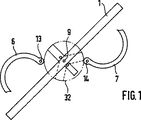
図1は、積重ねを有する装置の第1の実施例の概略平面図であり、
図2は、積重ねが部分的に巻付けられた、図1に示される装置の概略平面図であり、
図3は、閉じたフォーマを有する、図1の装置の概略平面図であり、
図4は、3つの積重ねを有する装置の第2の実施例の概略平面図であり、
図5は、積重ねが互いの周りに部分的に巻付けられた、図4の装置の概略平面図であり、
図6は、フォーマが閉じた、図4の装置の平面図であり、
図7から図12は、異なった動作段階にある、装置の第3の実施例の概略平面図であり、
図13から図19は、装置の第4の実施例の概略平面図である。
図1から図3は、積重ね1からハニカム本体を製造するための装置の第1の実施例を示す。積重ね1は、少なくとも部分的に構造物である複数のメタルシートを含み、これらのメタルシートは図1から図3には示されていない。完成したハニカム本体において、少なくとも部分的に構造物であるメタルシートにより、流体浸透性の複数の通路が形成される。装置はフォーマ5を含み、これは2つのフォーマセグメント6および7を備える。各フォーマセグメント6および7はそれぞれの旋回軸13および14周りで旋回可能である。各フォーマセグメント6および7の端部は、閉じたフォーマが、ほぼ連続した線を成すような形態である。示した実施例において、ハニカム本体31は円形の断面を有する。2つのフォーマセグメント6および7は、エンベロープ32上に対向して形成される。
積重ね1は開いたフォーマ5の中に導入され、かつそこに巻付け装置(図示せず)によって保持される。巻付け装置はフォーク状の形態であり、図の面に対して垂直である軸9の周りで回転可能である。軸9の周りを巻付け装置が回転する方向はSで示される。積重ねが部分的に捩じられていることは図2からわかるであろう。積重ね1のうちまだ巻付けられていない部分は長さLであり、これはエンベロープ32の外周の半分に対応する。このプロセス段階において、フォーマセグメント6および7はそれぞれの旋回軸13および14周りを矢印Fで示される方向に旋回することができ、それによりフォーマ5を閉じるようにする。それが行なわれると、フォーマセグメント6および7は、積重ね1のうちまだ巻付けられていない部分を積重ねのコアに対して押圧する。
図4から図6は、3つの積重ね1、2および3を含むハニカム本体を製造するための装置の第2の実施例を示す。積重ね1、2および3は軸9の周りで対称に配置される。各積重ね1、2および3を保持し、かつそれを回転方向Sに回転する巻付け装置は、図面を明瞭にするために示されていない。先に述べたとおり、巻付け装置はフォーク状の装置にかかわり得る。フォーマ5は3つのフォーマセグメント6、7および8を含む。各フォーマセグメント6、7および8は円のセクタの形である。各フォーマセグメント6、7および8は、巻付け装置の回転方向Sとは反対の方向にそれぞれの軸13、14および15の周りで旋回可能である。それぞれの駆動装置25、26および27は、各フォーマセグメント6、7および8を旋回運動させるために設けられる。駆動装置25、26および27の各々はピストンシリンダ装置を有する。ピストンロッド28、29および30がフォーマセグメント6、7および8にそれぞれ接続される。この接続部は旋回可能である。各駆動装置25、26および27は定置に置かれる。
ピストンシリンダ装置25、26および27内に圧力を適度に発生することにより、それぞれのピストンロッド28、29および30が延び、それにより各セグメント6、7および8がそれぞれの旋回軸13、14および15の周りで旋回し、フォーマが閉じる。閉じた状態のフォーマが図6に示される。
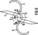
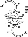
次に、図7から図12に示される第3の実施例を説明する。積重ね1からハニカム本体を製造するための装置は2つのフォーマセグメント6および7を有し、これらの各々は旋回軸13および14の周りで旋回可能である。各セグメント6および7は巻付け装置の軸9に対して半径方向に移動可能である。図7は、開いたフォーマ5における積重ねの配置を示す。積重ねがフォーマに配置され、巻付け装置(図示せず)に係合された後、フォーマセグメント6および7は矢印Rの方向に、半径方向に内向きに積重ね1に向かって移動する。各フォーマセグメント6および7はその一端で積重ねを圧迫するようにされる。それぞれの旋回軸13および14はそれぞれ、その端部に設けられる。積重ね1を圧迫するフォーマセグメントの端部により支持手段10および11が形成される。回転方向Sに積重ね1を捩じる動作の間、フォーマセグメント6および7は方向Bに半径方向に外向きに移動し、この場合支持手段10および11は常に積重ねを圧迫する。これは特に、図9、10および11において明らかに示される。巻付け動作が実質的に終了した後、フォーマセグメント6および7がそれらのそれぞれの旋回軸13および14の周りで旋回し、フォーマが閉じる。図11および図12は図2および図3に対応する。それらの全内容に関して、これらの図の説明が参照される。
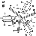
流体浸透性の複数の通路を有するハニカム本体、特定的には触媒コンバータキャリア本体であって、メタルシートの3つの積重ね1、2および3を含み、これら3つの積重ね1、2および3の各々が、ハニカム本体の中央領域におけるそれぞれの折り線16、17および18の周りで折り曲げられ、さらに、互いの周りに、かつ中央領域4の周りに折り線16、17および18によって同じ方向に折り曲げられた状態で捩じられたものを、少なくとも部分的に構造物である複数のメタルシートから製造するために、図13から19に示される装置が提案される。装置は3つの折り曲げ装置19、20および21を含む。折り曲げ装置19、20および21の各々は折り曲げ棒33、34および35を有する。折り曲げ棒33、34および35は直線状に往復運動することができる。折り曲げ装置19、20および21の各々は、2つの部品のエントリロック装置36、37および38を有する。ロック装置36、37および38の各々は2つのゲート41および42を有し、これらは軸39および40の周りで旋回可能である。旋回は力に抗して引き起こされる。積重ね1、2および3を折り曲げるために、積重ねはそれぞれロック装置36、37および38に平行に配置される。棒33はロック装置ゲート41および42間で対称に配置される。積重ね1は、ゲート41および42が旋回可能であることにより、かつ積重ね1に対して棒33の力を加えることにより、折り線16の周りで折り曲げられる。折り曲げられた状態が図14に示される。折り曲げ動作により、積重ね1、2および3が装置の中央領域に導入される。積重ね1、2および3は軸9に対して対称に配置される。折り曲げ動作が行なわれた後、棒33、34および35が、それぞれの積重ねから引き出される。図を明瞭にするために、折り曲げ装置19、20および21は以下の図15から図19には示していない。
巻付け装置(図示せず)は各積重ね1、2および3を係合している。個々のフォーマセグメント6、7および8はピストンシリンダ装置22、23および24によって軸9の方に半径方向に内向きに移動される。移動動作は、図16に示されるように、各フォーマセグメント6、7および8の端部に設けられた支持手段10、11および12がそれぞれの積重ね1、2および3を圧迫するまで続く。支持手段が積重ね1、2および3を圧迫すると、巻付け動作が開始し得る。図17は、個々の積重ね1、2および3の巻付けを示す。フォーマセグメント6、7および8の各々は、フォーマ5を閉じるようそれぞれの旋回軸13および14の周りで旋回可能である。図18および図19は、参照さえる全内容において、図5および図6に対応する。
実施例において説明されたハニカム本体は円形の断面を有する。この発明によると、円形の断面を有さないハニカム本体を製造することも可能である。この発明はまた、たとえば楕円形であったり、部分的に円形であったり、またはエピトロコイドの断面を有するハニカム本体にかかわってもよい。
参照符号
1 積重ね 30 ピストンロッド
2 積重ね 31 ハニカム本体
3 積重ね 32 エンベロープ
4 領域 33 折り曲げ棒
5 フォーマ 34 折り曲げ棒
6 フォーマセグメント 35 折り曲げ棒
7 フォーマセグメント 36 エントリロック装置
8 フォーマセグメント 37 エントリロック装置
9 中心軸 38 エントリロック装置
10 支持手段 39 軸
11 支持手段 40 軸
12 支持手段 41 ロック装置ゲート
13 旋回軸 42 ロック装置ゲート
14 旋回軸
15 旋回軸
16 折り線
17 折り線
18 折り線
19 折り曲げ装置
20 折り曲げ装置
21 折り曲げ装置
22 ピストンシリンダ装置
23 ピストンシリンダ装置
24 ピストンシリンダ装置
25 駆動装置
26 駆動装置
27 駆動装置
28 ピストンロッド
29 ピストンロッドThe present invention relates to an apparatus and process for manufacturing a honeycomb body having a plurality of fluid permeable passages, particularly a catalytic converter carrier body.
The catalytic converter carrier body is used in particular to remove pollutants in the exhaust gas of automobiles. Such a catalytic converter carrier body may involve a metal honeycomb body. The honeycomb body includes a stack comprising a plurality of metal sheets that are at least partially structured. The stack is twisted in the opposite direction around itself and around the central region. Such a design of the honeycomb body is known, for example, from US Pat. No. 4,923,109.
WO 90/03220 discloses a metal catalytic converter carrier body for automobiles, which includes a metal sheet that is at least partly a structure. The catalytic converter carrier body includes at least three stacks of metal sheets, each of the at least three of these stacks being folded and folded about a respective fold line in the central region of the honeycomb body. Are twisted in the same direction around each other and around a central area with fold lines.
An apparatus for manufacturing such a catalytic converter carrier body is known, and this apparatus forms a former with a fork-like winding device that is rotatable about an axis and engages each stack. And a former segment that closes. The inner shape of the closed former corresponds to the outer shape of the wound honeycomb body. The honeycomb body is most often manufactured in a cylindrical shape. To ensure that the stack is wrapped around them and around the central area, during the rotational movement of the fork-like torsional device, the former segments press against the edges of the former segment and the edges It moves towards the stack in such a way as to form the support means.
By the end of the manufacturing process, the former is completely closed, thus giving the honeycomb body the final shape.
Known devices have two former segments that are movable towards each other and away from each other in a straight line. During the closing operation, at least one of the former segments may move in a direction opposite to the direction of movement of the portion of the stack that is still to be twisted. If the former segment encounters that part of the stack, the stack may undesirably deform. Such deformation results in partial distortion of individual metal sheets. As a result, the structure of the completed honeycomb body is adversely affected. For this reason, on the one hand, the strength of the honeycomb body is impaired, and on the other hand, there arises a problem that the cross section of the passage is locally deformed.
Based on the above as a basic starting point, the present invention is based on the problem of developing a known device for manufacturing a honeycomb body without the risk of stacking or the deformation of individual metal sheets during the manufacturing process. . The present invention further provides a process for manufacturing a honeycomb body that avoids deformation of individual stacks.
According to the invention, the above problem is solved by a device having the features set forth in claim 1. The advantageous development of the device is the subject of dependent claims 2 to 12. A process for manufacturing a honeycomb body according to the invention is described in
An apparatus according to the present invention for manufacturing a honeycomb body from at least one stack comprising a plurality of metal sheets that are at least partially structured to form a plurality of fluid permeable passageways, Having a former having at least two former segments. Each former segment is pivotable in a direction opposite to the direction of rotation of the winding device about a respective pivot axis extending parallel to the winding device axis. Each former segment pivots in a direction opposite to the direction of rotation of the wrapping device to ensure that one or more stacks of sheet metal are not upset when the former is closed. become. Preferably, when dealing with more than two stacks, the device has a number of former segments corresponding to the number of stacks, and these former segments are pivotable in a direction opposite to the direction of rotation of the winding device. Preferably, the pivot axes of the former segments are arranged at equal distances relative to each other on the envelope around the finished honeycomb body.
According to the known apparatus structure for manufacturing the honeycomb body, the stacked metal sheets of the honeycomb body are subjected to a large load. The load on the metal sheet is due, inter alia, to the support means being spaced from the center of the applied force. A system that includes support means, a stack of sheet metal and a center of force applied is comparable to a laminated leaf spring clamped at one end. In the case of this type of leaf spring, friction also occurs between the individual layers of the stack. These friction effects increase the energy applied during the winding operation. Furthermore, since the unwrapped portion of each stack is distorted, it is necessary to apply squeezing or pressing to the stack.
The device and the advantageously developed method relate to the following basic concepts: That is, the manufacture of a honeycomb body having a plurality of fluid permeable passages, specifically a catalytic converter carrier body, is more desirable if the support means directly compresses the wound stack. The portion of each stack that has not yet been wound is not fixed. For this reason, no load is applied on the unwrapped portion of the stack as in the prior art. Therefore, no bending load is applied on the part of the stack that has not yet been wound.
This basic concept is realized according to claim 4 in an apparatus for manufacturing a honeycomb body, in particular a catalytic converter, having a plurality of fluid permeable passages, which honeycomb body is at least partly structural. The apparatus includes a fork-shaped winding device that is rotatable about an axis and engages the stack, and an enclosing former segment, the enclosing former segment. The former is provided with a former segment, with pivots located at each end, each end forming a support means for the former segment, each support means moving toward and away from the axis. Is possible. In this device, the support means always compresses the stack during the winding operation. During the winding process, the radial thickness of the wound stack increases. In order to take this process into account, the support means can be moved towards and away from the axis of the winding device. The support means may press the stack with a constant pressure.
If the honeycomb body is formed from at least three stacks comprising a plurality of metal sheets that are at least partially structured and the stacks are simultaneously twisted around each other, the number of former segments in the former is the number of stacks A device that matches is proposed. Each former segment is pivotable about a pivot axis, which pivot axis extends parallel to the axis and is arranged at the end forming the respective support means. The former segment is pivotable in a direction opposite to the direction of rotation of the winding device. Each support means is movable towards and away from the winding device axis. A honeycomb body as described in WO 90/03220 can be produced by such a device.
According to a further advantageous concept, the development of a device having a base plate with a guide groove extending radially with respect to the center has been proposed. A pin forming a pivot axis is slidably guided into each guide groove. Each guide groove has a polygonal cross section. A preferred shape of the guide groove is one having a T-shaped or dovetail-shaped cross section. The pin has a corresponding head that engages in the guide groove. The guide groove need not be provided in the integral base plate. The guide groove may also be made from a plurality of plates having a suitable shape.
The movement of the support means towards the axis and away from the axis is preferably effected by an electric motor. A stepping motor is suitable for this purpose. This is because the movement of the support means of the already wound stack can be precisely adjusted. Further, an appropriate transmission device may be provided between the electric motor drive and the support means. Other possibilities are also conceivable, for example a toothed rack which is connected to the support means at one end and can be engaged with a corresponding gear of the motor drive.
A device that is preferably developed is one in which each support means is connected to a piston cylinder device. Piston cylinder devices can operate by hydraulic or pneumatic action. In this respect, a known standard piston cylinder device can also be used.
According to a further advantageously developed invention, it is proposed that the pivot axis moves away from the central axis against the spring force. Such a spring force can be generated by a tension spring, a compression spring or a combination of such springs. Preferably, the spring force by which the support means compresses the twisted stack is adjustable. This allows the device to adapt to the shape of the honeycomb body and the starting material. Preferably, the spring force has a decreasing characteristic. This is based on the consideration that because the bend radius is large, the force by which the support means compresses the stack can be smaller than in the core of the bent stack. Furthermore, the use of springs has the advantage that they involve standard components that operate safely and reliably.
To close the former, each former segment is connected to a drive that pivots the corresponding former segment about its respective pivot axis. This drive device may be a piston-cylinder device that operates by hydraulic or pneumatic action.
Next, a process for manufacturing a honeycomb body having a plurality of fluid permeable passages from a plurality of metal sheets that are at least partially structured will be described. In this process, sheet metal stacks are stacked, including multiple metal sheets that are at least partially structured. This stack is introduced into the open former. In the central area of the stack and former, the stack is held by a winding device. The winding device may be in the form of a fork. The stack is wound by a winding device. When the former segment pivots in a direction opposite to the direction of rotation of the winding device, the former is closed. The former can be closed when a predetermined degree of winding is performed. The stack may not be completely wrapped around itself. When the portion of the stack that has not been wound is equal to or shorter than the length of the former segment in the outer circumferential direction, the closing operation of the former can be started. At that time, if the closing operation has already started, each segment assists the winding operation. This is because when the segment is closed, the part that has not yet been wound is urged towards the shaft. This process produces a honeycomb body known from EP 0 245 737. Such a honeycomb body is known to those skilled in the art under the name S-Cat.
To produce a honeycomb body having a plurality of fluid permeable passages from a plurality of metal sheets that are at least partly structured, for example as described in WO 89/03220 It has been proposed to stack a number of stacks from a number of metal sheets. Each stack is folded around its respective fold line. Each stack is introduced into an open former and is held by a winding device in the central region of the former.
According to a further advantageously developed process, after the winding device is engaged with the stack, the respective support means are arranged on both sides of the stack in the central region so that the support means are positioned in opposition to press the stack. It has been proposed. The stack is then wrapped around itself in the opposite direction. During the winding operation, each support means moves radially away from the central region, and the support means always presses on the stack. When the winding operation is finished, the former segments pivot about their respective pivot axes, thereby closing the former.
Further advantages and features of the apparatus and process according to the invention will be explained with reference to the four embodiments shown in the drawings, in which
FIG. 1 is a schematic plan view of a first embodiment of a device having a stack,
FIG. 2 is a schematic plan view of the apparatus shown in FIG. 1, with the stack partially wrapped,
3 is a schematic plan view of the apparatus of FIG. 1 having a closed former;
FIG. 4 is a schematic plan view of a second embodiment of the device having three stacks;
FIG. 5 is a schematic plan view of the apparatus of FIG. 4 with the stack partially wrapped around each other;
6 is a plan view of the apparatus of FIG. 4 with the former closed;
7 to 12 are schematic plan views of a third embodiment of the device in different stages of operation,
13 to 19 are schematic plan views of a fourth embodiment of the apparatus.
1 to 3 show a first embodiment of an apparatus for manufacturing a honeycomb body from a stack 1. The stack 1 includes a plurality of metal sheets that are at least partially structured, and these metal sheets are not shown in FIGS. In the completed honeycomb body, a plurality of fluid permeable passages are formed by a metal sheet that is at least partially a structure. The apparatus includes a former 5, which comprises two
The stack 1 is introduced into an open former 5 and held there by a winding device (not shown). The winding device is in the form of a fork and is rotatable about an
FIGS. 4 to 6 show a second embodiment of an apparatus for manufacturing a honeycomb body comprising three
By moderately generating pressure in the
Next, a third embodiment shown in FIGS. 7 to 12 will be described. The apparatus for manufacturing the honeycomb body from the stack 1 has two
A honeycomb body having a plurality of fluid permeable passages, specifically a catalytic converter carrier body, comprising three
A winding device (not shown) engages each
The honeycomb body described in the examples has a circular cross section. According to the present invention, it is also possible to manufacture a honeycomb body having no circular cross section. The invention may also relate to a honeycomb body that is, for example, elliptical, partially circular, or has an epitrochoidal cross section.
Reference number 1
Claims (21)
積重ね(1)が、少なくとも部分的に構造物である多数のシートメタル層から積重ねられ、
前記積重ね(1)は、製造される前記ハニカム本体の外形に対応するフォーマセグメント(6,7,8)から形成された開いたフォーマ(5)の中に導入され、かつ中央領域にある巻付け装置によって前記フォーマの中に保持され、
前記積重ね(1)は回転方向(S)に巻付けられ、
前記フォーマ(5)は、予め定められた程度まで巻付けが行なわれると、前記巻付け装置の回転方向(S)とは反対の方向に前記フォーマセグメント(6,7,8)を旋回運動させることによって閉じる、プロセス。A process for manufacturing a honeycomb body having a plurality of fluid permeable passages from a plurality of sheet metal layers that are at least partially structured, comprising:
Stack (1) is stacked from a number of sheet metal layers that are at least partially structural,
The stack (1) is introduced into an open former (5) formed from former segments (6, 7, 8) corresponding to the outer shape of the honeycomb body to be manufactured and is wound in the central region Held in the former by a device,
The stack (1) is wound in the direction of rotation (S),
When the former (5) is wound to a predetermined degree, the former segment (6, 7, 8) is swung in a direction opposite to the rotation direction (S) of the winding device. Can be closed by the process.
多数の積重ね(1,2,3)が、少なくとも部分的に構造物である多数のシートメタル層から積重ねられ、
前記各積重ね(1,2,3)は、それぞれの折り線(16,17,18)の周りで折り曲げられ、
前記積重ね(1,2,3)は、製造される前記ハニカム本体の外形に対応するフォーマセグメント(6,7,8)から形成された開いたフォーマ(5)の中に導入され、かつ中央領域にある巻付け装置によって前記フォーマに保持され、
前記積重ね(1,2,3)は、回転方向(S)に互いの周りに巻付けられ、
前記フォーマ(5)は、予め定められた程度まで巻付けが行なわれると、前記巻付け装置の回転方向(S)とは反対の方向に前記フォーマセグメント(6,7,8)を旋回運動させることによって閉じる、プロセス。A process for manufacturing a honeycomb body having a plurality of fluid permeable passages from a plurality of sheet metal layers that are at least partially structured, comprising:
Multiple stacks (1, 2, 3) are stacked from multiple sheet metal layers that are at least partially structured,
Each stack (1, 2, 3) is folded around its respective fold line (16, 17, 18);
The stack (1, 2, 3) is introduced into an open former (5) formed from former segments (6, 7, 8) corresponding to the outer shape of the honeycomb body to be manufactured, and in the central region Held by the former by a winding device at
The stacks (1, 2, 3) are wound around each other in the direction of rotation (S),
When the former (5) is wound to a predetermined degree, the former segment (6, 7, 8) is swung in a direction opposite to the rotation direction (S) of the winding device. Can be closed by the process.
Applications Claiming Priority (3)
| Application Number | Priority Date | Filing Date | Title |
|---|---|---|---|
| DE19521685.7 | 1995-06-14 | ||
| DE19521685A DE19521685C2 (en) | 1995-06-14 | 1995-06-14 | Method and device for manufacturing a honeycomb body |
| PCT/EP1996/002094 WO1997000135A1 (en) | 1995-06-14 | 1996-05-15 | Method and device for producing a honeycombed body, in particular a catalyst-support body |
Publications (2)
| Publication Number | Publication Date |
|---|---|
| JPH11508814A JPH11508814A (en) | 1999-08-03 |
| JP3853365B2 true JP3853365B2 (en) | 2006-12-06 |
Family
ID=7764393
Family Applications (1)
| Application Number | Title | Priority Date | Filing Date |
|---|---|---|---|
| JP50254297A Expired - Lifetime JP3853365B2 (en) | 1995-06-14 | 1996-05-15 | Apparatus and process for manufacturing a honeycomb body |
Country Status (14)
| Country | Link |
|---|---|
| EP (1) | EP0831969B1 (en) |
| JP (1) | JP3853365B2 (en) |
| KR (1) | KR100396963B1 (en) |
| CN (1) | CN1078101C (en) |
| AU (1) | AU5818796A (en) |
| BR (1) | BR9608354A (en) |
| DE (2) | DE19521685C2 (en) |
| ES (1) | ES2137707T3 (en) |
| IN (1) | IN191301B (en) |
| MX (1) | MX9710014A (en) |
| MY (1) | MY116654A (en) |
| RU (1) | RU2154528C2 (en) |
| TW (1) | TW327144B (en) |
| WO (1) | WO1997000135A1 (en) |
Families Citing this family (20)
| Publication number | Priority date | Publication date | Assignee | Title |
|---|---|---|---|---|
| DE19704521A1 (en) | 1997-02-06 | 1998-08-13 | Emitec Emissionstechnologie | Method and device for producing a honeycomb body |
| GB2325424B (en) * | 1997-05-20 | 2001-01-24 | Emitec Emissionstechnologie | Production of a honeycomb body of twisted sheet layers |
| DE19755703B4 (en) * | 1997-12-15 | 2008-03-13 | Emitec Gesellschaft Für Emissionstechnologie Mbh | Catalyst support arrangement for installation close to the engine |
| DE59806293D1 (en) | 1997-09-03 | 2002-12-19 | Emitec Emissionstechnologie | CATALYST CARRIER ARRANGEMENT FOR MOUNTING NEAR THE ENGINE |
| DE19817787C2 (en) * | 1998-04-21 | 2000-04-13 | Emitec Emissionstechnologie | Method and device for producing a metallic honeycomb body |
| DE19825018A1 (en) | 1998-06-04 | 1999-12-09 | Emitec Emissionstechnologie | Method and laminated core for producing a honeycomb body with a plurality of channels that are permeable to a fluid |
| DE19912871A1 (en) | 1999-03-22 | 2000-09-28 | Emitec Emissionstechnologie | Method and device for producing a metallic honeycomb body |
| DE10226282A1 (en) | 2002-06-13 | 2003-12-24 | Emitec Emissionstechnologie | Non-cylindrical catalyst carrier body and tool and method for its production |
| DE10329002A1 (en) | 2003-06-27 | 2005-01-20 | Emitec Gesellschaft Für Emissionstechnologie Mbh | Structure of a metallic honeycomb structure and method for its production |
| DE102005038572A1 (en) * | 2005-08-12 | 2007-02-15 | Emitec Gesellschaft Für Emissionstechnologie Mbh | Apparatus and method for producing metallic honeycomb bodies having at least one mold segment |
| CN101251036B (en) * | 2007-08-29 | 2010-06-09 | 温州市亿达环保技术有限公司 | Apparatus for preparing S type metallic honeycomb |
| DE102009035612A1 (en) | 2009-07-31 | 2011-02-03 | Emitec Gesellschaft Für Emissionstechnologie Mbh | Method for soldering a honeycomb body for vehicle with a combustion engine, comprises inserting the honeycomb body into a fixing means, soldering the honeycomb body and removing the fixing means from the honeycomb body |
| EP2773856A4 (en) * | 2011-11-01 | 2016-04-13 | Basf Corp | System and method for manufacturing a honeycomb body |
| CN102784852B (en) * | 2012-02-14 | 2014-07-23 | 无锡敏功科技有限公司 | Fabricating device for S-shaped metal honeycomb supporter |
| CN102553980A (en) * | 2012-02-24 | 2012-07-11 | 丁胜康 | Rolling device for double-S honeycomb metal carriers |
| CN102699164A (en) * | 2012-05-16 | 2012-10-03 | 丁胜康 | Metal honeycomb carrier rolling device |
| CN102728677B (en) * | 2012-06-19 | 2016-04-13 | 台州欧信环保净化器有限公司 | A kind of producing device of S type metal beehive carrier |
| CN104826903B (en) * | 2015-05-11 | 2016-03-23 | 季金菊 | The forming method of two S type honeycomb substrate and shaped device thereof |
| DE102016210235A1 (en) | 2016-06-09 | 2017-12-28 | Continental Automotive Gmbh | Process for producing a honeycomb structure |
| CN109019149B (en) * | 2018-06-13 | 2020-05-15 | 北京安达泰克科技有限公司 | Winding equipment of metal honeycomb carrier |
Family Cites Families (9)
| Publication number | Priority date | Publication date | Assignee | Title |
|---|---|---|---|---|
| EP0245737B1 (en) * | 1986-05-12 | 1989-08-23 | INTERATOM Gesellschaft mit beschränkter Haftung | Honeycomb body, particularly a catalyst carrier, provided with opposedly folded metal sheet layers, and its manufacturing process |
| DE3743723C1 (en) * | 1987-12-23 | 1989-04-20 | Sueddeutsche Kuehler Behr | Method and device for producing a support body for a catalytic reactor |
| DE3743724A1 (en) * | 1987-12-23 | 1989-07-13 | Hoerauf Maschinenfabrik Gmbh & | LETTER FOLDER COVER |
| CN1021023C (en) * | 1988-09-22 | 1993-06-02 | 埃米特放射技术股份有限公司 | Honeycomb made of multiwrapping stacking sheets, especially use in carrier of catalyst |
| BR8907458A (en) * | 1988-09-22 | 1991-04-02 | Emitec Emissionstechnologie | ALVEOLAR BODY, ESPECIALLY CATALYST SUPPORT BODY, CONSTITUTED OF A MULTIPLICITY OF INTERLACED PLATE STACKS |
| CA2083742A1 (en) * | 1992-02-19 | 1993-08-20 | David T. Sheller | Core element for catalytic converter |
| EP0569109A1 (en) * | 1992-05-04 | 1993-11-10 | W.R. Grace & Co.-Conn. | Core element for catalytic converter |
| DE4221763A1 (en) * | 1992-07-02 | 1994-01-05 | Schwaebische Huettenwerke Gmbh | Method of making a catalyst |
| EP0650552B1 (en) * | 1992-07-14 | 1996-04-17 | Emitec Gesellschaft für Emissionstechnologie mbH | Metal honeycomb body of entwined layers of sheet metal and process for producing it |
-
1995
- 1995-06-14 DE DE19521685A patent/DE19521685C2/en not_active Expired - Fee Related
-
1996
- 1996-05-06 IN IN828CA1996 patent/IN191301B/en unknown
- 1996-05-09 TW TW085105507A patent/TW327144B/en not_active IP Right Cessation
- 1996-05-15 AU AU58187/96A patent/AU5818796A/en not_active Abandoned
- 1996-05-15 BR BR9608354A patent/BR9608354A/en not_active IP Right Cessation
- 1996-05-15 JP JP50254297A patent/JP3853365B2/en not_active Expired - Lifetime
- 1996-05-15 RU RU98101118/12A patent/RU2154528C2/en not_active IP Right Cessation
- 1996-05-15 WO PCT/EP1996/002094 patent/WO1997000135A1/en active IP Right Grant
- 1996-05-15 ES ES96919776T patent/ES2137707T3/en not_active Expired - Lifetime
- 1996-05-15 DE DE59602954T patent/DE59602954D1/en not_active Expired - Lifetime
- 1996-05-15 KR KR1019970709323A patent/KR100396963B1/en not_active IP Right Cessation
- 1996-05-15 EP EP96919776A patent/EP0831969B1/en not_active Expired - Lifetime
- 1996-05-15 CN CN96194765A patent/CN1078101C/en not_active Expired - Fee Related
- 1996-06-12 MY MYPI96002361A patent/MY116654A/en unknown
-
1997
- 1997-12-10 MX MX9710014A patent/MX9710014A/en unknown
Also Published As
| Publication number | Publication date |
|---|---|
| KR100396963B1 (en) | 2003-10-17 |
| RU2154528C2 (en) | 2000-08-20 |
| EP0831969B1 (en) | 1999-09-01 |
| DE59602954D1 (en) | 1999-10-07 |
| AU5818796A (en) | 1997-01-15 |
| WO1997000135A1 (en) | 1997-01-03 |
| BR9608354A (en) | 1998-07-28 |
| MY116654A (en) | 2004-03-31 |
| DE19521685C2 (en) | 1998-04-16 |
| ES2137707T3 (en) | 1999-12-16 |
| TW327144B (en) | 1998-02-21 |
| CN1187784A (en) | 1998-07-15 |
| EP0831969A1 (en) | 1998-04-01 |
| JPH11508814A (en) | 1999-08-03 |
| KR19990022854A (en) | 1999-03-25 |
| DE19521685A1 (en) | 1996-12-19 |
| IN191301B (en) | 2003-11-15 |
| CN1078101C (en) | 2002-01-23 |
| MX9710014A (en) | 1998-07-31 |
Similar Documents
| Publication | Publication Date | Title |
|---|---|---|
| JP3853365B2 (en) | Apparatus and process for manufacturing a honeycomb body | |
| US6049961A (en) | Process for producing a honeycomb body, especially a catalyst carrier body | |
| JP3930906B2 (en) | Apparatus and process for manufacturing a honeycomb body | |
| KR100972775B1 (en) | Process and device for producing metallic honeycomb bodies with at least one shaped segment | |
| RU98101118A (en) | DEVICE AND METHOD FOR PRODUCING AN ELEMENT WITH CELL STRUCTURE, IN PARTICULAR OF THE HOUSING CARRIER OF THE CATALYTIC NEUTRALIZER | |
| RU2376221C2 (en) | Winding device for removal of cut banding material | |
| US6049980A (en) | Apparatus and method for producing a honeycomb body | |
| JP3860837B2 (en) | Apparatus and process for manufacturing a honeycomb body including a twisted sheet metal layer | |
| US6851176B2 (en) | Method for the manufacture of bundles of metal sheets of annular shape | |
| US4842954A (en) | Metal catalyst carrier body, blank for producing the body | |
| JPS6128916B2 (en) | ||
| EA008178B1 (en) | Method and system of production of springs from wire of circular or other cross-sectional area | |
| KR920011052B1 (en) | Apparatus for manufacturing wrinkled pipes | |
| US6115906A (en) | Process for producing a honeycomb body from intertwined sheet metal layers | |
| US4377262A (en) | Two-way collapsible mandrel with winding compression | |
| US11131229B2 (en) | Method for producing a honeycomb body | |
| JPH08164686A (en) | Paper middle folding method and paper saddle stitching method | |
| JPH0371918A (en) | Coiling method and device for metallic foil | |
| JPH115265A (en) | Honeycomb main body, device to close passage of honeycomb main body, and process and device to manufacture honeycomb main body | |
| WO2021199469A1 (en) | Winding machine and method for producing coil | |
| JP7371450B2 (en) | Winding forming method and winding forming device | |
| JPH0532301B2 (en) | ||
| CN115789147A (en) | Multilayer constant force volute spring and production process thereof | |
| WO2020044753A1 (en) | Method for manufacturing stators | |
| SU1717352A1 (en) | Method of manufacture of plywood tube, device for its manufacture |
Legal Events
| Date | Code | Title | Description |
|---|---|---|---|
| TRDD | Decision of grant or rejection written | ||
| A01 | Written decision to grant a patent or to grant a registration (utility model) |
Free format text: JAPANESE INTERMEDIATE CODE: A01 Effective date: 20060822 |
|
| A61 | First payment of annual fees (during grant procedure) |
Free format text: JAPANESE INTERMEDIATE CODE: A61 Effective date: 20060906 |
|
| R150 | Certificate of patent or registration of utility model |
Free format text: JAPANESE INTERMEDIATE CODE: R150 |
|
| FPAY | Renewal fee payment (event date is renewal date of database) |
Free format text: PAYMENT UNTIL: 20090915 Year of fee payment: 3 |
|
| FPAY | Renewal fee payment (event date is renewal date of database) |
Free format text: PAYMENT UNTIL: 20100915 Year of fee payment: 4 |
|
| FPAY | Renewal fee payment (event date is renewal date of database) |
Free format text: PAYMENT UNTIL: 20100915 Year of fee payment: 4 |
|
| FPAY | Renewal fee payment (event date is renewal date of database) |
Free format text: PAYMENT UNTIL: 20110915 Year of fee payment: 5 |
|
| FPAY | Renewal fee payment (event date is renewal date of database) |
Free format text: PAYMENT UNTIL: 20110915 Year of fee payment: 5 |
|
| FPAY | Renewal fee payment (event date is renewal date of database) |
Free format text: PAYMENT UNTIL: 20120915 Year of fee payment: 6 |
|
| FPAY | Renewal fee payment (event date is renewal date of database) |
Free format text: PAYMENT UNTIL: 20130915 Year of fee payment: 7 |
|
| R250 | Receipt of annual fees |
Free format text: JAPANESE INTERMEDIATE CODE: R250 |
|
| R250 | Receipt of annual fees |
Free format text: JAPANESE INTERMEDIATE CODE: R250 |
|
| R250 | Receipt of annual fees |
Free format text: JAPANESE INTERMEDIATE CODE: R250 |
|
| EXPY | Cancellation because of completion of term |