RU2152347C1 - Method of and device for separating groups of flat articles from each other and bending machine including such device - Google Patents
Method of and device for separating groups of flat articles from each other and bending machine including such device Download PDFInfo
- Publication number
- RU2152347C1 RU2152347C1 RU98116264/12A RU98116264A RU2152347C1 RU 2152347 C1 RU2152347 C1 RU 2152347C1 RU 98116264/12 A RU98116264/12 A RU 98116264/12A RU 98116264 A RU98116264 A RU 98116264A RU 2152347 C1 RU2152347 C1 RU 2152347C1
- Authority
- RU
- Russia
- Prior art keywords
- objects
- pair
- sliders
- fingers
- guides
- Prior art date
Links
Images


Classifications
-
- B—PERFORMING OPERATIONS; TRANSPORTING
- B65—CONVEYING; PACKING; STORING; HANDLING THIN OR FILAMENTARY MATERIAL
- B65H—HANDLING THIN OR FILAMENTARY MATERIAL, e.g. SHEETS, WEBS, CABLES
- B65H33/00—Forming counted batches in delivery pile or stream of articles
- B65H33/16—Forming counted batches in delivery pile or stream of articles by depositing articles in batches on moving supports
- B65H33/18—Forming counted batches in delivery pile or stream of articles by depositing articles in batches on moving supports with separators between adjacent batches
-
- B—PERFORMING OPERATIONS; TRANSPORTING
- B65—CONVEYING; PACKING; STORING; HANDLING THIN OR FILAMENTARY MATERIAL
- B65H—HANDLING THIN OR FILAMENTARY MATERIAL, e.g. SHEETS, WEBS, CABLES
- B65H45/00—Folding thin material
- B65H45/12—Folding articles or webs with application of pressure to define or form crease lines
- B65H45/20—Zig-zag folders
-
- B—PERFORMING OPERATIONS; TRANSPORTING
- B65—CONVEYING; PACKING; STORING; HANDLING THIN OR FILAMENTARY MATERIAL
- B65H—HANDLING THIN OR FILAMENTARY MATERIAL, e.g. SHEETS, WEBS, CABLES
- B65H33/00—Forming counted batches in delivery pile or stream of articles
- B65H33/02—Forming counted batches in delivery pile or stream of articles by moving a blade or like member into the pile
-
- B—PERFORMING OPERATIONS; TRANSPORTING
- B65—CONVEYING; PACKING; STORING; HANDLING THIN OR FILAMENTARY MATERIAL
- B65H—HANDLING THIN OR FILAMENTARY MATERIAL, e.g. SHEETS, WEBS, CABLES
- B65H45/00—Folding thin material
- B65H45/12—Folding articles or webs with application of pressure to define or form crease lines
- B65H45/28—Folding in combination with cutting
-
- B—PERFORMING OPERATIONS; TRANSPORTING
- B65—CONVEYING; PACKING; STORING; HANDLING THIN OR FILAMENTARY MATERIAL
- B65H—HANDLING THIN OR FILAMENTARY MATERIAL, e.g. SHEETS, WEBS, CABLES
- B65H2301/00—Handling processes for sheets or webs
- B65H2301/40—Type of handling process
- B65H2301/42—Piling, depiling, handling piles
- B65H2301/421—Forming a pile
- B65H2301/4214—Forming a pile of articles on edge
Abstract
Description
Настоящее устройство относится к устройству и к соответствующему способу отделения пачек или групп плоских изделий, каждая из которых содержит заданное количество предметов и непрерывно подается для отправки, например, к упаковочной машине. The present device relates to a device and to an appropriate method for separating packs or groups of flat products, each of which contains a predetermined number of objects and is continuously supplied for dispatch, for example, to a packaging machine.
Устройства этого типа часто объединены с машинами для формирования бумажных салфеток и подобных изделий. Они обычно имеют канал для продвижения предметов, а с этим каналом взаимосвязано большое количество отделяющих пальцев, которые подвижны вдоль закрытого пути, содержащего переднюю часть, которая параллельна каналу для продвижения предметов и в которой отделяющие пальцы продвигаются параллельно и одновременно с предметами, а также возвратную часть. Devices of this type are often combined with machines for forming paper towels and the like. They usually have a channel for moving objects, and with this channel a large number of separating fingers are interconnected, which are movable along a closed path containing the front part, which is parallel to the channel for moving objects and in which the separating fingers move in parallel and simultaneously with the objects, as well as the return part .
Бумажные салфетки формируют формирующими машинами, содержащими пару гибочных роликов с вертикальными осями, образующих горловину, через которую подают материал в виде бумажной полосы, которую обычно сгибают по продольной линии. Система зажимов или отверстий для присасывания, взаимосвязанная с гибочными роликами, поочередно захватывает материал в виде полосы с одной и с другой стороны, так что он сгибается зигзагообразно за горловиной из роликов. При этом образуется горизонтальная стопка согнутого полосного материала, причем она прижимается к центральному ножу, который режет эту стопку на две симметричные части, создавая две параллельные стопки салфеток. Две стопки должны быть разделены на пачки или группы, при этом каждая из них содержит заданное количество салфеток. Для этой цели сконструированы различные отделяющие устройства. Paper napkins are formed by forming machines containing a pair of bending rollers with vertical axes forming a neck, through which material is supplied in the form of a paper strip, which is usually folded along a longitudinal line. The clamping system or suction holes interconnected with the bending rollers grab the material in the form of a strip on one and the other side, so that it bends in a zigzag fashion behind the neck of the rollers. In this case, a horizontal stack of bent strip material is formed, and it is pressed against the central knife, which cuts this stack into two symmetrical parts, creating two parallel stacks of napkins. Two stacks should be divided into packs or groups, each of which contains a predetermined number of napkins. For this purpose, various separating devices have been designed.
В одном из типов гибочного устройства отделение последовательных пачек салфеток осуществляют посредством расположения салфеток по конфигурации в виде зубьев пилы и введения отделяющих пальцев между смежными пачками, с тем чтобы обеспечить их отделение и выгрузку. Примеры машин этого типа описаны в патентах США US-A-3451521 и US-A-5281082 и в патенте Германии DE-A-2427635. In one type of bending device, the separation of successive packs of napkins is accomplished by arranging the napkins in the configuration in the form of saw teeth and introducing separating fingers between adjacent packs in order to ensure their separation and unloading. Examples of machines of this type are described in US patents US-A-3451521 and US-A-5281082 and in German patent DE-A-2427635.
В других типах машин салфетки выходят из машины в виде равномерных стопок. Два гибочных ролика формирующей машины взаимосвязаны с двумя непрерывными транспортерами, расположенными по обеим сторонам канала для продвижения стопки материала, выходящего из гибочной машины, при этом транспортеры несут на себе большое количество отделяющих пальцев, которые вставляются между последовательными пачками салфеток. Каждая пара пальцев расположена в положении ожидания позади гибочных роликов или в утопленном корпусе в одном из роликов, а когда достигнуто желаемое количество салфеток, отделяющие пальцы продвигаются с согнутым изделием к зоне выгрузки. Устройство этого типа описано в патенте Японии JP-A-557165. Подобное же отделяющее устройство, но объединенное с машиной, которая подает ранее нарезанные листы, описано в патенте Франции FR-A-2398007. В этом устройстве отделяющие пальцы временно отцепляются от непрерывного транспортера, представленного в виде цепи, и остаются в утопленном корпусе ролика, падающего плоские предметы. Когда достигнуто желаемое количество плоских предметов, пальцы входят в зацепление с транспортером и начинают продвигаться в том же самом направлении, что и стопки листов, выходящие из машины. In other types of machines, wipes exit the machine in uniform stacks. Two bending rollers of the forming machine are interconnected with two continuous conveyors located on both sides of the channel to advance the stack of material exiting the bending machine, while the conveyors carry a large number of separating fingers that are inserted between successive packs of napkins. Each pair of fingers is located in the waiting position behind the bending rollers or in a recessed housing in one of the rollers, and when the desired number of napkins is reached, the separating fingers move with the bent product to the discharge area. A device of this type is described in JP-A-557165. A similar separating device, but combined with a machine that feeds previously cut sheets, is described in French patent FR-A-2398007. In this device, the separating fingers are temporarily detached from the continuous conveyor, presented in the form of a chain, and remain in the recessed housing of the roller falling flat objects. When the desired number of flat objects has been reached, the fingers mesh with the conveyor and begin to advance in the same direction as the stacks of sheets leaving the machine.
Подобная система описана в патенте США US-A-4938465. В данном случае отделяющие пальцы входят в зацепление с непрерывным транспортером и выходят из зацепления с ним посредством сложной магнитной системы. В зоне выгрузки салфеток отделяющие пальцы направляют подбирающий захват, который захватывает отдельные пачки салфеток сверху и выводит их. A similar system is described in US Pat. No. 4,938,465. In this case, the separating fingers mesh with the continuous conveyor and disengage with it through a complex magnetic system. In the unloading area of the napkins, the separating fingers guide the pick-up grip, which captures the individual packs of napkins from above and displays them.
В патенте США US-A-5393196 раскрыто устройство, в котором отдельные пачки плоских предметов перемещаются из зоны формирования пачек к зоне выгрузки посредством двух отстоящих друг от друга переднего и заднего держателей. В зоне формирования задний держатель вставляют совместно с дополнительным передним держателем между только что выполненной пачкой и первым предметом следующей пачки. Затем упомянутый задний держатель перемещают в сторону от дополнительного переднего держателя для перемещения готовой пачки по пути продвижения к зоне выгрузки, в то время как в зоне формирования формируется последующая пачка. US Pat. No. 5,393,196 discloses a device in which individual packs of flat objects are moved from the pack formation zone to the discharge zone by means of two spaced front and rear holders. In the formation zone, the back holder is inserted together with an additional front holder between the packet just completed and the first item of the next packet. Then, said rear holder is moved away from the additional front holder to move the finished packet along the path to the discharge zone, while a subsequent packet is formed in the formation zone.
Системы, известные в настоящее время, сложны и требуют больших затрат. Currently known systems are complex and costly.
Задача настоящего изобретения заключается в создании отделяющего устройства для отделения пачек плоских предметов, забираемых из стопки непрерывно подаваемых предметов, которое проще и надежнее обычных устройств. An object of the present invention is to provide a separating device for separating packs of flat objects taken from a stack of continuously fed objects, which is simpler and more reliable than conventional devices.
Другая задача настоящего изобретения заключается в создании устройства, которое более экономично, чем известные устройства. Another objective of the present invention is to provide a device that is more economical than known devices.
Еще одна задача настоящего изобретения заключается в создании машины для формирования салфеток или подобных изделий, которая имеет эффективное и быстродействующее отделяющее устройство. Another objective of the present invention is to provide a machine for forming napkins or similar products, which has an effective and high-speed separating device.
Задача настоящего изобретения также заключается в создании устройства, которое обладает особой гибкостью, другими словами, устройства, которое обеспечивает возможность формирования пачек, содержащих любое количество предметов, без необходимости применения сложных переходных операций, и которое имеет ограниченное количество подвижных частей или приводных устройств. An object of the present invention is also to provide a device that is particularly flexible, in other words, a device that enables the formation of packs containing any number of objects without the need for complex transient operations, and which has a limited number of moving parts or drive devices.
Эти и другие цели и преимущества, которые будут очевидны квалифицированным специалистам в этой отрасли при прочтении приведенного далее текста, обеспечивают посредством устройства вышеупомянутого типа, содержащего по меньшей мере одну пару направляющих, расположенных друг над другом и имеющих фактически равную протяженность, образующих закрытый путь, множество пар ползунов, расположенных вдоль упомянутых направляющих, при этом первый ползун каждой пары расположен в первой из направляющих, а второй ползун расположен во второй из направляющих, причем каждый ползун несет на себе по меньшей мере один соответствующий отделяющий палец. Средство фазового смещения, которое временно перемещает первый ползун в сторону от второго ползуна каждой пары для перемещения одной пачки предметов в сторону от последующей пачки, расположено в конце передней части закрытого пути отделяющих пальцев. В течение той фазы, при которой два ползуна перемещаются в сторону друг от друга, один из них предпочтительно удерживается в неподвижном состоянии, с тем чтобы удерживать предметы, в то время как другой совершает продвижение. These and other goals and advantages, which will be obvious to qualified specialists in this field when reading the text below, are provided by a device of the aforementioned type, containing at least one pair of rails located one above the other and having virtually equal length, forming a closed path, many a pair of sliders located along said guides, wherein the first slider of each pair is located in the first of the guides, and the second slider is located in the second of vlyayuschih, each slide bears at least one corresponding separating finger. The phase displacement means, which temporarily moves the first slider to the side of the second slider of each pair to move one pack of objects to the side of the subsequent pack, is located at the end of the front of the closed path of the separating fingers. During the phase in which the two sliders move away from each other, one of them is preferably held stationary in order to hold objects while the other is moving forward.
При таком расположении достаточно просто переместить одну пачку предметов, выгружаемую в сторону от предыдущей пачки. Поскольку два отделяющих пальца каждой пары независимы друг от друга, перемещение пальцев друг от друга может быть относительно большим и таким, чтобы обеспечить направление пачки при ее движении опрокидывания и облегчить введение элемента временного удержания, например ножа, между выгружаемой пачкой и последующей пачкой, которая все еще расположена в стопке предметов, продвигающихся вдоль канала. With this arrangement, it is enough to simply move one pack of items, unloaded to the side of the previous pack. Since the two separating fingers of each pair are independent of each other, the movement of the fingers from each other can be relatively large and such as to ensure the direction of the packet during its tipping movement and to facilitate the introduction of a temporary holding element, such as a knife, between the paged packet and the subsequent packet, which is all still located in a stack of objects moving along the channel.
Могут быть обеспечены одна или две пары направляющих, в которых одна направляющая находится выше другой, причем в соответствии с типом предметов, с которыми приходится иметь дело, и с формой канала для продвижения. В том случае, когда отделяющие пальцы проникают, например, в стопку предметов снизу (способом, подобным тому, который описан в патенте Франции FR-A-2398007), достаточно разместить пару направляющих, расположенных одна над другой или позади друг друга, под каналом для продвижения, который имеет соответствующие прорези в своем основании для прохождения отделяющих пальцев. Напротив, если отделяющие пальцы проникают в стопку предметов сбоку, они предпочтительно будут расположены по обеим сторонам стопки. В этом случае устройство будет содержать две пары направляющих, в которых одна направляющая находится над другой с расположением вдоль обеих сторон канала для продвижения предметов. One or two pairs of guides can be provided, in which one guide is higher than the other, in accordance with the type of objects that have to be dealt with, and with the shape of the channel for advancement. In the case where the separating fingers penetrate, for example, into a stack of objects from below (in a manner similar to that described in French patent FR-A-2398007), it is sufficient to place a pair of rails located one above the other or behind each other, under the channel for advancement, which has corresponding slots in its base for the passage of the separating fingers. On the contrary, if the separating fingers penetrate the stack of objects from the side, they will preferably be located on both sides of the stack. In this case, the device will contain two pairs of guides, in which one guide is located above the other with an arrangement along both sides of the channel for moving objects.
В возможном варианте осуществления конструкции устройства средство фазового смещения содержит звездочку с прорезями, вращающуюся вокруг своей оси, снабженную двумя группами первых средств зацепления (например, двумя группами прорезей), расположенными на разных высотах вдоль осевого протяжения упомянутой звездочки и отстоящих друг от друга в угловом направлении. Упомянутые первые средства зацепления взаимодействуют со вторыми средствами зацепления (например, с выступами), взаимосвязанными с упомянутыми ползунами. Эта конфигурация особенно проста и надежна. Однако не исключены и другие решения, например в виде пары колебательных рычагов, приводимых в движение посредством линейного приводного средства или чего-либо подобного. In a possible embodiment of the device, the phase displacement means comprises an asterisk with slots rotating around its axis, provided with two groups of first engagement means (for example, two groups of slots) located at different heights along the axial extension of the sprocket and spaced apart in the angular direction . Said first engagement means cooperate with second engagement means (for example, protrusions) interconnected with said sliders. This configuration is especially simple and reliable. However, other solutions are not excluded, for example, in the form of a pair of oscillating levers driven by a linear drive means or the like.
Предпочтительно, чтобы для упрощения конструкции устройства можно было выполнить ползуны свободно скользящими в соответствующих направляющих вдоль передней части закрытого пути, и приводить их в поступательное движение посредством предметов, среди которых они вставлены. Этим обеспечиваются значительные преимущества по сравнению с обычными машинами, описанными, например, в известных патентах, которые упомянуты выше. В частности, можно обойтись без всех сложных систем для поступательного движения пальцев и для зацепления ползунов с системами поступательного движения и отщепления ползунов от них. Таким образом устройство становится более простым и более надежным. Preferably, to simplify the design of the device, it was possible to make the sliders freely sliding in the respective guides along the front of the closed path, and bring them into translational motion by means of the objects among which they are inserted. This provides significant advantages over conventional machines described, for example, in the known patents mentioned above. In particular, it is possible to do without all the complex systems for the translational movement of the fingers and for the engagement of the sliders with the systems of translational movement and the removal of the sliders from them. Thus, the device becomes simpler and more reliable.
На обратном пути ползуны могут накапливаться и подталкиваться тем же самым средством фазового смещения, которое забирает отдельные пары ползунов с переднего пути и переносит их к обратному пути. Напротив, могут быть созданы средства возвратного приведения в движение, взаимосвязанные с упомянутой возвратной частью закрытого пути для возврата ползунов к началу передней части пути. Приводное средство может состоять из толкающей системы с поршнем и цилиндром, пневматической системы или предпочтительно из гибкого элемента ременного или эквивалентного типа, который входит в зацепление с ползунами для их продвижения в направлении, противоположном направлению продвижения предметов в устройстве. С этой целью можно обеспечить щетинки, взаимодействующие с отделяющими пальцами, взаимосвязанными с одной из упомянутых направляющих, при этом отделяющие пальцы, взаимосвязанные с другой направляющей, могут быть подсоединены (в результате придания специальной формы) к пальцам, зацепленным щетинками гибкого элемента или иным приводным средством. Это решение является особенно простым и надежным и исключает какой-либо вид возвратно-поступательного движения, а также потребление сжатого воздуха. On the way back, the sliders can accumulate and be pushed by the same phase shift means, which takes individual pairs of sliders from the front track and transfers them to the return track. On the contrary, can be created means of return driving, interconnected with said return part of the closed track to return the sliders to the beginning of the front of the track. The drive means may consist of a pushing system with a piston and cylinder, a pneumatic system, or preferably a flexible element of a belt or equivalent type that engages with the sliders to move them in the direction opposite to the direction in which the objects in the device move. For this purpose, it is possible to provide bristles interacting with the separating fingers interconnected with one of the said guides, while the separating fingers interconnected with the other guide can be connected (as a result of giving a special shape) to the fingers engaged by the bristles of the flexible element or other driving means . This solution is particularly simple and reliable and eliminates any kind of reciprocating movement, as well as the consumption of compressed air.
Устройство может иметь вставной элемент, который забирает пары ползунов из возвратной части упомянутого пути и вводит их в переднюю часть между одной пачкой образованных предметов и последующей пачкой. Вставной элемент может заставить отделяющие пальцы следовать по надлежащей траектории, которая при этом может оказаться помехой соответствующему гибочному ролику гибочной машины, с которой взаимосвязано устройство. В этом случае гибочный ролик известным способом может быть обеспечен соответствующей кольцеобразной канавкой. The device may have an insertion element that picks up pairs of sliders from the return part of said path and inserts them into the front part between one pack of formed objects and a subsequent pack. The insertion element may cause the separating fingers to follow a proper path, which in this case may interfere with the corresponding bending roller of the bending machine with which the device is interconnected. In this case, the bending roller in a known manner can be provided with a corresponding annular groove.
Вставной элемент может состоять из диска с прорезями, постепенно вращающегося вокруг своей оси и обеспеченного зацепными элементами, которые взаимодействуют с соответствующими средствами зацепления, взаимосвязанными с ползунами, расположенными в двух направляющих, находящихся друг над другом. The insertion element may consist of a slotted disk gradually rotating around its axis and provided with engaging elements that interact with corresponding engagement means interconnected with sliders located in two guides located one above the other.
На разгрузочном конце устройства могут быть обеспечены различные системы для выгрузки пачек предметов, отделенных отделяющими пальцами. В особенно предпочтительном варианте осуществления конструкции на конце упомянутого канала для продвижения предметов может быть образована наклонная поверхность с транспортером для удаления предметов. Наклонная поверхность содержит стопор для предметов и имеет возможность перемещения параллельно направлению продвижения предметов. Перемещение может быть обеспечено пассивным способом посредством введения эластичного элемента, например спиральной пружины, либо может быть обеспечено посредством соответствующего приводного устройства, контролируемого надлежащим образом центральным блоком устройства. At the discharge end of the device, various systems can be provided for unloading packs of objects separated by separating fingers. In a particularly preferred embodiment, an inclined surface with a conveyor for removing objects can be formed at the end of said channel for moving objects. The inclined surface contains a stopper for objects and has the ability to move parallel to the direction of advancement of objects. The movement can be achieved in a passive way by introducing an elastic element, for example a coil spring, or it can be achieved by means of an appropriate drive device, appropriately controlled by the central unit of the device.
Дополнительные предпочтительные отличительные признаки и варианты осуществления конструкции согласно изобретению будут описаны в последующем тексте. Further preferred features and embodiments of the structure according to the invention will be described in the following text.
Изобретение также относится к гибочной машине для получения бумажных салфеток или подобной продукции и к способу отделения пачек плоских предметов, например сложенных бумажных салфеток, что определено в прилагаемых пунктах формулы изобретения. The invention also relates to a bending machine for producing paper towels or similar products, and to a method for separating packs of flat objects, for example folded paper towels, as defined in the attached claims.
Изобретение можно будет лучше понять из описания и из прилагаемых фигур, на которых показан практический, не налагающий ограничений пример изобретения. На фигурах:
на фиг. 1 представлен вид в плане устройства согласно изобретению, монтируемого на гибочной машине для изготовления салфеток;
на фиг. 1A и 1B представлены две части, в которых может быть выполнена звездочка для фазового смещения ползунов, несущих отделяющие пальцы;
на фиг. 2 представлено локальное поперечное сечение по линии II-II на фиг. 1;
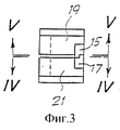
на фиг. 3 представлен локальный передний вид по линии III-III на фиг. 2;
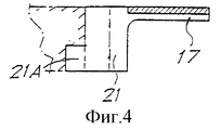
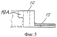
на фиг. 4 и 5 представлены локальные сечения по линиям IV-IV и V-V на фиг. 2 и 3;
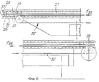
на фиг. 6 представлен боковой вид по линии VI-VI на фиг. 1;
на фиг. 7-9 представлен увеличенный подробный вид согласно фиг. 1 в трех последовательных фазах цикла выгрузки пачки или группы предметов;
на фиг. 10 представлено продольное сечение средства выгрузки предметов по линии X-X на фиг. 11;
на фиг. 11 представлен вид в плане и в частичном сечении приблизительно по линии XI-XI на фиг. 10;
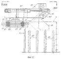
на фиг. 12 представлен локальный вид спереди удерживающего ножа для стопки предметов по линии XII-XII на фиг. 13;
на фиг. 13 представлен вид по линии XIII-XIII на фиг. 12 с удаленными частями.The invention can be better understood from the description and from the accompanying figures, which show a practical, non-limiting example of the invention. In the figures:
in FIG. 1 is a plan view of a device according to the invention mounted on a bending machine for making napkins;
in FIG. 1A and 1B show two parts in which an asterisk can be made for phase displacement of sliders carrying separating fingers;
in FIG. 2 shows a local cross section along line II-II in FIG. 1;
in FIG. 3 shows a local front view along line III-III of FIG. 2;
in FIG. 4 and 5 show local sections along lines IV-IV and VV in FIG. 2 and 3;
in FIG. 6 is a side view taken along line VI-VI of FIG. 1;
in FIG. 7-9 are an enlarged detail view of FIG. 1 in three consecutive phases of the cycle of unloading a pack or group of objects;
in FIG. 10 is a longitudinal section through a means for unloading items along line XX in FIG. eleven;
in FIG. 11 is a plan and partial sectional view taken approximately along line XI-XI in FIG. ten;
in FIG. 12 is a local front view of a holding knife for stacking items along line XII-XII in FIG. thirteen;
in FIG. 13 is a view along line XIII-XIII in FIG. 12 with parts removed.
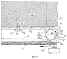
На прилагаемых фигурах позициями 1 и 3 обозначены два гибочных ролика гибочной машины для формирования стопки P салфеток. Гибочные ролики 1 и 3, которые поворачиваются вокруг двух вертикальных осей A и B, имеют кольцеобразные канавки 1A, 3A, которые вмещают криволинейные рычаги 5 и 7, отделяющие согнутый материал от ролика и толкающие его к стопке P ранее образованных предметов, покидающих машину. Непрерывный материал N в виде полосы, который может быть сложен по продольной линии, подают в горловину, образованную между двумя роликами, причем эти ролики представляют собой взаимосвязанные системы известного типа, которые сгибают материал, покидающий горловину, один раз вокруг ролика 1 и один раз вокруг ролика 3, с тем чтобы создать стопку материала, согнутого зигзагообразно. При каждом сгибе соответствующий криволинейный рычаг 5, 7 отделяет материал от ролика и толкает его к ранее образованной стопке P. In the accompanying figures, the
Работа гибочной машины, описанная в сжатой форме, известна и поэтому подробно не представлена. The operation of the bending machine described in compressed form is known and therefore not presented in detail.
Стопка P согнутого материала в виде полосы подталкивается к поперечному ножу 9, который разрезает эту стопку на две части P1 и P2, каждая из которых образована большим количеством салфеток, согнутых в четыре раза. После ножа 9 расположен делитель, который удерживает две части P1 и P2, на которые разрезана стопка, отдельно друг от друга, обеспечивая независимое манипулирование этими двумя частями. The stack P of the bent strip material is pushed towards the transverse knife 9, which cuts this stack into two parts P1 and P2, each of which is formed by a large number of napkins bent four times. After the knife 9, there is a divider that holds the two parts P1 and P2, into which the stack is cut, separately from each other, providing independent manipulation of these two parts.
Стопки P, P1, P2 продвигаются в канале, образованном парой боковых частей 11 и панелью 12 основания, в конце которого пачки салфеток M1, M2...Mn, каждая из которых содержит заданное количество предметов, выгружаются. Piles P, P1, P2 are advanced in a channel formed by a pair of
Для отделения одной пачки салфеток M1 от последующей пачки M2 по боковым сторонам канала для продвижения стопок P, P1, P2 расположены пары отделяющих пальцев 15, 17. Каждый отделяющий палец 15, 17 выполнен за одно целое с соответствующим ползуном 19, 21, который скользит в соответствующей направляющей 23, 25. Две направляющие 23, 25, размещенные одна над другой и отделенные разделительной стенкой 27, изготовленной из материала с низким коэффициентом трения для облегчения скольжения ползунов, расположены с каждой наружной стороны канала для продвижения стопок P, P1, P2. Направляющие 23, 25 формируют закрытый путь и в каждой из них расположено идентичное количество ползунов, соответственно 19 и 21, причем таким образом, что на каждой стороне канала для продвижения каждый ползун 19 и соответствующий палец 15 в направляющей 23 сопрягается с ползуном 21 и соответствующим пальцем 17 в нижней направляющей 25. С каждой стороны канала расположено идентичное количество пар пальцев 15, 17. To separate one pack of napkins M1 from the subsequent pack M2, pairs of separating
С каждой стороны канала для продвижения стопок P, P1, P2 каждая из двух направляющих 23, 25 имеет два прямолинейных участка, параллельных направлению продвижения стопки P, соединенных круглыми концевыми частями, одна их которых примыкает к соответствующему гибочному ролику 1, 3, а другая находится у зоны выгрузки салфетки. On each side of the channel for promoting the stacks P, P1, P2, each of the two
Как показано на фиг. 2-5, ползунам 19, 21 и соответствующим пальцам 15, 17 придана такая форма, что, когда два ползуна 19, 21 расположены друг над другом, верхний ползун 19 входит в зацепление с нижним ползуном 21 таким образом, что когда упомянутый нижний ползун приведен в движение в направлении по часовой стрелке вдоль соответствующей направляющей 25, он движется со своим верхним ползуном 19 в целях, которые будут разъяснены далее. Это достигается посредством ступенчатой формы двух обращенных друг к другу краев отделяющих зубьев 15, 17, подробно показанных на виде спереди согласно фиг. 3. As shown in FIG. 2-5, the
В криволинейных зонах направляющих 23, 25 находится диск 31 с прорезями (вблизи от соответствующего гибочного ролика 1, 3) и звездочка 33 с прорезями (в зоне выгрузки). Диск 31 с прорезями имеет ряд продольных прорезей 31A, глубина которых приблизительно равна толщине двух направляющих 23, 25. Каждая прорезь 31A входит в зацепление с двумя ползунами 19, 21, расположенными друг над другом, посредством выступов 19A, 21A, расположенных на задней части (иными словами на части, противоположной отделяющим пальцам 15, 17) каждого ползуна. При таком расположении постепенное вращение в направлении по часовой стрелке (стрелка f31) диска 31 с прорезями вызывает перенос ползунов 19, 21 парами от соответствующего наружного прямолинейного участка направляющей 23, 25 к внутреннему прямолинейному участку, иными словами к тому, который обращен к стопке P предметов, в то время как относительное положение ползунов 19, 21 одного над другим сохраняется. Постепенное вращение диска 31 с прорезями может быть обеспечено посредством иной соответствующей системы, например посредством механизма с обгонной муфтой, приводимого в движение приводным устройством с линейным цилиндром и поршнем, либо вращательным приводным устройством. In the curved zones of the
Напротив, звездочка 33 с прорезями имеет две группы прорезей 33A, 33B, смещенных друг от друга в угловом направлении приблизительно на 30-40o и расположенных на двух разных уровнях вдоль продольного протяжения звездочки. При этом, поскольку выступы 19A и 21A ползунов 19 и 21 расположены на разной высоте, постепенное вращение звездочки 33 с прорезями в направлении по часовой стрелке (стрелка f33) вызывает перенос ползунов 19, 21 от внутреннего прямолинейного участка к наружному прямолинейному участку соответствующих направляющих и одновременно вызывает смещение в угловом направлении каждого ползуна 19 и соответствующего пальца 15 по отношению к нижнему ползуну 21 и соответствующему пальцу 17. Смещение равно приблизительно 30-40o, иными словами равно угловому смещению прорезей 33A, 33B. Это приводит к существенному перемещению концов пальцев 15, 17 в сторону друг от друга.On the contrary, the
На практике звездочка 33 с прорезями может быть выполнена в виде двух дискообразных частей, которые соединены друг с другом. На фиг. 1A, 1B отдельно показаны две дискообразные части 33X, 33Y в угловом положении по отношению друг к другу, в котором они могут быть смонтированы. Две прорези 33A выполняют в дискообразной части 33X, в то время как две прорези 33B выполняют в дискообразной части 33Y. Такая конфигурация облегчает и упрощает изготовление звездочки 33. Также подобным способом (из идентичных элементов) могут быть выполнены имеющие прорези звездочки 33 с разным смещением между прорезями 33A, 33B. Если две части 33X, 33Y соединены обратимо, одна и та же звездочка 33 с прорезями может регулироваться в соответствии со специальными требованиями к изготовлению с обеспечением переменного и регулируемого смещения между прорезями 33A и 33B. In practice, the
С каждой стороны канала для продвижения стопок P, P1, P2 предметов и параллельно наружному прямолинейному участку каждой пары направляющих 23, 25 проходит непрерывный гибкий элемент 35, идущий вокруг двух шкивов и снабженный щетинками, которые входят в зацепление с пальцами 17, переносимыми от звездочки 33 с прорезями к наружному прямолинейному участку соответствующей направляющей 25, и продвигают их, как указано стрелкой f35, в направлении, противоположном направлению продвижения стопок P, P1, P2 предметов. Как описано выше, форма ползунов 19, 21 и пальцев 15, 17 такова, что продвижение пальца 17 и ползуна 21 посредством щетинок непрерывного гибкого элемента 35 вызывает поступательное движение соответствующего верхнего ползуна 19. Гибкий элемент 35 несет на себе ползуны 19, 21 до тех пор, пока они не будут остановлены диском 31 с прорезями, как показано на фиг. 1. Несколько пар пальцев 15, 17 накапливается позади диска 31 с прорезями и при этом гибкий элемент 35 может проходить под ним благодаря деформации щетинок, которыми снабжен этот элемент. При каждом повороте диска 31 с прорезями пальцы 15, 17, накопленные у него, подталкиваются для сохранения контакта с диском. Количество ожидающих пальцев 15, 17 позади диска 31 с прорезями зависит от размера образуемых пачек предметов M1-Mn; количество неподвижных пар пальцев 15, 17 увеличивается с размером каждой отдельной пачки. On each side of the channel for advancing stacks of objects P, P1, P2 and parallel to the outer rectilinear portion of each pair of
Устройство, описанное до этого места, действует следующим образом. The device described up to this point operates as follows.
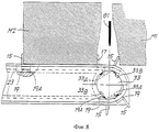
Гибочные ролики 1 и 3 непрерывно вращаются, формируя стопку P, которая затем разрезается ножом 9 на две части P1 и P2. На этой стадии пара отделяющих пальцев 15, 17 находится в ожидании рядом с каждым роликом 1, 3 и остается неподвижной снаружи зоны сгиба. Когда достигнуто заданное количество сгибов с образованием заданного количества салфеток посредством резания, выполняемого ножом 9, с каждой стороны машины соответствующий диск 31 с прорезями поворачивается на один шаг, приводя пару ползунов 19, 21, а следовательно, и соответствующих пальцев 15, 17, расположенных один над другим, из отведенного положения снаружи от гибочных роликов к зоне сгиба в положение, более продвинутое, чем то место, в котором выполняется предыдущий сгиб материала N в виде полосы. Это перемещение делается возможным за счет наличия кольцеобразных канавок в гибочных роликах 1 и 3. Ползуны 19 и 21 полностью высвобождаются из диска 31 с прорезями и могут свободно скользить в направляющих соответственно 23 и 25 вдоль части пути, обращенной к каналу для продвижения. The bending
Когда подача материала N в виде полосы, а следовательно, и сгибание материала с накапливанием согнутого материала в стопке P продолжается, две пары пальцев 15, 17 с двух сторон канала для продвижения, перемещаемые соответствующими дисками 31 с прорезями в зону активного сгибания, остаются зацепленными между одной складкой и последующей складкой и начинают продвигаться вдоль направляющих 23, 25, подталкиваемые упомянутыми стопками P, P1, P2 предметов, продвигающихся в результате действия рычагов 7. Не требуется никаких принудительных средств продвижения отделяющих пальцев вдоль активного участка их пути. When the supply of material N in the form of a strip, and therefore the bending of the material with the accumulation of bent material in the stack P continues, two pairs of
Когда две пары ползунов 19, 21, расположенные друг над другом с двух сторон канала для продвижения стопок P, P1, P2, достигают конца прямолинейного участка направляющих 23, 25, поворот звездочек 33 на один шаг вызывает угловое перемещение верхних отделяющих пальцев 15 (с соответствующими ползунами 19) в сторону от нижних отделяющих пальцев 17 (с соответствующими ползунами 21). Эта операция представлена на фиг. 7 и 8. При этом более продвинутая пачка салфеток M1 перемещается от последующей пачки M2 для облегчения выгрузки пачки M1 посредством разгрузочных средств, которые будут описаны ниже. Каждый нижний ползун 19 удерживается в своем угловом положении, показанном на фиг. 8, посредством наталкивания выступа 19A на периферийную кромку звездочки 33, пока прорезь 33B не войдет а зацепление с соответствующим выступом 19A, поворачивая ползун 19 и соответствующий палец 17 в направлении по часовой стрелке. When two pairs of
Такое последовательное вращение (фиг. 9) каждой из двух звездочек 33 вызывает отцепление нижних отделяющих пальцев 17 от стопки предметов, которая временно удерживается ножом 81, более подробно описанным далее по тексту. Посредством последовательных поворотов на один шаг звездочек 33 с прорезями ползуны 19, 21 подводятся поверх соответствующих непрерывных гибких элементов 35, так что они возвращаются к дискам 31 с прорезями и начинают новый цикл. Such a sequential rotation (Fig. 9) of each of the two
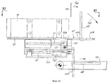
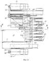
Средства выгрузки отдельных пачек M1, M2...Mn предметов подробно представлены на фиг. 10-12. Means of unloading individual bundles M1, M2 ... Mn of items are presented in detail in FIG. 10-12.
Стенка 12, образующая основание канала для продвижения стопок P, P1, P2 заканчивается в гребнеобразной части 12A, которая взаимодействует с подвижной поверхностью 41, образованной большим количеством полос 41A, несомых кронштейном 43, шарнирно прикрепленным в месте, обозначенном позицией 45, к блоку 47. Каждая полоса 41A имеет прорезь 41B, в которой стержень 49, ортогональный к поверхности 41, зацеплен в отрегулированном положении. Стержни 49 выровнены друг с другом, чтобы образовать вертикальную поверхность для остановки и сдерживания стопки предметов. The
Поверхность 41, образованная полосами 41A, может быть наклонена вокруг оси 45 приводным средством 51, содержащим цилиндр и поршень и несомым плитой 53, которая выполнена за одно целое с блоком 47. Блок 47 с плитой 53, приводным средством 51 и поверхностью 41 также перемещается в направлении двойной стрелки f47. Перемещение обеспечивается за счет того, что полосы 41A, образующие поверхность 41, проникают в пустоты, образованные в гребеночной части 12A поверхности 12 для скольжения стопки P предметов. Управление этим перемещением осуществляется "бесщеточным" электромотором 61 или чем-либо подобным, который передает движение через зубчатый ремень 63 и пару шкивов 65, 67 к штоку 69 с резьбовой нарезкой, с которым входит в зацепление шаровая навинчиваемая гайка 71, несомая блоком 47. Расположение симметрично по обеим сторонам канала для продвижения стопки предметов. Управление двигателем 61 предпочтительно может быть осуществлено по линии электросвязи, при этом двигатель управляет перемещением, как функцией толщины полосы материала N и скорости, с которой этот материал подается и сгибается, в целях, которые будут очевидны из последующего текста. The
Нож 81, приводимый в движение механизмом, отдельно и подробно представленным на фиг. 12 и 13, расположен над поверхностью 41. Нож 81 жестко прикреплен к валу 83, который проходит параллельно направлению продвижения стопок P, P1, P2 предметов, таким образом, что он совершает колебания совместно с валом вокруг оси вала. Вал 83 посредством рычага 85 жестко прикреплен к системе 87, состоящей из цилиндра и поршня, которая вызывает его колебания вокруг своей оси, чтобы вызвать колебания ножа 81 между верхним положением, в котором он отведен от стопок P, P1, P2 (показанным на фиг. 12 сплошными линиями), и нижним положением (показанным на фиг. 12 пунктирными линиями), в котором стопка предметов покоится на ноже. The
Опора 81A ножа (фиг. 13) также жестко прикреплена к штоку 88 дополнительного приводного устройства 89, включающего в себя цилиндр и поршень, которое перемещает нож 81 в направлении, параллельном направлению продвижения стопки P. The
Описанное здесь расположение симметрично, а пары ножей 81 находятся вблизи друг от друга, по одному для каждой части P1, P2 стопки предметов, выпускаемых из машины. The arrangement described here is symmetrical, and the pairs of
Операции по выгружению пачек предметов происходят следующим образом. Operations for unloading packs of items are as follows.
Вначале стержни 49 занимают свое положение, ближайшее к гибочным роликам 1, 3, и передние предметы в стопках P, P1, P2 опираются на стержни 49 и подталкиваются к ним. Когда полосный материал N согнут и роликами 1, 3 с ножом 9 образованы салфетки, стержни перемещаются под регулятор двигателя 61, с тем чтобы обеспечить пространство для новых предметов, выпускаемых из машины. Initially, the
Датчик (не показан) посылает сигнал, когда пара пальцев 15, 17 достигает положения, показанного на фиг. 1. Этот сигнал является разрешением для начала цикла выгрузки пачки M1 салфеток, который происходит следующим образом: пальцы 15, 17 с каждой стороны канала для продвижения перемещаются на расстоянии друг от друга в положение, показанное на фиг. 8; нож 81 опускается и проникает в пространство, создаваемое перемещением пальцев 15, 17 на расстоянии друг от друга, при этом поверхность 41 поворачивается на 90o посредством приводного устройства 51, состоящего из цилиндра и поршня, для опрокидывания пачки M1 на транспортер 91, содержащая большое количество параллельных лент, между которыми проходят полосы 41A и соответствующие стержни 49. На этой стадии палец 15 сопровождает наклонное перемещение пачки салфеток в течение первой части этого наклонного перемещения, удерживая пачку сзади. Последующая пачка M2 удерживается фронтально посредством соответствующего пальца 17 и ножа 81. Когда пачка M1 оседает на транспортер 91 и удаляется транспортером из зоны выгрузки, поверхность 41 вновь приподнимается посредством приводного устройства 51, содержащего цилиндр и поршень, в то время как бесщеточный двигатель вызывает перемещение системы 41, 43, 47, 49 назад в положение, в котором стержни 49 входят в соприкосновение с передней поверхностью пачки M2. Это положение определяется линией электросвязи, управляющей бесщеточным двигателем 61, в соответствии с толщиной полосного материала N и производительностью, а тем временем нож 81 продвигается посредством толкающего действия стопки предметов для обеспечения непрерывной работы сгибающего устройства без существенного увеличения сжатия предметов. Перед возвращением поверхности 41 и стержней 49 в их положение поддерживания для продвижения стопки, посредством звездочек 33 (фиг. 9) осуществляется отвод пальцев 17, так что пачка M2 на следующей стадии удерживается только ножом 81, который свободно продвигается при толкающем действии стопки P, вытягивая шток системы 89, состоящей из цилиндра и поршня. Когда стержни 49 вновь входят в соприкосновение с первой салфеткой продвигающейся стопки, нож 81 отводится вверх посредством приводного устройства 87 и затем возвращается в первоначальное положение посредством приводного устройства 89.A sensor (not shown) sends a signal when the pair of
Как можно видеть на прилагаемых фигурах, приводные устройства, которые обеспечивают выгрузку пачек предметов, сдвоены и симметричны, при этом выгрузка пачек M1 из двух частей P1 и P2, на которые разрезана стопка P, может происходить неодновременно. As can be seen in the attached figures, the drive devices that provide the unloading of packs of objects are doubled and symmetrical, while the unloading of packs M1 from two parts P1 and P2, into which stack P is cut, can occur simultaneously.
Понятно, что на фигурах представлен только пример, являющийся лишь практической демонстрацией изобретения, и что изобретение может быть изменено по форме и расположению без отклонения от объема его руководящей концепции. Указание позиционных номеров в прилагаемых пунктах формулы изобретения выполнено с целью облегчения прочтения формулы изобретения со ссылками на описание и фигуры и не ограничивает объем защиты, определяемый пунктами формулы изобретения. It is clear that the figures show only an example, which is only a practical demonstration of the invention, and that the invention can be changed in shape and location without deviating from the scope of its guiding concept. The reference numbers in the appended claims are made to facilitate the reading of the claims with reference to the description and figures and does not limit the scope of protection defined by the claims.
Claims (27)
Applications Claiming Priority (2)
| Application Number | Priority Date | Filing Date | Title |
|---|---|---|---|
| IT96FI000008A IT1286535B1 (en) | 1996-01-30 | 1996-01-30 | METHOD AND DEVICE TO SEPARATE GROUPS OF LAMINAR PRODUCTS AND FORMING MACHINE INCLUDING SAID DEVICE BETWEEN THEM |
| ITFI96A000008 | 1996-01-30 |
Publications (2)
| Publication Number | Publication Date |
|---|---|
| RU2152347C1 true RU2152347C1 (en) | 2000-07-10 |
| RU98116264A RU98116264A (en) | 2000-07-20 |
Family
ID=11351456
Family Applications (1)
| Application Number | Title | Priority Date | Filing Date |
|---|---|---|---|
| RU98116264/12A RU2152347C1 (en) | 1996-01-30 | 1997-01-24 | Method of and device for separating groups of flat articles from each other and bending machine including such device |
Country Status (17)
| Country | Link |
|---|---|
| US (1) | US6120240A (en) |
| EP (1) | EP0879200B1 (en) |
| JP (1) | JP3933204B2 (en) |
| KR (1) | KR100306960B1 (en) |
| CN (1) | CN1070819C (en) |
| AR (1) | AR005587A1 (en) |
| AT (1) | ATE193270T1 (en) |
| AU (1) | AU1617097A (en) |
| BR (1) | BR9707478A (en) |
| CA (1) | CA2244832C (en) |
| DE (1) | DE69702118T2 (en) |
| ES (1) | ES2146078T3 (en) |
| GR (1) | GR3033540T3 (en) |
| IT (1) | IT1286535B1 (en) |
| RU (1) | RU2152347C1 (en) |
| WO (1) | WO1997028076A1 (en) |
| ZA (1) | ZA97428B (en) |
Cited By (1)
| Publication number | Priority date | Publication date | Assignee | Title |
|---|---|---|---|---|
| RU2745901C2 (en) * | 2016-10-04 | 2021-04-02 | Ульма Пэкэджин Текнолоджикал Сентер, С.Кооп. | Separation system and corresponding packaging machine |
Families Citing this family (16)
| Publication number | Priority date | Publication date | Assignee | Title |
|---|---|---|---|---|
| DE19825328A1 (en) * | 1998-06-05 | 1999-12-09 | Knapp Logistik Automation | Conveyor track arrangement for containers to be filled with articles or bulk goods in a filling station |
| IT1314574B1 (en) * | 2000-02-23 | 2002-12-20 | Perini Fabio Spa | FOLDING DEVICE FOR SHEET MATERIAL, MACHINE FOR THE PRODUCTION OF SHEET MANUFACTURES AND FOLDING METHOD |
| IT1318731B1 (en) * | 2000-08-04 | 2003-09-10 | O M T S R L | EQUIPMENT FOR THE SEPARATION AND THE MUTUAL REMOVAL OF TWO MOBILE CONSECUTIVE SHEETS ACCORDING TO A DIRECTION OF ADVANCE. |
| IT1315042B1 (en) * | 2000-08-14 | 2003-01-27 | Perini Fabio Spa | DEVICE AND METHOD TO SEPARATE AMONG THEIR PACKAGES OF MANUFACTILAMINARIES |
| ATE428664T1 (en) * | 2002-04-03 | 2009-05-15 | Ferag Ag | METHOD AND DEVICE FOR CREATING STACKS OF CONTINUOUSLY FEEDED FLAT OBJECTS |
| ITFI20030182A1 (en) * | 2003-07-01 | 2005-01-02 | Perini Fabio Spa | A TILTING DEVICE TO ROLL UP MANUFACTURED PACKAGES |
| ITFI20030185A1 (en) * | 2003-07-04 | 2005-01-05 | Perini Fabio Spa | BENDING MACHINE WITH TRANSFER DEVICE OF THE |
| ITFI20040144A1 (en) * | 2004-06-25 | 2004-09-25 | Perini Fabio Spa | BENDING MACHINE WITH SUCTION VEHICLES TO FOLD A CONTINUOUS TAPE MATERIAL AND RELATED BENDING METHOD |
| KR20060058939A (en) * | 2004-11-26 | 2006-06-01 | 삼성전자주식회사 | Inkjet image forming apparatus |
| ES2629628T3 (en) * | 2008-05-26 | 2017-08-11 | Ferag Ag | Device and procedure for introducing flat objects into folded printing products |
| IT1392885B1 (en) | 2009-02-13 | 2012-04-02 | Perini Fabio Spa | SEPARATOR DEVICE FOR PACKAGES OF LAMINAR PRODUCTS AND THE MACHINE USING THIS DEVICE |
| GB0917051D0 (en) * | 2009-09-29 | 2009-11-11 | Gant Innovations Ltd | A napkin |
| IT1399479B1 (en) * | 2010-03-15 | 2013-04-19 | Omet Srl | DEVICE AND METHOD FOR SEPARATION AND TRANSPORT OF GROUPS OF FLAT OBJECTS |
| DE102010025224B4 (en) * | 2010-06-23 | 2014-08-21 | Palamides Gmbh | Device and method for transporting flat products |
| AU2015318757B2 (en) | 2014-09-18 | 2018-11-22 | Scott Automation & Robotics Pty Ltd | Safety apparatus for protecting an operator of an electrically powered saw |
| ES2925915T3 (en) | 2018-04-27 | 2022-10-20 | Koerber Tissue S P A | Folding roller and machine comprising said roller |
Family Cites Families (15)
| Publication number | Priority date | Publication date | Assignee | Title |
|---|---|---|---|---|
| FR1465356A (en) * | 1961-11-07 | 1967-01-13 | Remy & Cie E P | Device for grouping a set number of various objects |
| DE1436961C3 (en) * | 1965-08-13 | 1974-01-24 | Hobema Maschinenfabrik Hermann H. Raths, 4000 Duesseldorf | Dispensing device on a folding device for paper handkerchiefs or the like |
| GB1291069A (en) * | 1969-12-01 | 1972-09-27 | Jacob Salomon | Apparatus for arranging substantially laminar articles into spaced groups |
| DE2232023A1 (en) * | 1972-06-30 | 1974-01-17 | Licentia Gmbh | DEVICE FOR CONTINUOUS STACKING OF FLAT SHIPMENTS |
| US4098392A (en) * | 1976-10-26 | 1978-07-04 | Greene William F | Potato chips processing machine |
| DE2732837A1 (en) * | 1977-07-20 | 1979-02-08 | Himmelsbach Papierwarenfab | DEVICE FOR STACKING LEAF-SHAPED OBJECTS |
| JPS557165A (en) * | 1978-06-30 | 1980-01-18 | Orion Kikai Kogyo Kk | Dividing method of folded paper sheets from zigzag folder machine |
| IT1136965B (en) * | 1981-03-27 | 1986-09-03 | Angelo Bartesaghi | DEVICE FOR THE COLLECTION IN PACKAGES OF ESSENTIAL LEAF ELEMENTS |
| US4625957A (en) * | 1984-06-19 | 1986-12-02 | Paper Converting Machine Company | Apparatus for stacking and delivering paper napkins, paper towels, and the like |
| IT1204706B (en) * | 1987-06-10 | 1989-03-10 | Omet Srl | PROCEDURE AND DEVICE FOR SEPARATING A DEFAULT NUMBER OF FLAT OBJECTS, SUCH AS PAPER SHEETS |
| IT1213807B (en) * | 1987-07-28 | 1990-01-05 | Perini Finanziaria Spa | EQUIPMENT FOR THE PRODUCTION AND PACKAGING OF NAPKINS FROM CONTINUOUS TAPE IN PAPER OR OTHER |
| US4824307A (en) * | 1988-02-11 | 1989-04-25 | Tekmax Inc. | Apparatus for vertically stacking battery plates |
| DE4117434A1 (en) * | 1991-05-28 | 1992-12-03 | Winkler Duennebier Kg Masch | METHOD AND DEVICE FOR STACKING |
| IT1252779B (en) * | 1991-07-23 | 1995-06-28 | Perini Fabio Spa | DEVICE TO TRANSFER PACKAGES OF NAPKINS FROM A STACK POWERED BY A FOLDING MACHINE TO A CONVEYOR. |
| US5201823A (en) * | 1992-06-25 | 1993-04-13 | Apv Douglas Machine Corporation | Container metering device having mechanically forced separation |
-
1996
- 1996-01-30 IT IT96FI000008A patent/IT1286535B1/en active IP Right Grant
-
1997
- 1997-01-20 ZA ZA9700428A patent/ZA97428B/en unknown
- 1997-01-24 DE DE69702118T patent/DE69702118T2/en not_active Expired - Lifetime
- 1997-01-24 KR KR1019980705795A patent/KR100306960B1/en not_active IP Right Cessation
- 1997-01-24 CA CA002244832A patent/CA2244832C/en not_active Expired - Fee Related
- 1997-01-24 AU AU16170/97A patent/AU1617097A/en not_active Abandoned
- 1997-01-24 WO PCT/IT1997/000016 patent/WO1997028076A1/en active IP Right Grant
- 1997-01-24 CN CN97191971A patent/CN1070819C/en not_active Expired - Fee Related
- 1997-01-24 JP JP52746797A patent/JP3933204B2/en not_active Expired - Fee Related
- 1997-01-24 EP EP97902564A patent/EP0879200B1/en not_active Expired - Lifetime
- 1997-01-24 ES ES97902564T patent/ES2146078T3/en not_active Expired - Lifetime
- 1997-01-24 AT AT97902564T patent/ATE193270T1/en not_active IP Right Cessation
- 1997-01-24 RU RU98116264/12A patent/RU2152347C1/en not_active IP Right Cessation
- 1997-01-24 BR BR9707478A patent/BR9707478A/en not_active IP Right Cessation
- 1997-01-24 US US09/117,265 patent/US6120240A/en not_active Expired - Fee Related
- 1997-01-29 AR ARP970100350A patent/AR005587A1/en unknown
-
2000
- 2000-05-31 GR GR20000401232T patent/GR3033540T3/en not_active IP Right Cessation
Cited By (1)
| Publication number | Priority date | Publication date | Assignee | Title |
|---|---|---|---|---|
| RU2745901C2 (en) * | 2016-10-04 | 2021-04-02 | Ульма Пэкэджин Текнолоджикал Сентер, С.Кооп. | Separation system and corresponding packaging machine |
Also Published As
| Publication number | Publication date |
|---|---|
| EP0879200A1 (en) | 1998-11-25 |
| KR19990082073A (en) | 1999-11-15 |
| DE69702118D1 (en) | 2000-06-29 |
| ATE193270T1 (en) | 2000-06-15 |
| GR3033540T3 (en) | 2000-09-29 |
| CA2244832C (en) | 2006-06-06 |
| CN1210500A (en) | 1999-03-10 |
| WO1997028076A1 (en) | 1997-08-07 |
| BR9707478A (en) | 1999-04-06 |
| IT1286535B1 (en) | 1998-07-15 |
| ZA97428B (en) | 1997-07-30 |
| CA2244832A1 (en) | 1997-08-07 |
| CN1070819C (en) | 2001-09-12 |
| ITFI960008A0 (en) | 1996-01-30 |
| ES2146078T3 (en) | 2000-07-16 |
| JP2000503953A (en) | 2000-04-04 |
| DE69702118T2 (en) | 2001-02-01 |
| ITFI960008A1 (en) | 1997-07-30 |
| JP3933204B2 (en) | 2007-06-20 |
| AU1617097A (en) | 1997-08-22 |
| US6120240A (en) | 2000-09-19 |
| EP0879200B1 (en) | 2000-05-24 |
| AR005587A1 (en) | 1999-06-23 |
| KR100306960B1 (en) | 2001-11-15 |
Similar Documents
| Publication | Publication Date | Title |
|---|---|---|
| RU2152347C1 (en) | Method of and device for separating groups of flat articles from each other and bending machine including such device | |
| US2414059A (en) | Bunch forming and spacing apparatus | |
| US4625957A (en) | Apparatus for stacking and delivering paper napkins, paper towels, and the like | |
| KR100959726B1 (en) | Machine for the production of flexible material sheets | |
| US4285621A (en) | Apparatus for stacking product | |
| JPH064304B2 (en) | Equipment for making articles such as napkins | |
| EP0294675B1 (en) | A method and device for separating a predetermined number of flat objects, such as sheets of paper | |
| RU98116264A (en) | METHOD AND DEVICE FOR SEPARATING GROUPS OF FLAT PRODUCTS FROM OTHER, AND ALSO A BENDING MACHINE CONTAINING THE MENTIONED DEVICE | |
| DK141359B (en) | Method of packaging groups of articles and machine for carrying out the method. | |
| CA2115499C (en) | Apparatus for transferring paper napkins or similar products from the production machine to stacker means | |
| KR101281942B1 (en) | Device and method for eliminating trimmings from series of products, such as rolls or the like | |
| EP0526419A1 (en) | Apparatus for transferring stacks of serviettes from a pile fed by a folding machine to a conveyor | |
| US5829954A (en) | Rotary motion feeder | |
| US3991909A (en) | Automatic feeding device for delivering articles from a magazine to a conveyor | |
| JPH06199306A (en) | Method and apparatus for supplying, packing and grouping strip-shaped article | |
| JPH0790971B2 (en) | Stacking method and apparatus thereof | |
| US7175382B2 (en) | Device and method for separating packs of laminar products from one another | |
| EP1953090B1 (en) | A device for forming groups of products | |
| EP1305245A1 (en) | Apparatus for separating and moving away from each other two consecutive sheets movable in a feeding direction | |
| US3727495A (en) | Automatic partition cutting machine | |
| US3971685A (en) | Apparatus and procedure for manufacturing articles having a non-woven pile | |
| SU179183A1 (en) | DEVICE FOR MAKING BAGS WITH VALVES FROM THERMOPLASTIC MATERIAL | |
| US3733774A (en) | Apparatus for packaging stacks of flat articles into packages | |
| SU379462A1 (en) | AUTOMATIC MACHINE FOR WRAPPING CANDY "LIGHTNING STOCK" | |
| SU1074776A1 (en) | Rotary machine for gathering sets of articles |
Legal Events
| Date | Code | Title | Description |
|---|---|---|---|
| MM4A | The patent is invalid due to non-payment of fees |
Effective date: 20070125 |