JP3933204B2 - Method and apparatus for separating flat product groups from each other and folding machine comprising said apparatus - Google Patents
Method and apparatus for separating flat product groups from each other and folding machine comprising said apparatus Download PDFInfo
- Publication number
- JP3933204B2 JP3933204B2 JP52746797A JP52746797A JP3933204B2 JP 3933204 B2 JP3933204 B2 JP 3933204B2 JP 52746797 A JP52746797 A JP 52746797A JP 52746797 A JP52746797 A JP 52746797A JP 3933204 B2 JP3933204 B2 JP 3933204B2
- Authority
- JP
- Japan
- Prior art keywords
- group
- pair
- articles
- slider
- along
- Prior art date
- Legal status (The legal status is an assumption and is not a legal conclusion. Google has not performed a legal analysis and makes no representation as to the accuracy of the status listed.)
- Expired - Fee Related
Links
Images


Classifications
-
- B—PERFORMING OPERATIONS; TRANSPORTING
- B65—CONVEYING; PACKING; STORING; HANDLING THIN OR FILAMENTARY MATERIAL
- B65H—HANDLING THIN OR FILAMENTARY MATERIAL, e.g. SHEETS, WEBS, CABLES
- B65H33/00—Forming counted batches in delivery pile or stream of articles
- B65H33/16—Forming counted batches in delivery pile or stream of articles by depositing articles in batches on moving supports
- B65H33/18—Forming counted batches in delivery pile or stream of articles by depositing articles in batches on moving supports with separators between adjacent batches
-
- B—PERFORMING OPERATIONS; TRANSPORTING
- B65—CONVEYING; PACKING; STORING; HANDLING THIN OR FILAMENTARY MATERIAL
- B65H—HANDLING THIN OR FILAMENTARY MATERIAL, e.g. SHEETS, WEBS, CABLES
- B65H45/00—Folding thin material
- B65H45/12—Folding articles or webs with application of pressure to define or form crease lines
- B65H45/20—Zig-zag folders
-
- B—PERFORMING OPERATIONS; TRANSPORTING
- B65—CONVEYING; PACKING; STORING; HANDLING THIN OR FILAMENTARY MATERIAL
- B65H—HANDLING THIN OR FILAMENTARY MATERIAL, e.g. SHEETS, WEBS, CABLES
- B65H33/00—Forming counted batches in delivery pile or stream of articles
- B65H33/02—Forming counted batches in delivery pile or stream of articles by moving a blade or like member into the pile
-
- B—PERFORMING OPERATIONS; TRANSPORTING
- B65—CONVEYING; PACKING; STORING; HANDLING THIN OR FILAMENTARY MATERIAL
- B65H—HANDLING THIN OR FILAMENTARY MATERIAL, e.g. SHEETS, WEBS, CABLES
- B65H45/00—Folding thin material
- B65H45/12—Folding articles or webs with application of pressure to define or form crease lines
- B65H45/28—Folding in combination with cutting
-
- B—PERFORMING OPERATIONS; TRANSPORTING
- B65—CONVEYING; PACKING; STORING; HANDLING THIN OR FILAMENTARY MATERIAL
- B65H—HANDLING THIN OR FILAMENTARY MATERIAL, e.g. SHEETS, WEBS, CABLES
- B65H2301/00—Handling processes for sheets or webs
- B65H2301/40—Type of handling process
- B65H2301/42—Piling, depiling, handling piles
- B65H2301/421—Forming a pile
- B65H2301/4214—Forming a pile of articles on edge
Description
技術分野
本発明は、平らな製品のグループまたはパックを分離する対応した方法と装置に関しており、平らな製品群またはグループは、各々予定された多数の物品を含み、連続して例えばパッケージング機械に送るように供給される。
この型式の装置は、頻繁に紙ナプキンとそれと類似の製品を形成する機械と組み合わされる。通常それらは、物品を送る通路と、その通路と関連して、フォワード部分とリターン部分とから成る閉じた経路に沿って動くことができる複数の分離フィンガーと、リターン部分とを備え、フォワード部分は、物品が進む溝と平行で、分離フィンガーが物品と平行且つ同時に前進する。
技術的背景
紙ナプキンは、垂直軸を備えて狭い通路を形成する、一対の折り重ねローラーから成る形成機械によって形成され、それによって長手方向に沿って普通に折り重なる紙切片材料が供給される。折り重ねローラーに関連した吸引孔またはクランプのシステムは、切片材料を一方と他方で交互につかんで、ローラーの狭い通路を通った後、ジグザグな形に折り重なる。この方法で、折り重なる切片材料の水平なスタックが形成され、スタックを二つの対称的な部分で切る中央ブレードに接して押圧される。二つのスタックは、各々が予め決められたナプキンの数を含むパックかまたはグループに分割されなければならない。様々な分離装置が、これを目的に設計されていた。
折り重ね機の一つの型式では、ナプキンの連続したグループの間の分離は、ナプキンを鋸歯状形態に配置することによって行われ、隣接するグループの間にフィンガーを差し込んで、分離して放出を行う。この型式の機械の例は、米国特許明細書第3,451,521号、ドイツ国特許出願明細書第2,427,635号そして米国特許明細書第5,281,082号に記載されている。
機械の別の型式において、ナプキンは均一なスタックを形成して、機械を出る。形成機械の二つの折り重ねローラーは、折り重ね装置を出る材料のスタックを前進させる溝の両側に配置された二つの連なったコンベアに対応しており、それらのコンベアは、ナプキンの連続したグループの間に挿入される複数の分離フィンガーを運ぶ。各一対のフィンガーは、折り重ねローラーかまたは、ローラーの一つの凹形ハウジングにおける待機位置に配置されており、ナプキンが所望の数に達すると、フィンガーは共に折り重なった製品を放出領域へ前進させる。この様な型式の装置は、日本国特許出願明細書第55 7165号に記載されている。類似であるが、予め切断された平らなシートを供給する機械と組み合わされた分離装置は、フランス国出願明細書第2,398,007号に記載されている。この装置では、分離フィンガーが一時的に、鎖によって示された連続コンベアから離れて、平らな物品を供給するローラーの凹形ハウジングに収容して保持される。平らな物品が所望の数に達した時、フィンガーはコンベアと組合って、機械を出るシートのスタックと同じ方向へ前進し始める。
類似のシステム米国特許明細書第4,938,465号に記載されている。ここでは分離フィンガーが複合磁気システムによって、連続コンベアと組合わされるかまたは、それから離脱される。ナプキン放出領域において、分離フィンガーを、ナプキンは各グループを上から掴み、それらを移動するピックアップ掴み具を案内する。
米国特許明細書第5,393,196が開示する装置は、平らな物品の個別のグループを、間隔をあけた二つの前方ホルダーと後方ホルダーによって、グループ形成領域から離れるように放出領域へ移動させている。形成領域において後方ホルダーが、完成直後のパックと次の第一物品のグループとの間に、別の前方ホルダーと共に、挿入される。そして前記後方ホルダーを、別の前方ホルダーから離れるように移動させて、完成したグループを前進経路に沿って、放出領域へ向かい移動させ、その間こ次のグループが形成領域において形成される。
このシステムは今日、複雑且つ高価であることが知られている。
発明の開示
本発明の目的は、連続して供給される物品のスタックから得られる平らな物品のグループを分ける分離装置を提供することであり、その分離装置は、従来の装置よりも簡単で、より信頼性がある。
本発明の別の目的は、既知の装置よりも経済的な装置を提供することである。
本発明の更なる目的は、ナプキンまたは類似の製品を形成する、効果的且つ速い分離装置を備えた機械を提供することである。
本発明の目的はまた、実用的に柔軟な装置、言い換えれば、複雑な適合運転の必要なく、かなり多数の物品を含んだグループを形成することができ、数が制限された動作部分とアクチュエータを有する装置を提供することである。
これら別の目的と利点は、この技術の熟練者にとって以下の記載を熟読することから明らかでり、上記に示された型式の装置によって得られる。装置は、一方が他方の上に配置され且つ、実質的に同じ長さで案内手段を形成する少なくとも一対の案内手段から成り、前記案内手段に沿って一対のスライダが配置され、前記第一の案内手段に前記一対の第一スライダが配置され、前記第二の案内手段に第二スライダが配置され、各スライダが少なくとも一つの対応する分離フィンガーを支持している。段階的な変位手段は、一時的に前記第一スライダを前記各一対の第二スライダから離れるように動かして、物品の一つのパックを次のグループから離れるように動かし、分離フィンガーの閉じた経路のフォワード部分の端部に配置される。二つのスライダが互いに離れるように動かされる段階の間、好ましくは一方のスライダは、物品を保持するために固定されたままで、他方のスライダを前進させる。
この配置によって、物品の一つのグループを先行するグループから離して放出されるように動かすことを容易にする。各一対の二つの分離フィンガーが、互いに独立しているので、フィンガーが互いに離れる動きは相対的に大きくなり得、グループを傾かさせて放出するように案内させ且つ、例えばブレードのような一時的な保持部材を、放出されるグループと、通路に沿って前進する物品のスタックで止まって配置されている次のグループとの間に位置して挿入することを容易にする。
一対または二対の案内手段は、その一方の案内手段が他方の上に備えられ、それは扱われる物品の型式と、前進通路の形に関連している。分離フィンガーが、(フランス国特許公開明細書第2,398,007号に記されているのと類似の方法で)例えば下方から物品のスタックに貫入している場合、一方が他方の上にまたは、互い側方に配置された一対の案内手段を、前進通路の下に配置するのには充分であり、分離フィンガーの通行用の通路ベースに適合するスロットを有する。逆に言えば、もし分離フィンガーが、側方から物品のスタックに貫入しているすると、好ましくはフィンガーはスタックの両側に配置されている。この場合、装置は二つの一対の案内手段から成り、一方の案内手段は他方の上で物品の前進用通路の両側に沿って配置されている。
装置の可能な実施例では、段階的な変位手段が、それ自体の軸を中心に回転する溝付スプロケットから成り、(例えば二組のスロットの様な)二組の第一組合手段は、前記スプロケットの軸方向伸長部に沿って、異なった高さで配置され且つ、お互いに角度を成してずれている。前記第一組合手段は、前記スライダと関連する第二組合手段(例えば付属部分)と相互作用する。この形態は特に簡単且つ信頼性がある。しかし、例えば線形アクチュエータ、または同類の装置によって運転される一対の揺動アーム様な、別の解決方法を除外してはいない。
有利には、装置の構造を簡単にするため、スライダを閉じた経路の前部に沿った対応する案内手段で自由に摺動するようにさせ、物品によって推進される案内手段を有し、その間に物品が挿入させることができる。このことは、例えば、上記に引用した以前の特許に記載されているように、従来の機械を越える重要な利点である。特に、フィンガーを推進し、推進システムと組合って、それから離脱する全ての複雑なシステムが省略される。
閉じた経路のリターン部分では、スライダが集められて、同じ段階的な変位手段によって押されてもよく、変位手段は前方経路から各一対のスライダを取り出して、それらをリターン部分に運ぶ。逆に、前記閉じた経路の前記リターン部分に関連したリターン作用手段を備えており、スライダを経路のフォワード部分における始めの位置に戻す。作用手段は、シリンダ及びピストン押圧システム、空気式システムまたは、好ましくは柔軟な部材のベルト或いは、それと同等の型式から成り得、スライダと組合わさって、スライダを装置の物品が前進する向きと反対方向に、推進させる。この目的のため、前記案内手段の一方に関連する分離フィンガーと相互作用する剛毛を設けることができる。他方の案内手段と関連した分離フィンガーは、(特別な形成のため)柔軟な部材の剛毛かまたは別の作用手段と組合わさったフィンガーと接続されてもよい。解決方法は、特に簡単で信頼性があり、どの型式の往復動作、同じく圧縮空気の消耗もなくす。
装置は、各一対のスライダを前記閉じた経路から取り出して、形成物品の一つのグループと、それに続くグループとの間のフォワード部分に挿入する挿入部材を有し得る。挿入部材は分離フィンガーを、また折り重ね機械の対応する折り重ねローラーと干渉する適切な軌道をたどらせる。ローラーと装置は関連している。この場合、折り重ねローラは、公知の方法で適切な管状溝を備える。
挿入部材は、それ自体の軸を中心に段階的に回転する溝付ディスクから成り、スライダと関連した対応する組合手段と相互作用する組合要素を備えており、またスライダは一方が他方の上に配置された二つの案内手段に配置される。
様々なシステムが、放出端部に分離フィンガーによって分離される物品のグループを放出する装置を備えられている。特別に有利な実施例において、傾斜表面は物品を前進させる前記通路の端部に、物品を移動するコンベアを備え得る。傾斜表面は、物品の止め具を備え、物品の前進する方向と平行に可動である。動きは、例えばコイル形バネのような可撓性部材の挿入による受容的な方法でまたは、装置の中央ユニットによる適切な方法で制御される適切なアクチュエータによって、得られる。
更に本発明による有利な特徴と実施例を、以下の記載に示す。
また、発明は紙ナプキンまたは類似の製品を製造する折り重ね機械と、例えば折り重ね紙ナプキンの様な、平らな物品のグループを分離する方法に関しており、以下の請求の範囲で詳細に示される。
図面の説明
本発明は、実用的で制限のない本発明の例を示した説明と添付図面からより明確に理解される。
第1図は、本発明による装置がナプキン製造用の折り重ね機械に取り付けられた平面図である。
第1A図と第1B図は、二つの部分を示しており、分離フィンガーを有するスライダを段階的に変位する歯形スプロケットを備えている。
第2図は、第1図のII−II線を介した部分横断面図である。
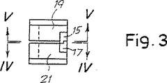
第3図は、第2図のIII−III線を介した正面図である。
第4図と第5図は、第2図と第3図のIV−IV線とV−V線に沿った部分図である。
第6図は、第1図のVI−VI線に沿った側面図である。
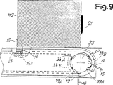
第7図〜第9図は、第1図の拡大詳細図であり、物品のパックまたはグループの放出サイクルを三つの連続した段階で示している。
第10図は、第11図のX−X線を介した物品を放出する手段の長手方向断面図である。
第11図は、ほぼ第10図のXI−XI線を介した平面及び部分断面図である。
第12図は、第13図のXIII−XIII線に沿った、物品のスタックの押圧されブレードの部分正面図である。
第13図は、第12図のXIII−XIII線に沿って、一部を除いた図面である。
発明の実施例の詳細な説明
添付図面で符号1及び3は、ナプキンのスタックPを形成する折り重ね機械における二つの折り重ねローラーを示している。折り重ねローラー1及び3は、二つの垂直軸A及びBを中心に回転し、曲線アーム5及び7を収容する管状溝1A、3Aを有し、それらの曲線アームはローラーから折り重なった材料を取り出して、予め形成された機械を出る物品のスタックPに対して材料を押圧する。連続した切片材料Nは、長手方向の線に沿って折り重なり得て、二つのローラーの間で形成される狭い通路に供給される。それらのローラーは、既知の型式のシステムに対応しており、材料はローラー1の周囲とローラー3の周囲における狭い通路を出て折り重なり、鋸歯状に折り重なる材料のスタックを製造する。折り重ねの度に、対応して曲げられたアーム5、7は、材料をローラーから取り出し、予め形成されたスタックPに向かって材料を押圧する。
概略的な形で記載された折り重ね機械の運転は、既知であり、従って更に詳しくは図示しない。
折り重なった切片材料のスタックPは、スタックを二つの部分P1とP2とにカットする横方向のブレード9に対して押圧され、各々の部分は四つに折り重なった複数のナプキンによって、形成されている。ブレード9でカットされた後に、二つの部分P1、P2に保つ分割装置があり、その中でスタックが互いに分離してカットされて、それら二つの部分を独立して処理させる。
スタックP、P1、P2が、一対の側面ピース11と基部パネル12によって形成された前進通路を前進し、その最後に各々が物品の予定の数が入ったナプキンM1、M2...Mnのグループが放出される。
ナプキンM1の一つのグループを、次のグループM2から分離するため、一対の分離フィンガー15、17は、グループP、P1、P2が前進する通路の側面に配置している。各分離フィンガー15、17は、対応するスライダ19、21と一体型であり、スライダは対応する案内手段23、25で摺動する。二つの案内手段23、25は、一方が他方の上に配置され、スライダを摺動させるため低摩擦係数の材料で作られている分割壁27によって分離されており、スタックP、P1、P2を前進させるために、通路の各側に配置される。案内手段23、25は、閉じた経路を形成しており、その両方に同じ数のスライダ19及び21が配されており、その様な方法では、前進通路の各側で、案内手段23におげる各スライダ19と対応するフィンガー15が、下部案内手段25におけるスライダ21と対応するフィンガー17と適合している。同じ数で一対のフィンガー15、17は、通路の各側に配置されている。
スタックP、P1、P2の前進用通路の各側に、各二つの案内手段23、25が、スタックPの前進方向と平行且つ円形端部と接続された二つの直線部分を有し、一方は対応する折り重ねローラー1、3に隣接し、他方はナプキン放出領域にある。
第2図〜第5図に示されたように、スライダ19、20と対応するフィンガー15、17が、二つのスライダ19、20が上下に配置されている時、上部スライダ19は下部スライダ21と組合う様な方法で、形成されており、前記下部スライダが対応する案内手段25に沿って時計回りの方向に進むと、下部スライダはそれによって、以下に説明する目的のため、上部スライダ19を進ませる様になっている。これは、第3図の正面図に詳細に示されたように、分離歯15、17の二つの向かい合う端部が階段状に形成することによって達成される。
案内手段23、25のカーブする範囲には、(対応する折り重ねローラー1、3の近くには)溝付ディスク31と、(放出領域には)溝付スプロケット33がある。溝付ディスク31は、一組の長手方向スロット31Aを有し、スロットの深さは二つの案内手段23、25の厚さとほぼ同じである。各スロット31Aは、各スライダの後部(言い換えると分離フィンガー15、17と向かい合った部分)に備えられた付属部分19A、21Aにより、一方が他方の上に配置された二つのスライダ19、21と組合っている。これによって、溝付ディスク31の時計回り方向(矢印f31)に段階的な回転が生じて、スライダ19、21が一対で、案内手段23、25の対応する外側直線部分から内側直線部分へ、言い換えると物品のストラックPと向き合う方向に動かされ、その間スライダ19、21の一方が他方の上にある様な相対的な配置に維持される。溝付ディスク31の段階的な回転は、どの適切なシステムによっても生じ、例えば直線シリンダとピストンアクチュエータまたは、回転アクチュエータにより、運転される自在輪機構によって起こる。
逆に、溝付スプロケット33は二組の溝33A、33Bを有し、その溝は互いに約30°〜40°の角度を成してずれて且つ、スプロケットの長手方向の伸長部に沿って、二つの異なった高さに配置される。この方法でスライダ19と21の付属部分19A及び21Aは、異なった高さに配置され、溝付スプロケット33の時計回り方向(矢印f33)の段階的な回転は、スライダ19、21を内側直線部分から対応する案内手段の外側直線部分へ動かし、同時に各スライダ19と、下部スライダ21に関して対応するフィンガー15と、対応するフィンガー17を、角度をつけて変位させる。その変位は、約30°〜40°であり、言い換えればスロット33A、33Bの角度のついたずれと同じである。これはフィンガー15、17の端部が互いに離れるように動かす。このことは重要な意味がある。
実際、溝付スプロケット33が互いに接続された二つの円盤部分から成り得る。第1A図、第1B図では、各々二つの円盤部分33X、33Yが、互いに対応して角度を成しており、それらは適合し得る。二つのスロット33Aは、円盤33Xに形成され、二つのスロット33Bは、円盤部分33Yに形成されている。この形態は、スプロケット33の作りを容易且つ簡単にする。スロット33A、33Bの間で異なった変位をする、溝付スプロケット33は、また(同一要素から)この方法で形成され得る。もし二つの部分33X、33Yが逆転可能に接続されると、同じ溝付スプロケット33は、特別な製造条件により、スロット33A、33Bの間で、変動可能且つ調整可能な変位を行う様に調整され得る。
物品のスタックP、P1、P2が進行する通路の両側で、各一対の案内手段23、25の外側直線部分に平行して、連続する柔軟な部材35が伸びており、その部材は二つのプーリの周囲を走って、フィンガー17と組合う剛毛があり、そのフィンガー17は溝付スプロケット33から、対応する案内手段25の外側直線部分へ動かされ、そして剛毛が矢印f35で示された様な、物品のスタックP、P1、P2の進行方向と反対の向きに推進する。上記のように、スライダ19、21とフィンガー15、17の形状は、連続した柔軟部材35の剛毛によるフィンガー17とスライダ21の進行が、対応する上部スライダ19を推進させる。スライダ19、20は、第1図に示したようにそれらのスライダは、溝付ディスク31によって止められるまで、柔軟な部材35によって支持される。一対のフィンガー15、17の幾つかは、溝付ディスク31の後方に集められ、その間は柔軟部材35がフィンガーの下を走ることができ、剛毛が変形することによってこの部材は提供される。溝付ディスク31の各々の回転によって、それと向かい合う集められたフィンガー15、17は、ディスクとの接触そ保持するために押圧される。溝付ディスク31の後方の待機フィンガー15、17の数は、形成された物品M1〜Mnのグループの寸法に依存しており、固定した一対のフィンガー15、17の数は、各個々のグループの寸法と共に増す。
ここまで述べた装置は、以下のように作動する。
折り重ねローラー1及び3は連続回転してスタックPを形成し、またスタックPはブレード9によって二組のスタックP1、P2にカットされる。この局面で、分離フィンガー15、17は各ローラー1及び3の隣で待機しており、折り重ね領域の外で固定されたままである。折り重ねが予定の数に達すると、ブレード9によってカットされて、予定の数のナプキンを製造し、機械の両側の対応する溝付ディスク31が、一対のスライダ19、21と一方が他方の上に配置された対応するフィンガー15、17は、折り重ねローラーの外側の引出位置から折り重ね領域へ運ばれて、折り重なる位置よりも前進した位置で、切片材料Nが連続して折り重ねられる。この動きは、管状溝が折り重ねローラー1及び3に備えることよって可能になる。スライダ19及び21は、溝付ディスク31から完全に解放されて、案内手段23及び25で各々、前進通路と向かい合う経路部分に沿って摺動するように自由になる。
切片材料Nが供給され、結果的にスタックPとなって折り重なり材料が集まって材料が折り重なり、それが続いて、前進通路の二つの側における二組のフィンガー15、17が、対応する溝付ディスク31によって折り重ね動作領域に推され、その際は始めの折り重ねと次のそれとの間が組み合わされたままになっており、そして物品の前記スタックP、P1、P2によって押圧される案内手段23、25に沿っての前進が始まる。物品の前進はアーム7の動作で行われる。前進に明確な手段はなく、それらの経路の作用部分に沿った分離フィンガーが必要とされる。
二つの一対スライダ19、21は、スタックP、P1、P2の前進用の通路の二つの側部で、一方が他方の上に配置されており、案内手段23、25の直線部分の端部に達すると、歯形スプロケット33の回転は一段階で、(対応するスライダ21を備える)下部分離フィンガー17から離れた、(対応するスライダ19を備えた)上部分離フィンガー15を角度をつけて動かす。この動きは、ナプキンM1のグループを次のパックM2から離して更に前進させ、下記に説明される放出手段によるグループM1の放出を容易にする。各下部スライダ19は、第8図に示したようなその角度のついた位置に、スプロケット33の円形縁に対して付属部分19Aを当接することによって維持され、スロット33Bが対応する付属部分19Aと組合うまで、スライダ19と対応するフィンガー17が時計回りの方向へ回転する。
二つの歯形スプロケット33の連続的な回転(第9図)が、下部分離フィンガー17を、ブレード81により一時的に保持される物品のスタックから離脱させる。これは以下の記載でより詳しく説明する。溝付スプロケット33の一段階での連続的な回転によって、スライダ19、21が対応する連続した柔軟部材35の上に運ばれて、それらは溝付ディスク31に向かって戻り、新しいサイクルが始まる。
物品の各グループM1、M2...Mnの放出手段は、第10図〜第12図に詳細に図示されている。
壁12は、スタックP、P1、P2を前進させる通路の基部を形成し、複数の切片41Aにより形成される可動な表面41と相互作用する櫛形部分12Aで止まる。切片41Aは45で蝶番結合されたブラケット43によってブロック47に支持されている。各切片41Aはスロット41Bを有し、表面41と直交するバー49は、調節可能な位置で組み合っている。バー49は、物品のスタックを抑え且つ止める垂直表面を形成するように、お互い並行に配置されている。
切片41Aによって形成された表面41は、プレート53によって支持されたシリンダー及びピストンアクチュエータ51によって、軸45を中心に傾かせることができ、プレー卜53はブロック47と一体型である。またプレート53を備えたブロック47と、アクチュエータ51と表面41は、二方向矢印f47の方向に動く。その動きは、切片41Aを形成する表面41が、ボイドを貫通するということによって、行える。ボイドは物品のスタックPの摺動のため、表面12の串部分12Aに形成されている。この動きは、ブラシレス電動モータ(“brushless”electric motor)またはそれと同様なもの61によって、制御され、電動モータなど61は、その動作を歯形ベルト63と一対のプーリ65、67を介して、ネジ付きロッド69に伝達される。ネジ付きロッド69は、ブロック47によって支持されたボールネジナット71と組合っている。その配置は、物品のスタックを前進させる通路の両側で対称的な配置である。モータ61は有利には、切片材料Nの厚さに作用し、材料の供給と折り重ねの割合に作用する、モータの動きを制御するPLCによって制御されてもよく、その目的は以下の記載で明らかになる。
ブレード81は、第12図と第13図に詳細に分けて図示されている機構によって運転され、表面41の上に配置されている。ブレード81は、シャフト83に固定されており、シャフト83は物品のスタックP、P1、P2の前進する方向と並行に伸びており、その様な方法でシャフトと一体型でシャフトの軸を中心に往復運動する。シャフト83は、アーム85によって、シリンダー及びピストンシステム87に固定されており、そのシステム87はアームをその軸を中心に往復運動させ、ブレード81の往復運動は上方位置と下方位置との間で行われ、上方位置では(第12図に実線で示されており)スタックP、P1、P2から引き出し、下方位置では(第12図に点線で示されており)物品のスタックがブレードに載る。
またブレード(第13図)の支持部81Aは、別のシリンダー及びピストンアクチュエータ89のロッド88の固定されており、そのアクチュエータ89はブレード81をスタックPの前進方向と平行な向きに動かす。
その配置は、ここでは対称的で一対のブレード81が隣接して設けられ、物品のスタックの各部分P1、P2に対して一つは、機械から出ているように示されている。
物品のグループを放出する動作を、次のように行う。
バー49は、最初に折り重ねロール1及び3に近接する位置へ運ばれ、スタックP、P1、P2の先行する物品をバー49に載せて、それらの物品はバー49に接して押圧される。切片材料Nは折り重ねられ且つ、ナプキンがローラー1、3と、ブレード9によって形成されると、バーがモーター61の制御の下で動いて、機械から出る新しい物品のための空間を作る。
センサ(図示せず)は、一対のフィンガー15、17が第1図に示されている位置に達する時、信号を送る。この信号は、ナプキンのグループM1の放出サイクルを始めさせ、それは次のように行われる。前進通路の両側におけるフィンガー15、17が、第8図に示されているような位置に離すように動かされる。ブレード81は下げられて、フィンガー15、17の離す動きにより形成されるボイドに貫入する。表面41は、シリンダー及びピストンアクチュエータ51によって90°まで回転され、グループM1を複数の平行なベルトから成るコンベア91に傾いて、そのベルトの間を切片41Aと対応するバー49が通過する。この段階で、フィンガー15は、後方からのグループを保持する前記供給動作の第一部を終えてから、ナプキンのパックの傾斜動作を行う。次のグループM2は、対応するフィンガー17とブレード81によって、前方に保持される。グループM1は、コンベア91に配置され、コンベアによって放出範囲から移動させられると、表面41はシリンダ及びピストンアクチュエータ51によって再び上げられ、ブラシレスモータ61が、システム41、43、47、49をバー49がグループM2の前表面と接触する位置へ、戻るように動かす。この位置は、PLCによって決定され、PLCは切片材料Nの厚さと生産率の値により、ブラシレスモータを制御し、故にその間ブレード81が物品のスタックを押圧する動作の下で、折り重ねを連続して動作させるように、物品に対する圧縮を本質的に増すことなく、前進している。表面41とバー49が前進スタックを支持する位置に戻る前に、フィンガー17はスプロケット33(第9図)によって引き出されて、グループM2が、ブレード81のみによる最終段階で保持される。ブレードは、スタックPの押圧動作で自由に前進し、シリンダー及びピストンシステム89のロッドに伸びている。バー49が、再び前進スタックの最初のナプキンに接触する時、ブレード81は、アクチュエータ87によって上方に引かれて、そしてアクチュエータ89によって最初の位置に戻される。
添付図面に見られるように、物品のグループを放出させる装置とアクチュエータは、複式且つ対称的であり、故に二つの部分P1とP2からグループM1の放出され、スタックPがカットされるのが、同時に行われる。
図面は、本発明の実用的な働きを表した単なる一例を示し、本発明はその形式と配置を本発明の指針となる概念の領域から逸脱することなく、変形されることは、明らかである。付随の請求の範囲における参照番号は、説明と図面を参照して請求の範囲における理解を容易にすることを目的としており、請求の範囲によって示された保護領域を制限するものではない。Technical field
The present invention relates to a corresponding method and apparatus for separating flat product groups or packs, each flat product group or group including a number of predetermined articles, such as for continuous delivery to a packaging machine, for example. To be supplied.
This type of device is often combined with a machine that forms a paper napkin and similar products. Typically, they comprise a passage for delivering articles, a plurality of separating fingers that can move along a closed path associated with the passage, consisting of a forward portion and a return portion, and a return portion, Parallel to the groove through which the article travels, the separation finger advances in parallel and simultaneously with the article.
Technical background
A paper napkin is formed by a forming machine consisting of a pair of folding rollers that form a narrow passage with a vertical axis, thereby supplying a paper section material that normally folds along the longitudinal direction. The suction hole or clamping system associated with the folding roller grips the section material alternately on one side and the other and folds in a zigzag shape after passing through the narrow path of the roller. In this way, a horizontal stack of folding section material is formed and pressed against a central blade that cuts the stack in two symmetrical parts. The two stacks must be divided into packs or groups, each containing a predetermined number of napkins. Various separation devices have been designed for this purpose.
In one type of folding machine, the separation between successive groups of napkins is done by placing the napkins in a serrated configuration, with fingers inserted between adjacent groups to separate and discharge. . Examples of this type of machine are described in US Pat. No. 3,451,521, German Patent Application No. 2,427,635 and US Pat. No. 5,281,082.
In another type of machine, the napkin exits the machine, forming a uniform stack. The two folding rollers of the forming machine correspond to two consecutive conveyors arranged on either side of the groove that advance the stack of material exiting the folding device, and these conveyors are a continuous group of napkins. Carries multiple separating fingers inserted between them. Each pair of fingers is placed in a stand-by position on the folding roller or one concave housing of the roller, and when the napkin reaches the desired number, the fingers together advance the folded product to the discharge area. A device of this type is described in Japanese Patent Application No. 55 7165. A similar but separate separator in combination with a machine that supplies pre-cut flat sheets is described in French Patent Specification No. 2,398,007. In this device, the separation fingers are temporarily held away from the continuous conveyor indicated by the chain in a concave housing of a roller that feeds flat articles. When the desired number of flat articles is reached, the fingers combine with the conveyor and begin to advance in the same direction as the stack of sheets exiting the machine.
Similar systems are described in US Pat. No. 4,938,465. Here, the separating fingers are combined with or detached from the continuous conveyor by means of a composite magnetic system. In the napkin discharge area, the separation fingers, the napkin, grab each group from above and guide a pick-up gripper that moves them.
The apparatus disclosed in US Pat. No. 5,393,196 moves individual groups of flat articles to the discharge area away from the grouping area by two spaced apart front and rear holders. In the forming area, a rear holder is inserted between the fresh pack and the next group of first articles together with another front holder. The rear holder is then moved away from the other front holder, and the completed group is moved along the advance path toward the discharge region, while the next group is formed in the formation region.
This system is known today to be complex and expensive.
Disclosure of the invention
It is an object of the present invention to provide a separation device that separates a group of flat articles obtained from a stack of continuously supplied items, which separation device is simpler and more reliable than conventional devices. There is.
Another object of the present invention is to provide a device that is more economical than known devices.
It is a further object of the present invention to provide a machine with an effective and fast separation device that forms a napkin or similar product.
It is also an object of the present invention to form a practically flexible device, in other words, a group containing a very large number of articles without the need for complicated adaptation operations, with a limited number of moving parts and actuators. It is providing the apparatus which has.
These further objects and advantages will be apparent to those skilled in the art from reading the following description and are obtained by an apparatus of the type shown above. The apparatus comprises at least a pair of guide means, one disposed on the other and forming guide means with substantially the same length, and a pair of sliders disposed along the guide means, The pair of first sliders are arranged on the guide means, the second slider is arranged on the second guide means, and each slider supports at least one corresponding separating finger. The stepwise displacement means temporarily moves the first slider away from each pair of second sliders to move one pack of articles away from the next group, and a closed path of separation fingers. At the end of the forward part. During the phase in which the two sliders are moved away from each other, preferably one slider remains fixed to hold the article and advances the other slider.
This arrangement facilitates moving one group of articles away from the preceding group. Since each pair of two separating fingers is independent of each other, the movement of the fingers away from each other can be relatively large, guiding the group to tilt and eject and temporary, eg, a blade It facilitates insertion of the retaining member between the ejected group and the next group that rests on the stack of articles advancing along the passage.
One or two pairs of guide means are provided with one guide means on the other, which is related to the type of article to be handled and the shape of the advance passage. If the separating fingers penetrate into the stack of articles, for example from below (in a manner similar to that described in French Patent Publication No. 2,398,007), one on top of the other or to the side of each other A pair of guide means arranged in the housing is sufficient to be placed under the advance passage and has a slot that fits into the passage base for passage of the separating finger. Conversely, if the separating fingers penetrate into the stack of articles from the side, preferably the fingers are located on both sides of the stack. In this case, the device consists of two pairs of guiding means, one guiding means being arranged on both sides along the opposite sides of the article advancement passage.
In a possible embodiment of the device, the stepwise displacement means consists of a grooved sprocket that rotates about its own axis, and two sets of first combination means (such as two sets of slots), The sprockets are arranged at different heights along the axial extension and are offset from each other at an angle. The first combination means interacts with a second combination means (eg, an attachment) associated with the slider. This configuration is particularly simple and reliable. However, other solutions are not excluded, such as a pair of oscillating arms operated, for example, by linear actuators or similar devices.
Advantageously, in order to simplify the construction of the device, the slider is freely slidable with corresponding guiding means along the front of the closed path and has guiding means driven by the article, Articles can be inserted into This is an important advantage over conventional machines, as described, for example, in previous patents cited above. In particular, all the complex systems that propel the fingers, combine with the propulsion system and leave it are omitted.
In the return part of the closed path, the sliders may be collected and pushed by the same stepped displacement means, which removes each pair of sliders from the forward path and carries them to the return part. Conversely, return actuating means associated with the return portion of the closed path is provided to return the slider to its starting position in the forward portion of the path. The actuating means may comprise a cylinder and piston pressing system, a pneumatic system, or preferably a flexible member belt or equivalent type, in combination with the slider, in the direction opposite to the direction in which the device article is advanced. To promote. For this purpose, bristles can be provided that interact with a separating finger associated with one of the guiding means. The separating finger associated with the other guiding means may be connected to the bristles of the flexible member (for special formation) or fingers combined with another working means. The solution is particularly simple and reliable and eliminates any type of reciprocating movement, as well as exhaustion of compressed air.
The apparatus may have an insertion member that removes each pair of sliders from the closed path and inserts them into the forward portion between one group of formed articles and the following group. The insertion member causes the separation finger to follow a suitable trajectory that also interferes with the corresponding folding roller of the folding machine. The roller and the device are related. In this case, the folding roller is provided with a suitable tubular groove in a known manner.
The insertion member consists of a grooved disk that rotates stepwise about its own axis and comprises a combination element that interacts with a corresponding combination means associated with the slider, and the slider is one above the other. It arrange | positions at the arrange | positioned two guide means.
Various systems are equipped with a device for discharging a group of articles separated by a separation finger at the discharge end. In a particularly advantageous embodiment, the inclined surface may comprise a conveyor for moving the articles at the end of the passage for advancing the articles. The inclined surface is provided with a stop for the article and is movable parallel to the advancing direction of the article. The movement is obtained in a receptive manner, for example by insertion of a flexible member such as a coil spring or by a suitable actuator controlled in a suitable manner by the central unit of the device.
Further advantageous features and embodiments according to the invention are given in the following description.
The invention also relates to a folding machine that produces a paper napkin or similar product and a method for separating a group of flat articles, such as a folded paper napkin, as set forth in detail in the following claims.
Description of drawings
The invention will be more clearly understood from the description and the accompanying drawings, which show practical and non-limiting examples of the invention.
FIG. 1 is a plan view of an apparatus according to the present invention attached to a folding machine for manufacturing a napkin.
FIGS. 1A and 1B show two parts, which are provided with a tooth-shaped sprocket that displaces a slider having separating fingers in stages.
FIG. 2 is a partial cross-sectional view taken along line II-II in FIG.
FIG. 3 is a front view through line III-III in FIG.
4 and 5 are partial views taken along lines IV-IV and VV in FIGS. 2 and 3. FIG.
FIG. 6 is a side view taken along line VI-VI in FIG.
FIGS. 7-9 are enlarged detailed views of FIG. 1, showing the release cycle of a pack or group of articles in three successive stages.
FIG. 10 is a longitudinal cross-sectional view of the means for discharging the article through line XX in FIG.
FIG. 11 is a plan view and a partial cross-sectional view through the line XI-XI of FIG.
FIG. 12 is a partial front view of the pressed blade of the stack of articles along the line XIII-XIII in FIG.
FIG. 13 is a drawing excluding a part along line XIII-XIII in FIG.
Detailed Description of the Embodiments of the Invention
The operation of the folding machine described in schematic form is known and is therefore not shown in more detail.
The folded section stack P is pressed against a lateral blade 9 which cuts the stack into two parts P1 and P2, each part being formed by a plurality of napkins folded in four. . After being cut by the blade 9, there is a splitting device that keeps the two parts P1 and P2, in which the stack is cut separately from each other so that the two parts are processed independently.
Stacks P, P1, P2 advance through an advance passage formed by a pair of
In order to separate one group of napkins M1 from the next group M2, a pair of
On each side of the forward passage of the stacks P, P1, P2, each two guide means 23, 25 have two straight sections parallel to the forward direction of the stack P and connected to a circular end, one of which is Adjacent to the
As shown in FIGS. 2 to 5, when the two
Within the curved range of the guiding means 23, 25 there is a grooved disk 31 (in the vicinity of the corresponding folding rollers 1, 3) and a grooved sprocket 33 (in the discharge area). The
Conversely, the
In fact, the
A continuous
The device described so far operates as follows.
The
The section material N is supplied, resulting in a stack P, the folded material collects and the material folds, followed by two sets of
The two pairs of
Continuous rotation of the two tooth-shaped sprockets 33 (FIG. 9) causes the
The release means for each group of articles M1, M2... Mn is illustrated in detail in FIGS.
The
The
The
A support portion 81A of the blade (FIG. 13) is fixed to another cylinder and a
The arrangement is here symmetrical, with a pair of
The operation of releasing a group of articles is performed as follows.
The
A sensor (not shown) sends a signal when the pair of
As can be seen in the accompanying drawings, the device and the actuator for discharging the group of articles are dual and symmetrical, so that the group M1 is released from the two parts P1 and P2 and the stack P is cut at the same time. Done.
The drawings show only one example illustrating the practical workings of the present invention, and it is clear that the present invention may be modified in form and arrangement without departing from the scope of the concepts that guide the present invention. . Reference numerals in the appended claims are intended to facilitate an understanding of the claims with reference to the description and drawings, and do not limit the protected area indicated by the claims.
Claims (27)
一方が他方の上に配置され且つ、ほぼ同じ長さで、少なくとも一対の案内手段(23,25)を備え、閉じた経路を形成し;
前記案内手段に沿って配置された対のスライダ(19,21)を支持し、前記各対の第一スライダ(19)が前記第一の案内手段(23)に配置され、前記各対の第二スライダ(21)が前記第二の案内手段(25)に配置され、各スライダが少なくとも一つの対応する分離フィンガー(15,17)を支え、各対のスライダのうち二つのフィンガーが、物品の二つの隣接するグループ(M1,M2)の間に挿入され、前記経路に沿って前記物品と共に移動し;
段階的変位手段(33)を備え、段階的変位手段(33)が前記フォワード部分の端部に配置され、一時的に前記各一対のスライダの前記第一スライダ(19)を、各一対の前記第二スライダ(21)から離れるように動かして、物品の一つのグループ(M1)を次のグループ(M2)から離すように動かすこと、
を特徴とする装置。A device that separates a group of articles (M1, M2) from each other and is movable along a path (11, 12) through which the article advances and a closed path associated with the path and comprising a forward part and a return part. A plurality of separating fingers (15, 17), wherein the forward portion of the closed path is parallel to the article advance passage from the finger insertion position to the discharge area of the article, and the separating finger is parallel to and simultaneously with the article. In an apparatus configured to advance along a portion, and along the forward portion, the separation finger returns from the discharge region to the insertion position;
One disposed on the other and of approximately the same length, with at least a pair of guide means (23, 25), forming a closed path;
A pair of sliders (19, 21) arranged along the guide means is supported, and each pair of first sliders (19) is arranged in the first guide means (23), and each pair of first sliders (19, 21) is supported. Two sliders (21) are arranged on the second guide means (25), each slider supporting at least one corresponding separating finger (15, 17), and two fingers of each pair of sliders are Inserted between two adjacent groups (M1, M2) and moved with the article along the path;
Comprising stepwise displacement means (33), wherein the stepwise displacement means (33) is disposed at an end of the forward portion, and temporarily the first slider (19) of each of the pair of sliders, Moving away from the second slider (21) to move one group (M1) of articles away from the next group (M2);
A device characterized by.
物品の各バックまたはグループ(M1、M2)を分離することを特徴とする請求の範囲1〜21のいずれか一つに記載のナプキン製造用の折り重ね機械。Consisting of two rollers (1, 3) and a blade (9), between which the section material (N) is fed to form a stack (P) of material folded in a serrated form, In a folding machine for napkin production in which a blade (9) cuts the stack into two parts of articles (P1, P2),
The folding machine for manufacturing a napkin according to any one of claims 1 to 21, characterized in that each bag or group (M1, M2) of an article is separated.
少なくとも一つの分離フィンガー(15、17)を一つのグループとその次のグループとの間で、挿入位置に挿入し、
分離フィンガーが、物品のスタックと共に、前記前進経路の端部における放出領域まで前進させ、
前記前進経路の端部でスタックの先行グループを放出し、グループを前記分離フィンガーによって次のグループから分離させ、
分離フィンガーを、挿入位置に戻る、
スタックに配置された平らな物品の一つのグループまたはグループ(M1、M2)を、もう一つから分離する方法において、
前記前進経路を形成する少なくとも一対のガイド(23、25)を配置し、前記一対の案内が同じ伸長部を有し;複数の対の前記分離フィンガー(15、17)を、前記前進経路に沿って配置し、前記各対のフィンガーの第一フィンガーが、前記一対のガイドの第一ガイドに沿って案内され、前記各一対のフィンガーの第二フィンガーが、前記一対のガイドの第二ガイドに沿って案内され;
複数の物品と次の物品の各グループの間に、少なくとも一対の前記フィンガーを挿入し;
前記複数対のフィンガーを、前記放出領域に向かって前記前進経路に沿って前進させ;
前記対のフィンガーの第二フィンガーの前に、前記先行グループの後方に配置された対のフィンガーの第一フィンガーを一時的に移動させることによって、前記放出領域で、スタックの各先行グループを、次のグループから分離させこと;
を特徴とする方法。Advance a plurality of groups of articles (M1, M2) along an advance path;
Inserting at least one separating finger (15, 17) in an insertion position between one group and the next group;
A separation finger, along with a stack of articles, advanced to a discharge area at the end of the advance path;
Discharging the preceding group of stacks at the end of the advance path, separating the group from the next group by the separating finger;
Return the separating finger to the insertion position,
In a method of separating one group or group (M1, M2) of flat articles arranged in a stack from another,
Arranging at least a pair of guides (23, 25) forming the advance path, the pair of guides having the same extension; a plurality of pairs of separating fingers (15, 17) along the advance path The first finger of each pair of fingers is guided along the first guide of the pair of guides, and the second finger of each pair of fingers is along the second guide of the pair of guides Guided;
Inserting at least one pair of said fingers between each group of articles and subsequent articles;
Advancing the pairs of fingers along the advance path toward the release region;
Prior to the second finger of the pair of fingers, each preceding group of the stack is next moved in the discharge region by temporarily moving the first finger of the pair of fingers arranged behind the preceding group. Separating from groups of;
A method characterized by.
Applications Claiming Priority (3)
| Application Number | Priority Date | Filing Date | Title |
|---|---|---|---|
| IT96A000008 | 1996-01-29 | ||
| IT96FI000008A IT1286535B1 (en) | 1996-01-30 | 1996-01-30 | METHOD AND DEVICE TO SEPARATE GROUPS OF LAMINAR PRODUCTS AND FORMING MACHINE INCLUDING SAID DEVICE BETWEEN THEM |
| PCT/IT1997/000016 WO1997028076A1 (en) | 1996-01-30 | 1997-01-24 | A method and device for separating groups of flat products from each other, and a folding machine comprising said device |
Publications (3)
| Publication Number | Publication Date |
|---|---|
| JP2000503953A JP2000503953A (en) | 2000-04-04 |
| JP2000503953A5 JP2000503953A5 (en) | 2004-10-28 |
| JP3933204B2 true JP3933204B2 (en) | 2007-06-20 |
Family
ID=11351456
Family Applications (1)
| Application Number | Title | Priority Date | Filing Date |
|---|---|---|---|
| JP52746797A Expired - Fee Related JP3933204B2 (en) | 1996-01-30 | 1997-01-24 | Method and apparatus for separating flat product groups from each other and folding machine comprising said apparatus |
Country Status (17)
| Country | Link |
|---|---|
| US (1) | US6120240A (en) |
| EP (1) | EP0879200B1 (en) |
| JP (1) | JP3933204B2 (en) |
| KR (1) | KR100306960B1 (en) |
| CN (1) | CN1070819C (en) |
| AR (1) | AR005587A1 (en) |
| AT (1) | ATE193270T1 (en) |
| AU (1) | AU1617097A (en) |
| BR (1) | BR9707478A (en) |
| CA (1) | CA2244832C (en) |
| DE (1) | DE69702118T2 (en) |
| ES (1) | ES2146078T3 (en) |
| GR (1) | GR3033540T3 (en) |
| IT (1) | IT1286535B1 (en) |
| RU (1) | RU2152347C1 (en) |
| WO (1) | WO1997028076A1 (en) |
| ZA (1) | ZA97428B (en) |
Families Citing this family (17)
| Publication number | Priority date | Publication date | Assignee | Title |
|---|---|---|---|---|
| DE19825328A1 (en) * | 1998-06-05 | 1999-12-09 | Knapp Logistik Automation | Conveyor track arrangement for containers to be filled with articles or bulk goods in a filling station |
| IT1314574B1 (en) * | 2000-02-23 | 2002-12-20 | Perini Fabio Spa | FOLDING DEVICE FOR SHEET MATERIAL, MACHINE FOR THE PRODUCTION OF SHEET MANUFACTURES AND FOLDING METHOD |
| IT1318731B1 (en) * | 2000-08-04 | 2003-09-10 | O M T S R L | EQUIPMENT FOR THE SEPARATION AND THE MUTUAL REMOVAL OF TWO MOBILE CONSECUTIVE SHEETS ACCORDING TO A DIRECTION OF ADVANCE. |
| IT1315042B1 (en) * | 2000-08-14 | 2003-01-27 | Perini Fabio Spa | DEVICE AND METHOD TO SEPARATE AMONG THEIR PACKAGES OF MANUFACTILAMINARIES |
| DK1350750T3 (en) * | 2002-04-03 | 2009-07-27 | Ferag Ag | Method and apparatus for producing stacks of continuously fed flat articles |
| ITFI20030182A1 (en) * | 2003-07-01 | 2005-01-02 | Perini Fabio Spa | A TILTING DEVICE TO ROLL UP MANUFACTURED PACKAGES |
| ITFI20030185A1 (en) * | 2003-07-04 | 2005-01-05 | Perini Fabio Spa | BENDING MACHINE WITH TRANSFER DEVICE OF THE |
| ITFI20040144A1 (en) * | 2004-06-25 | 2004-09-25 | Perini Fabio Spa | BENDING MACHINE WITH SUCTION VEHICLES TO FOLD A CONTINUOUS TAPE MATERIAL AND RELATED BENDING METHOD |
| KR20060058939A (en) * | 2004-11-26 | 2006-06-01 | 삼성전자주식회사 | Inkjet image forming apparatus |
| AU2009253665B2 (en) * | 2008-05-26 | 2014-10-09 | Ferag Ag | Device and method for inserting flat objects into a folded printed product |
| IT1392885B1 (en) | 2009-02-13 | 2012-04-02 | Perini Fabio Spa | SEPARATOR DEVICE FOR PACKAGES OF LAMINAR PRODUCTS AND THE MACHINE USING THIS DEVICE |
| GB0917051D0 (en) * | 2009-09-29 | 2009-11-11 | Gant Innovations Ltd | A napkin |
| IT1399479B1 (en) * | 2010-03-15 | 2013-04-19 | Omet Srl | DEVICE AND METHOD FOR SEPARATION AND TRANSPORT OF GROUPS OF FLAT OBJECTS |
| DE102010025224B4 (en) * | 2010-06-23 | 2014-08-21 | Palamides Gmbh | Device and method for transporting flat products |
| US10695938B2 (en) | 2014-09-18 | 2020-06-30 | Scott Automation & Robotics Pty Ltd. | Safety apparatus for protecting an operator of an electrically powered saw |
| ES2697500T3 (en) * | 2016-10-04 | 2019-01-24 | Ulma Packaging Tech Ct Coop | Separation system, and associated packaging installation |
| ES2925915T3 (en) | 2018-04-27 | 2022-10-20 | Koerber Tissue S P A | Folding roller and machine comprising said roller |
Family Cites Families (15)
| Publication number | Priority date | Publication date | Assignee | Title |
|---|---|---|---|---|
| FR1465356A (en) * | 1961-11-07 | 1967-01-13 | Remy & Cie E P | Device for grouping a set number of various objects |
| DE1436961C3 (en) * | 1965-08-13 | 1974-01-24 | Hobema Maschinenfabrik Hermann H. Raths, 4000 Duesseldorf | Dispensing device on a folding device for paper handkerchiefs or the like |
| GB1291069A (en) * | 1969-12-01 | 1972-09-27 | Jacob Salomon | Apparatus for arranging substantially laminar articles into spaced groups |
| DE2232023A1 (en) * | 1972-06-30 | 1974-01-17 | Licentia Gmbh | DEVICE FOR CONTINUOUS STACKING OF FLAT SHIPMENTS |
| US4098392A (en) * | 1976-10-26 | 1978-07-04 | Greene William F | Potato chips processing machine |
| DE2732837A1 (en) * | 1977-07-20 | 1979-02-08 | Himmelsbach Papierwarenfab | DEVICE FOR STACKING LEAF-SHAPED OBJECTS |
| JPS557165A (en) * | 1978-06-30 | 1980-01-18 | Orion Kikai Kogyo Kk | Dividing method of folded paper sheets from zigzag folder machine |
| IT1136965B (en) * | 1981-03-27 | 1986-09-03 | Angelo Bartesaghi | DEVICE FOR THE COLLECTION IN PACKAGES OF ESSENTIAL LEAF ELEMENTS |
| US4625957A (en) * | 1984-06-19 | 1986-12-02 | Paper Converting Machine Company | Apparatus for stacking and delivering paper napkins, paper towels, and the like |
| IT1204706B (en) * | 1987-06-10 | 1989-03-10 | Omet Srl | PROCEDURE AND DEVICE FOR SEPARATING A DEFAULT NUMBER OF FLAT OBJECTS, SUCH AS PAPER SHEETS |
| IT1213807B (en) * | 1987-07-28 | 1990-01-05 | Perini Finanziaria Spa | EQUIPMENT FOR THE PRODUCTION AND PACKAGING OF NAPKINS FROM CONTINUOUS TAPE IN PAPER OR OTHER |
| US4824307A (en) * | 1988-02-11 | 1989-04-25 | Tekmax Inc. | Apparatus for vertically stacking battery plates |
| DE4117434A1 (en) * | 1991-05-28 | 1992-12-03 | Winkler Duennebier Kg Masch | METHOD AND DEVICE FOR STACKING |
| IT1252779B (en) * | 1991-07-23 | 1995-06-28 | Perini Fabio Spa | DEVICE TO TRANSFER PACKAGES OF NAPKINS FROM A STACK POWERED BY A FOLDING MACHINE TO A CONVEYOR. |
| US5201823A (en) * | 1992-06-25 | 1993-04-13 | Apv Douglas Machine Corporation | Container metering device having mechanically forced separation |
-
1996
- 1996-01-30 IT IT96FI000008A patent/IT1286535B1/en active IP Right Grant
-
1997
- 1997-01-20 ZA ZA9700428A patent/ZA97428B/en unknown
- 1997-01-24 AT AT97902564T patent/ATE193270T1/en not_active IP Right Cessation
- 1997-01-24 JP JP52746797A patent/JP3933204B2/en not_active Expired - Fee Related
- 1997-01-24 WO PCT/IT1997/000016 patent/WO1997028076A1/en active IP Right Grant
- 1997-01-24 AU AU16170/97A patent/AU1617097A/en not_active Abandoned
- 1997-01-24 DE DE69702118T patent/DE69702118T2/en not_active Expired - Lifetime
- 1997-01-24 RU RU98116264/12A patent/RU2152347C1/en not_active IP Right Cessation
- 1997-01-24 CN CN97191971A patent/CN1070819C/en not_active Expired - Fee Related
- 1997-01-24 KR KR1019980705795A patent/KR100306960B1/en not_active IP Right Cessation
- 1997-01-24 EP EP97902564A patent/EP0879200B1/en not_active Expired - Lifetime
- 1997-01-24 BR BR9707478A patent/BR9707478A/en not_active IP Right Cessation
- 1997-01-24 ES ES97902564T patent/ES2146078T3/en not_active Expired - Lifetime
- 1997-01-24 US US09/117,265 patent/US6120240A/en not_active Expired - Fee Related
- 1997-01-24 CA CA002244832A patent/CA2244832C/en not_active Expired - Fee Related
- 1997-01-29 AR ARP970100350A patent/AR005587A1/en unknown
-
2000
- 2000-05-31 GR GR20000401232T patent/GR3033540T3/en not_active IP Right Cessation
Also Published As
| Publication number | Publication date |
|---|---|
| CA2244832C (en) | 2006-06-06 |
| CN1070819C (en) | 2001-09-12 |
| EP0879200B1 (en) | 2000-05-24 |
| AU1617097A (en) | 1997-08-22 |
| CA2244832A1 (en) | 1997-08-07 |
| JP2000503953A (en) | 2000-04-04 |
| RU2152347C1 (en) | 2000-07-10 |
| AR005587A1 (en) | 1999-06-23 |
| ES2146078T3 (en) | 2000-07-16 |
| IT1286535B1 (en) | 1998-07-15 |
| BR9707478A (en) | 1999-04-06 |
| ATE193270T1 (en) | 2000-06-15 |
| ITFI960008A1 (en) | 1997-07-30 |
| CN1210500A (en) | 1999-03-10 |
| KR100306960B1 (en) | 2001-11-15 |
| DE69702118D1 (en) | 2000-06-29 |
| ITFI960008A0 (en) | 1996-01-30 |
| WO1997028076A1 (en) | 1997-08-07 |
| EP0879200A1 (en) | 1998-11-25 |
| DE69702118T2 (en) | 2001-02-01 |
| KR19990082073A (en) | 1999-11-15 |
| US6120240A (en) | 2000-09-19 |
| GR3033540T3 (en) | 2000-09-29 |
| ZA97428B (en) | 1997-07-30 |
Similar Documents
| Publication | Publication Date | Title |
|---|---|---|
| JP3933204B2 (en) | Method and apparatus for separating flat product groups from each other and folding machine comprising said apparatus | |
| KR930007727B1 (en) | Apparatus for folding and stacking napkins from a continuous web of paper | |
| FI63690C (en) | ANORDNING FOER AVSKILJANDE AV BITAR AV ETT PLATT MATERIAL | |
| DK141359B (en) | Method of packaging groups of articles and machine for carrying out the method. | |
| IL170430A (en) | Device and method for eliminating trimmings from series of products, such as rolls or the like | |
| GB2161147A (en) | Stacking and delivering paper napkins etc | |
| EP3694781A1 (en) | Tissue log saw conveyor with independent lane control cutting and variable conveyor flight length | |
| JPH05213440A (en) | Device for transferring group of piled napkin to conveyor from row of napkin feed from folder | |
| EP0428361A1 (en) | Gum wrapping machine | |
| ITBO970348A1 (en) | DEVICE AND METHOD FOR THE FORMATION OF ORDERED STACKS OF SHEETS OR GROUPS OF SHEETS, IN PARTICULAR BANKNOTES | |
| JPH034468B2 (en) | ||
| EP0972708B1 (en) | Device for feeding blanks on a packing machine | |
| EP0048104A1 (en) | Article handling apparatus | |
| HU189618B (en) | Apparatus for continuous producing corrugated paper band | |
| EP1511602B1 (en) | Device for eliminating end trimmings from a roll or the like | |
| JP2003267625A (en) | Web cutting tuck folding machine | |
| JP2004505871A (en) | Method and apparatus for separating packs of laminated products from each other | |
| US4238273A (en) | Rod applicator mechanism for machine for making hanging file folders | |
| CN111683887B (en) | Device for folding sheets of paper or similar material, in particular information sheets | |
| CA1328168C (en) | Bow making machine and apparatus | |
| EP0471134A1 (en) | Device for the accumulation of bags made of thermoplastic film downstream of the machine which produces them | |
| SU1715698A1 (en) | Device for assembling sets of printed items |
Legal Events
| Date | Code | Title | Description |
|---|---|---|---|
| A131 | Notification of reasons for refusal |
Free format text: JAPANESE INTERMEDIATE CODE: A131 Effective date: 20060117 |
|
| A601 | Written request for extension of time |
Free format text: JAPANESE INTERMEDIATE CODE: A601 Effective date: 20060417 |
|
| A602 | Written permission of extension of time |
Free format text: JAPANESE INTERMEDIATE CODE: A602 Effective date: 20060605 |
|
| A521 | Request for written amendment filed |
Free format text: JAPANESE INTERMEDIATE CODE: A523 Effective date: 20060718 |
|
| A131 | Notification of reasons for refusal |
Free format text: JAPANESE INTERMEDIATE CODE: A131 Effective date: 20060912 |
|
| A521 | Request for written amendment filed |
Free format text: JAPANESE INTERMEDIATE CODE: A523 Effective date: 20061212 |
|
| TRDD | Decision of grant or rejection written | ||
| A01 | Written decision to grant a patent or to grant a registration (utility model) |
Free format text: JAPANESE INTERMEDIATE CODE: A01 Effective date: 20070213 |
|
| A61 | First payment of annual fees (during grant procedure) |
Free format text: JAPANESE INTERMEDIATE CODE: A61 Effective date: 20070313 |
|
| R150 | Certificate of patent or registration of utility model |
Free format text: JAPANESE INTERMEDIATE CODE: R150 |
|
| LAPS | Cancellation because of no payment of annual fees |