RU2149367C9 - Device for diagnostics of pipelines - Google Patents
Device for diagnostics of pipelines Download PDFInfo
- Publication number
- RU2149367C9 RU2149367C9 RU0099119837A RU99119837A RU2149367C9 RU 2149367 C9 RU2149367 C9 RU 2149367C9 RU 0099119837 A RU0099119837 A RU 0099119837A RU 99119837 A RU99119837 A RU 99119837A RU 2149367 C9 RU2149367 C9 RU 2149367C9
- Authority
- RU
- Russia
- Prior art keywords
- sensors
- module
- pipe
- magnetic field
- magnetic
- Prior art date
Links
Images
Landscapes
- Investigating Or Analyzing Materials By The Use Of Magnetic Means (AREA)
- Investigating Or Analyzing Materials By The Use Of Ultrasonic Waves (AREA)
Abstract
Description
Предлагаемое изобретение относится к области диагностики состояния материалов и конструкций и может быть использовано при обследовании технологических и магистральных трубопроводов, в том числе газопроводов, а также трубопроводов первого контура АЭС внутритрубными диагностическими снарядами.The present invention relates to the field of diagnostics of the state of materials and structures and can be used in the examination of technological and main pipelines, including gas pipelines, as well as pipelines of the primary circuit of nuclear power plants with in-tube diagnostic shells.
Известна внутритрубная ультразвуковая установка для контроля состояния трубопроводов, состоящая из транспортирующего модуля, несущего систему пьезоэлектрических преобразователей, электронные устройства возбуждения преобразователей, приема, усиления и обработки сигналов, а также блок определения координат зоны контроля и кабель для передачи информации в накопительное устройство, расположенное вне трубопровода. Круговая решетка приемно-излучающих преобразователей осесимметрично расположена на некотором расстоянии от внутренней стенки трубы. Акустический контакт обеспечивается жидкостью - водой или нефтью, обычно находящейся в трубе [1].Known in-line ultrasonic installation for monitoring the condition of pipelines, consisting of a transporting module carrying a system of piezoelectric transducers, electronic devices for exciting transducers, receiving, amplifying and processing signals, as well as a unit for determining the coordinates of the control zone and a cable for transmitting information to a storage device located outside the pipeline . The circular lattice of the receiving-emitting transducers is axisymmetrically located at a certain distance from the inner wall of the pipe. Acoustic contact is provided by a liquid - water or oil, usually located in a pipe [1].
Применение этого устройства ограничено, так как расположенные по кругу преобразователи, одинаково перпендикулярно ориентированные к внутренней поверхности трубы, не позволяют выявлять трещины в металле, что приводит к низкой достоверности результатов контроля.The use of this device is limited, because the transducers located in a circle, equally perpendicular to the inner surface of the pipe, do not allow to detect cracks in the metal, which leads to low reliability of the control results.
Общеизвестно большое количество вариантов устройств для ультразвукового контроля трубопроводов, представляющих собой диагностические снаряды, перемещаемые внутри контролируемых трубопроводов потоком транспортируемого продукта и содержащие транспортирующий, измерительный и служебный модули, осуществляющие выявление дефектов металла трубопроводов ультразвуковыми колебаниями через жидкий транспортируемый продукт [2, 3]. Измерительный модуль таких устройств содержит акустическую приемно-излучающую систему, состоящую из пьезоэлектрических преобразователей, закрепленную на корпусе модуля, многоканальный усилитель с первичной обработкой принятых сигналов, генератор возбуждающих импульсов. Служебный модуль содержит синхронизатор, блоки определения координат зоны контроля и параметров движения устройства, а также блок сортировки и первичной обработки собранной информации, блок накопления информации и систему энергообеспечения.It is well known that there are a large number of options for devices for ultrasonic inspection of pipelines, which are diagnostic shells that are transported inside controlled pipelines by a stream of transported product and contain transporting, measuring, and service modules that detect defects in pipeline metal by ultrasonic vibrations through a liquid transported product [2, 3]. The measuring module of such devices contains an acoustic receiving-emitting system, consisting of piezoelectric transducers, mounted on the module housing, a multi-channel amplifier with primary processing of the received signals, an excitation pulse generator. The service module contains a synchronizer, blocks for determining the coordinates of the control zone and the parameters of the device’s movement, as well as a block for sorting and primary processing of the collected information, an information storage unit, and an energy supply system.
Дефектоскопия всего объема металла трубы достигается тем, что применяют акустические системы, содержащие большое количество излучающих и приемных преобразователей, располагаемых таким образом, чтобы перекрывались участки поверхности трубы, через которые вводят УЗ импульсы. Для выявления разноориентированных дефектов применяют две и более подобных систем, состоящих в общей сложности более чем из 500 ультразвуковых преобразователей, располагаемых под разными углами к оси трубы и требующих обеспечения определенной последовательности их работы для исключения взаимного влияния.Flaw detection of the entire volume of the pipe metal is achieved by using acoustic systems containing a large number of emitting and receiving transducers arranged so that sections of the pipe surface are blocked through which ultrasonic pulses are introduced. To identify misoriented defects, two or more similar systems are used, consisting of a total of more than 500 ultrasonic transducers located at different angles to the pipe axis and requiring a certain sequence of their work to avoid mutual influence.
Очевидные недостатки известных способов и устройств - низкие достоверность и производительность контроля, определяются малой информативностью сигналов и зависимостью выявляемости дефектов от их ориентации.The obvious disadvantages of the known methods and devices are the low reliability and performance of the control, determined by the low information content of the signals and the dependence of the detection of defects on their orientation.
Однако общим серьезным недостатком упомянутых устройств являются ограничения области применения, связанные с необходимостью использования для создания надежного акустического контакта жидкости, заполняющей трубопровод. Это делает невозможным использование таких устройств для диагностики газопроводов.However, a common serious drawback of these devices is the limitations of the scope associated with the need to use to create reliable acoustic contact of the fluid filling the pipeline. This makes it impossible to use such devices for the diagnosis of gas pipelines.
Известны варианты конструктивных решений, обеспечивающих возможность проведения диагностики газопроводов ультразвуковыми измерительными модулями. В качестве примера можно привести устройство, в котором применены гибкие манжеты, закрывающие в трубе с обеих сторон измерительный модуль вместе с необходимым количеством контактной жидкости, образуя иммерсионную ванну, перемещающуюся вместе со всем устройством внутри контролируемой трубы [4].Known options for design solutions that provide the ability to diagnose pipelines by ultrasonic measuring modules. An example is a device in which flexible cuffs are used that cover the measuring module in the pipe on both sides together with the required amount of contact fluid, forming an immersion bath that moves with the entire device inside the pipe being monitored [4].
Недостатком таких устройств является недостаточная достоверность результатов диагностики, обусловленная низкой надежностью акустического контакта и непредсказуемостью его изменений.The disadvantage of such devices is the lack of reliability of the diagnostic results due to the low reliability of the acoustic contact and the unpredictability of its changes.
Известны устройства для диагностики трубопроводов преимущественно из ферромагнитных материалов, состоящее из транспортирующего и соединенных с ним измерительных и служебных модулей, обеспечивающих обработку первичной информации, запоминание результатов, определение координат и параметров движения устройства и энергоснабжение. Известное устройство [5] содержит два измерительных модуля: магнитный и ультразвуковой.Known devices for the diagnosis of pipelines mainly from ferromagnetic materials, consisting of a transporting and connected measuring and service modules that provide primary information processing, storing results, determining the coordinates and parameters of the device’s movement and power supply. The known device [5] contains two measuring modules: magnetic and ultrasonic.
Ультразвуковой модуль, в принципе, не отличается от приведенных выше и имеет те же недостатки.The ultrasonic module, in principle, does not differ from the above and has the same disadvantages.
Измерительный магнитный модуль внутритрубного диагностического снаряда содержит намагничивающее устройство, систему датчиков измерения нормальной составляющей напряженности рассеиваемого дефектами магнитного поля, соединенных посредством коммутирующего устройства со входами многоканального усилительного блока, выходы которого через блок обработки соединены с запоминающим блоком. Магнитный модуль в этом и других подобных устройствах не способен обнаружить трещины и дефекты типа расслоений, лежащих в плоскостях, параллельных силовым линиям создаваемого магнитного поля, что значительно снижает достоверность и полезность контроля таким дорогостоящим устройством.The measuring magnetic module of the in-tube diagnostic projectile contains a magnetizing device, a system of sensors for measuring the normal component of the intensity of the magnetic field scattered by defects, connected by means of a switching device to the inputs of the multichannel amplifier unit, the outputs of which are connected to the storage unit through the processing unit. The magnetic module in this and other similar devices is not able to detect cracks and defects such as delaminations lying in planes parallel to the lines of force of the generated magnetic field, which significantly reduces the reliability and usefulness of monitoring such an expensive device.
Существенным недостатком магнитного измерительного модуля, ограничивающим область его применения, является то, что применяемые для создания магнитного поля в стенках трубы магнитопроводы, обычно выполняемые в виде щеток из стальной проволоки, склонны к искрообразованию, что категорически недопустимо в газопроводах, и повреждают внутреннюю поверхность трубы, что в ряде случаев недопустимо.A significant drawback of the magnetic measuring module, limiting the scope of its application, is that the magnetic circuits used to create a magnetic field in the pipe walls, usually made in the form of brushes made of steel wire, are prone to sparking, which is categorically unacceptable in gas pipelines, and damage the inner surface of the pipe, which in some cases is unacceptable.
Однако главный недостаток всех известных устройств и традиционных способов, реализуемых ими, заключается в том, что они не позволяют определять степень опасности обнаруженных дефектов и, тем более, обнаруживать "зародыши" дефектов, быстро развивающиеся в условиях эксплуатации и приводящие к "внезапным" разрушениям, бездефектных по результатам традиционной дефектоскопии трубопроводов.However, the main disadvantage of all known devices and traditional methods implemented by them is that they do not allow to determine the degree of danger of the detected defects and, moreover, to detect the "nuclei" of defects that quickly develop under operating conditions and lead to "sudden" damage, defect-free according to the results of traditional flaw detection of pipelines.
Совершенно очевидно, что особую опасность представляют трубопроводы или их участки, у которых приблизился, а в ряде случаев уже наступил срок предполагаемого физического износа материала. Для таких трубопроводов острейшую актуальность приобретают методы определения остаточного ресурса, с целью безопасного продления срока их эксплуатации в реальных условиях, часто приводящих к непредсказуемым изменениям свойств материала. Как показывает практика, гарантировать безопасность эксплуатации таких объектов по результатам, полученным с применением только традиционных средств дефектоскопии, невозможно [6]. Дело в том, что дефектоскопия выявляет уже возникшие дефекты материала. Но дефекты - это конечная стадия деградации материала, и часто время, оставшееся до разрушения конструкции, оказывается слишком малым для предотвращения катастрофы, так как процесс "подрастания" дефектов деградирующего материала в условиях эксплуатации слабо изучен и часто развивается лавинообразно. А если взять усталостные разрушения, то и вовсе нельзя говорить о наличии дефектов в общепринятом смысле.It is quite obvious that the pipelines or their sections, in which the approximate physical wear of the material has approached, and in some cases has already come, are of particular danger. For such pipelines, methods for determining the residual life are gaining urgency in order to safely extend their life in real conditions, often leading to unpredictable changes in material properties. As practice shows, it is impossible to guarantee the safe operation of such objects according to results obtained using only traditional flaw detection tools [6]. The fact is that flaw detection reveals material defects that have already occurred. But defects are the final stage of degradation of the material, and often the time remaining before the destruction of the structure is too short to prevent a catastrophe, since the process of “growing” defects of the degrading material under operating conditions is poorly studied and often develops like an avalanche. And if we take fatigue damage, then it is completely impossible to talk about the presence of defects in the generally accepted sense.
Кроме того, в процессе монтажа или эксплуатации трубопроводов могут возникать локальные тепловые или механические деформации трубы, а также не предусмотренные проектом искривления трубопроводов, вызывающие значительные механические напряжения, не учтенные расчетами конструкции на прочность и приводящие к интенсивным локальным изменениям свойств материала, обуславливающим появление значительного скопления дислокаций, являющегося "зародышем" дефекта. Особенно опасны локальные изгибные напряжения, характеризующиеся сменой знака напряжений и большим градиентом на ограниченном участке трубы. Отсутствие информации об участках с аномальными напряжениями не дает возможности правильно прогнозировать ресурс безопасной эксплуатации трубопроводов вследствие низкой достоверности определения степени опасности обнаруженных дефектов, не говоря уже о "зародышах" потенциально опасных дефектов. Все это существенно снижает эффективность результатов дорогостоящей диагностики трубопроводов.In addition, during the installation or operation of pipelines, local thermal or mechanical deformations of the pipe may occur, as well as pipe bends not provided for in the project, causing significant mechanical stresses, not taken into account by structural calculations for strength and leading to intense local changes in the properties of the material, causing significant accumulation dislocations, which is the "germ" of the defect. Local bending stresses are especially dangerous, characterized by a change in the sign of stresses and a large gradient in a limited section of the pipe. The lack of information about areas with abnormal voltages does not make it possible to correctly predict the resource for safe operation of pipelines due to the low reliability of determining the degree of danger of detected defects, not to mention the “seeds” of potentially dangerous defects. All this significantly reduces the effectiveness of the results of expensive piping diagnostics.
Существенным недостатком всех известных средств определения характеристик напряженно-деформированного состояния металла труб и деталей конструкций является невозможность получения абсолютных количественных значений характеристик, показывающих степень близости фактически существующего напряженно-деформированного состояния в аномальных зонах материала трубы к критическому.A significant drawback of all known means of determining the characteristics of the stress-strain state of a pipe metal and structural parts is the impossibility of obtaining absolute quantitative values of the characteristics showing the degree of closeness of the actual stress-strain state in the anomalous zones of the pipe material to the critical one.
Главной задачей, решаемой предлагаемым изобретением, является повышение эффективности диагностики трубопроводов за счет обеспечения возможности обнаружения "зародышей" будущих дефектов, обусловленных аномалиями структуры материала, возникшими на стадии изготовления трубы или трубопровода в результате нарушения технологии, а также "зародышей" дефектов, обусловленных усталостной, термической или механической поврежденностью материала трубы и процессами деградации материала при длительной эксплуатации объекта.The main task solved by the present invention is to increase the efficiency of pipeline diagnostics by providing the possibility of detecting "nuclei" of future defects caused by anomalies in the structure of the material that arose at the stage of manufacturing a pipe or pipeline as a result of a violation of technology, as well as "nuclei" of defects due to fatigue, thermal or mechanical damage to the pipe material and material degradation processes during long-term operation of the facility.
Второй важной задачей, на решение которой направлено предлагаемое изобретение, является обеспечения возможности количественной оценки степени активности роста обнаруженных дефектов и "зародышей" будущих дефектов, а также количественной оценки изгибных напряжений, возникших в трубопроводе в процессе его монтажа или развившихся при его эксплуатации.The second important task to which the invention is directed is to enable a quantitative assessment of the degree of growth activity of detected defects and “embryos" of future defects, as well as a quantitative assessment of the bending stresses arising in the pipeline during its installation or developed during its operation.
Дополнительными задачами, решаемыми предлагаемым изобретением, являются: обеспечение безопасности работы устройства, надежности при изменении диаметра диагностируемых трубопроводов, а также предохранение внутренних поверхностей трубы от повреждений и упрощение конструктивного выполнения измерительной системы внутритрубного диагностического снаряда.Additional tasks solved by the present invention are: ensuring the safety of the device, reliability when changing the diameter of the diagnosed pipelines, as well as protecting the internal surfaces of the pipe from damage and simplifying the design of the measuring system of the in-tube diagnostic projectile.
Известно упоминание возможности выявления любых аномалий в стенках трубопровода [7] . Однако там речь идет всего лишь об аномалиях толщины стенки или качества поверхности трубы, т.е. о поверхностных дефектах, обнаруживаемых по изменению направления отражения УЗ импульсов.Known mention of the possibility of detecting any anomalies in the walls of the pipeline [7]. However, it deals only with anomalies in wall thickness or pipe surface quality, i.e. surface defects detected by a change in the direction of reflection of ultrasonic pulses.
Решение поставленных задач достигается тем, что в устройстве для диагностики трубопроводов преимущественно из ферромагнитных материалов, содержащем соединенные между собой транспортирующий, по крайней мере, один измерительный модуль и служебные модули для обработки и сортировки первичной информации, запоминания результатов диагностики, определения координат и параметров движения устройства и его энергопитания, измерительный модуль выполнен с возможностью измерения напряженности собственных магнитных полей, создаваемых в металле трубы скоплениями дислокаций и двойников, являющимися зародышами дефектов или областями их интенсивного роста, и включает в себя блоки датчиков нормальной и тангенциальной составляющих напряженности магнитного поля, закрепленные на корпусе модуля по окружности, совпадающей с внутренней поверхностью контролируемой трубы, и многоканальный преобразователь входных сигналов, входы которого соединены с выходами блоков датчиков, а выходы с соответствующими входами служебного модуля обработки первичной информации.The solution of the tasks is achieved by the fact that in the device for the diagnosis of pipelines mainly made of ferromagnetic materials, containing interconnected transporting at least one measuring module and service modules for processing and sorting primary information, storing diagnostic results, determining coordinates and motion parameters of the device and its energy supply, the measuring module is configured to measure the intensity of its own magnetic fields generated in the metal pipes by clusters of dislocations and twins, which are the nuclei of defects or areas of their intensive growth, and includes blocks of sensors of the normal and tangential components of the magnetic field strength, mounted on the module casing along a circle coinciding with the inner surface of the controlled pipe, and a multichannel converter of input signals, inputs which are connected to the outputs of the sensor blocks, and the outputs with the corresponding inputs of the service module for processing primary information.
Кроме того, в устройстве для диагностики трубопроводов каждый из блоков датчиков содержит два датчика измерения тангенциальной составляющей напряженности магнитного поля и датчик нормальной составляющей, ориентированные соответственно вдоль оси трубы, по касательной к окружности расположения датчиков и по ее радиусу.In addition, in the pipeline diagnostic device, each of the sensor blocks contains two sensors for measuring the tangential component of the magnetic field strength and a normal component sensor, oriented respectively along the pipe axis, tangent to the circumference of the sensors and its radius.
Кроме того, в устройстве для диагностики трубопроводов измерительный модуль снабжен многоканальным измерителем магнитной проницаемости металла трубы и коммутатором блоков датчиков, входы которого соединены с выходами датчиков тангенциальной составляющей, а выход соединен с дополнительным входом многоканального преобразователя входных сигналов.In addition, in the device for diagnostics of pipelines, the measuring module is equipped with a multi-channel magnetic permeability meter of the pipe metal and a switch of sensor blocks, the inputs of which are connected to the outputs of the sensors of the tangential component, and the output is connected to an additional input of the multi-channel input signal converter.
Дополнительно, возможен вариант, когда в устройстве для диагностики трубопроводов измерительный модуль снабжен многоканальным измерителем магнитной проницаемости металла трубы с собственными датчиками, количество которых равно количеству блоков датчиков напряженности магнитного поля и которые установлены в непосредственной близости от последних на корпусе модуля по окружности так, чтобы в процессе диагностики датчики измерителя магнитной проницаемости находились за блоками датчиков напряженности магнитного поля.Additionally, a variant is possible when the measuring module in the device for piping diagnostics is equipped with a multi-channel magnetic permeability meter of the pipe metal with its own sensors, the number of which is equal to the number of magnetic field strength sensor blocks and which are installed in the immediate vicinity of the latter on the module’s circumference so that During the diagnostic process, the sensors of the magnetic permeability meter were located behind the blocks of sensors of the magnetic field strength.
Кроме того, в устройстве для диагностики трубопроводов все датчики и блоки датчиков подпружинены в радиальных направлениях.In addition, in the device for diagnosing pipelines, all sensors and sensor blocks are spring-loaded in radial directions.
И, наконец, для расширения функциональных возможностей устройство для диагностики трубопроводов может быть снабжено модулем ультразвуковой диагностики.And finally, to expand the functionality of the device for the diagnosis of pipelines can be equipped with an ultrasonic diagnostic module.
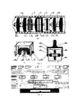
На фиг. 1-5 показаны варианты конструктивного выполнения устройства и чертежи, поясняющие принцип, используемый в работе устройства.In FIG. Figures 1-5 show embodiments of the device and drawings explaining the principle used in the operation of the device.
На фиг. 1 представлен вариант устройства для диагностики трубопроводов, в процессе проведения контроля газопровода, на фиг. 2 - вариант конструкции блока датчиков напряженности собственного магнитного поля дислокаций, на фиг. 3 - блок-схема измерительного модуля, на фиг. 4 - варианты возможного расположения скопления дислокаций, образующих наиболее опасные дефекты и на фиг. 5а, б, в - особенности конфигурации магнитных полей зародышей наиболее опасных дефектов.In FIG. 1 shows an embodiment of a device for diagnosing pipelines during gas pipeline monitoring; FIG. 2 shows a design variant of a block of sensors for the intrinsic magnetic field strength of dislocations, FIG. 3 is a block diagram of a measurement module; FIG. 4 - options for the possible location of a cluster of dislocations that form the most dangerous defects and in FIG. 5a, b, c — features of the configuration of the magnetic fields of the nuclei of the most dangerous defects.
Устройство для диагностики трубопроводов (см. фиг. 1) состоит из одно- или двухблочного транспортирующего модуля - 1, измерительного модуля - 2 и служебного модуля - 3, которые в процессе диагностики перемещаются внутри трубы - 4. Функции измерения напряженности собственного магнитного поля и магнитной проницаемости металла трубы могут быть реализованы в имеющемся в устройстве измерительном модуле, или, как показано на фиг. 1, сосредоточены в отдельном измерительном модуле - 5. Центрирование измерительных модулей и всего устройства относительно оси контролируемой трубы осуществляется упругими манжетами - 6, которые могут выполнять и роль "паруса", принимающего на себя давление транспортируемого газа или другого продукта и продвигающего по трубе все устройство. Для реализации функций измерения напряженности собственного магнитного поля и магнитной проницаемости металла трубы измерительный модуль - 5 содержит блоки датчиков нормальной и тангенциальной составляющих напряженности магнитного поля - 7, закрепленные на корпусе модуля и расположенные по окружности, совпадающей с внутренней поверхностью трубы. В непосредственной близости от блоков датчиков напряженности магнитного поля, но вслед за ними, на корпусе отдельного модуля также по окружности установлены датчики магнитной проницаемости материала трубы - 8. Причем возможны варианты, когда тангенциальные датчики выполняют дополнительную функцию - датчиков измерения магнитной проницаемости. В качестве измерительного дефектоскопического модуля может применяться акустический модуль - 2, имеющий блоки преобразователей - 9. При этом для обеспечения акустического контакта применяются специальная контактная среда - 10, например гель, и герметизирующие манжеты - 11. Для питания электрической энергией всех потребителей устройства могут быть использованы генераторы, располагаемые в служебном модуле и работающие от приводных колес - 12, служащих одновременно измерителем пройденного пути и скорости устройства. Все модули соединены между собой карданными шарнирами - 13, обеспечивающими возможность отслеживания пространственных изгибов оси диагностируемой трубы.A device for diagnosing pipelines (see Fig. 1) consists of a one- or two-unit transporting module - 1, a measuring module - 2 and a service module - 3, which during the diagnostics move inside the pipe - 4. Functions for measuring the intrinsic magnetic field and magnetic field metal permeability of the pipe can be implemented in the measuring module available in the device, or, as shown in FIG. 1, concentrated in a separate measuring module - 5. The centering of the measuring modules and the entire device relative to the axis of the monitored pipe is carried out by elastic cuffs - 6, which can also act as a “sail” that takes on the pressure of the transported gas or other product and moves the entire device through the pipe . To implement the functions of measuring the intrinsic magnetic field strength and magnetic permeability of the pipe metal, the measuring module - 5 contains blocks of sensors for the normal and tangential components of the magnetic field strength - 7, mounted on the module casing and located on a circle coinciding with the inner surface of the pipe. In the immediate vicinity of the sensor blocks of the magnetic field, but on the casing of a separate module, there are also installed sensors of magnetic permeability of the pipe material - 8. Moreover, variants are possible when tangential sensors perform an additional function - sensors for measuring magnetic permeability. An acoustic module - 2, having transducer blocks - 9 can be used as a measuring flaw detector module. In this case, a special contact medium - 10, for example, gel, and sealing cuffs - 11 are used to ensure acoustic contact. For the device to be supplied with electrical energy, the devices can be used generators located in the service module and working from drive wheels - 12, which simultaneously serve as a measure of the distance traveled and the speed of the device. All modules are interconnected by cardanic joints - 13, providing the ability to track spatial bends of the axis of the diagnosed pipe.
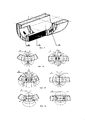
Каждый блок датчиков - 7 измерительного модуля (см. фиг. 2) состоит из датчика нормальной или радиальной составляющей напряженности магнитного поля - 14, представляющего собой сердечник цилиндрической формы с намотанной на него приемной катушкой индуктивности; двух датчиков тангенциальной составляющей, представляющих собой скругленный П-образный или полукольцевой магнитопровод с приемными катушками индуктивности, причем один из датчиков - 15 ориентирован вдоль оси контролируемой трубы, а второй - 16 - перпендикулярно первому, по окружности трубы. Датчики расположены в корпусе - 17 из парамагнитного материала последовательно один над другим так, что торцевые - рабочие поверхности их магнитопроводов образуют симметричную пятилепестковую розетку и залиты магнитонепроницаемым компаундом - 18. Сердечники и магнитопроводы всех датчиков выполнены из магнитопроводящего материала с большой магнитной проницаемостью. Измерительные индуктивности датчиков связаны с блоками обработки посредством кабелей, экранированных друг от друга и от внешних линий (на чертеже не показаны).Each sensor block - 7 of the measuring module (see Fig. 2) consists of a sensor of the normal or radial component of the magnetic field - 14, which is a cylindrical core with a receiving inductor wound around it; two sensors of the tangential component, which are a rounded U-shaped or semi-ring magnetic circuit with receiving inductors, one of the sensors - 15 oriented along the axis of the pipe being monitored, and the second - 16 - perpendicular to the first, around the pipe circumference. The sensors are located in the housing - 17 of paramagnetic material sequentially one above the other so that the end - working surfaces of their magnetic cores form a symmetrical five-petal socket and are filled with a magnetically tight compound - 18. The cores and magnetic cores of all sensors are made of magnetically conductive material with high magnetic permeability. The measuring inductances of the sensors are connected to the processing units via cables shielded from each other and from external lines (not shown in the drawing).
Для обеспечения стабильных условий работы всех датчиков отдельного измерительного модуля - 5 при изменении диаметра контролируемых труб, корпуса блоков датчиков - 7 и 8 снабжены полуосями - 19, закрепленными на корпусе на минимальном расстоянии от рабочей плоскости датчиков и входящими в соответствующие втулки пластинчатой пружины - 20, закрепленной на корпусе модуля.To ensure stable working conditions for all the sensors of a separate measuring module - 5 when changing the diameter of the monitored pipes, the housing of the sensor blocks - 7 and 8 are equipped with semi-axes - 19, mounted on the housing at a minimum distance from the working plane of the sensors and included in the corresponding bushings of the leaf spring - 20, fixed on the module case.
Работает устройство для диагностики трубопроводов следующим образом. Поток транспортируемого трубой продукта перемещает внутри трубы все устройство как поршень (см. фиг. 1). Блоки датчиков - 7 измерительного модуля - 3 измеряют составляющие вектора напряженности магнитного поля, создаваемого зарождающимися и растущими дефектами. Напряжения, наводимые магнитными полями в индуктивностях датчиков, передаются на многоканальный преобразователь входных сигналов - 21 (см. фиг. 3), предназначенный для усиления и первичного преобразования сигналов, соответствующих величинам нормальной, сдвиговой-окружной и сдвиговой-осевой составляющих напряженности магнитного поля. Непосредственно многоканальный преобразователь состоит из трех предварительных усилителей - 22, 23 и 24 измерителя напряженности магнитного поля и коммутируемого предварительного усилителя измерителя магнитной проницаемости - 25, блока аналого-цифрового преобразования - 26 и блока предварительной фильтрации и сжатия информации - 27. Каждый из трех предварительных усилителей, соединенный раздельными входами с соответствующими выходами блоков датчиков, усиливает и коммутирует по заданной программе непрерывно поступающие от каждого из датчиков входные сигналы, преобразуя их в последовательность импульсов, амплитуда которых пропорциональна величине соответствующей измеряемой составляющей напряженности магнитного поля. С выходов предварительных усилителей сигналы поступают на три отдельных входа блока аналого-цифрового преобразования, а с выходов последнего - через блок предварительной фильтрации и сжатия информации, где происходит отсев избыточной информации о медленно меняющихся параметрах, передаются на соответствующие входы блока обработки и запоминания первичной информации - 28 служебного модуля - 3.A device for diagnosing pipelines as follows. The flow of the product transported by the pipe moves the entire device inside the pipe like a piston (see Fig. 1). Blocks of sensors - 7 measuring module - 3 measure the components of the vector of the magnetic field created by nascent and growing defects. Voltages induced by magnetic fields in the inductors of the sensors are transmitted to the multi-channel input signal converter - 21 (see Fig. 3), designed to amplify and initially convert the signals corresponding to the normal, shear-circumferential, and shear-axial components of the magnetic field strength. The multi-channel converter itself consists of three pre-amplifiers - 22, 23 and 24 magnetic field strength meters and a switched pre-amplifier of the magnetic permeability meter - 25, an analog-to-digital conversion unit - 26 and a preliminary filtering and data compression unit - 27. Each of the three pre-amplifiers connected by separate inputs to the corresponding outputs of the sensor blocks, amplifies and commutes according to a given program continuously coming from each of the sensors input signals, converting them into a sequence of pulses, the amplitude of which is proportional to the value of the corresponding measured component of the magnetic field strength. From the outputs of the pre-amplifiers, the signals are fed to three separate inputs of the analog-to-digital conversion unit, and from the outputs of the latter, through the preliminary filtering and information compression unit, where excess information about slowly changing parameters is screened out, they are transmitted to the corresponding inputs of the processing and storing primary information unit - 28 service module - 3.
Источником дополнительной информации, необходимой для определения степени опасности зарождающихся и растущих дефектов, является многоканальный измеритель магнитной проницаемости, который, в случае использования датчиков тангенциальной составляющей, на короткое время, определяемое заданной программой диагностики, переключает их в активный режим измерения магнитной проводимости диагностируемого участка металла, по которой вычисляется магнитная проницаемость. Сигналы с входа многоканального измерителя магнитной проницаемости поступают на дополнительный вход блока аналого-цифрового преобразования, а с выходов последнего, проходя путь, аналогичный пути основных сигналов каналов напряженности магнитного поля, также передаются на соответствующий вход блока обработки и запоминания первичной информации служебного модуля.A source of additional information necessary to determine the degree of danger of incipient and growing defects is a multichannel magnetic permeability meter, which, in the case of using tangential component sensors, for a short time determined by a given diagnostic program, switches them to the active mode of measuring the magnetic conductivity of the diagnosed metal section, by which magnetic permeability is calculated. The signals from the input of the multichannel magnetic permeability meter are fed to the additional input of the analog-to-digital conversion unit, and from the outputs of the latter, following a path similar to the path of the main signals of the channels of the magnetic field strength, they are also transmitted to the corresponding input of the processing unit and storing primary information of the service module.
В случае использования отдельных датчиков измерителя магнитной проницаемости, порядок работы легко понять, пользуясь блок-схемой (см. фиг. 3).In the case of using separate sensors of the magnetic permeability meter, the operating procedure is easy to understand using the flowchart (see Fig. 3).
Представляется необходимым дать некоторые пояснения, касающиеся физического явления генерации зарождающимися и активно развивающимися дефектами собственных магнитных полей.It seems necessary to give some explanations regarding the physical phenomenon of generation by incipient and actively developing defects of intrinsic magnetic fields.
Сущность заложена в малоизвестных и неизученных в аспекте практического применения свойствах дефектов кристаллической структуры металлов - дислокаций. Дислокация, как реально существующий объект, обладает вполне реальными физическими свойствами, обусловленными несбалансированностью электромагнитных полей, вызванной локальным разрушением элементов кристаллической атомной решетки [8] . В случае ферромагнитного материала, элемент решетки представляет собой куб с атомами в его углах, а вся решетка - строгую пространственную структуру. Разрушение такого порядка проявляется как появление полуплоскости, являющейся своеобразным клином, на границах которого оказываются "оторванные" электрические заряды и спиновые моменты. Наличие избыточного количества свободных электронов проводимости по обе стороны границ позволяет компенсировать несбалансированность электрических зарядов, однако "новые" электроны не в состоянии компенсировать разность спиновых моментов, что приводит к появлению элементарного магнитного момента - источника собственного магнитного поля дислокации. Поскольку в материале, даже в ненапряженном состоянии, существует значительное количество дислокаций, то материал представляет собой совокупность произвольно ориентированных "магнитиков", создающих собственное интегральное магнитное поле материала. В идеальном - однородном изотропном материале напряженность магнитного поля, создаваемого магнитными моментами дислокаций, будет равна нулю. Но любая неоднородность материала, свойственная всем реальным материалам, вызывает перемещения и группирование дислокаций [9], что приводит к появлению скоплений дислокаций, которые имеют существенно большие магнитные моменты. Это и является причиной неравномерности напряженности магнитного поля. Поскольку магнитное сопротивление ферромагнитных материалов мало, то магнитные потоки, создаваемые скоплениями дислокаций, векторно суммируясь, будут распространяться во всем объеме исследуемого материала с минимальными потерями, что дает возможность регистрировать скопления дислокаций, находящихся не только на поверхности исследуемой детали, но и в толще материала, и даже на противоположной стороне детали. Этим объясняется высокая чувствительность способа, реализуемого предлагаемым устройством. Однако главное преимущество предлагаемого устройства, вытекающее из особенностей используемого явления, заключается в получении количественной информации. Поскольку дислокация или их скопление является магнитным диполем, то сила, действующая на концы диполя - границы дефекта элемента кристаллической структуры - края будущей трещины, определяется следующей формулой:The essence lies in the little-known and unexplored in the aspect of practical application of the properties of defects in the crystal structure of metals - dislocations. A dislocation, as a real existing object, has very real physical properties due to the imbalance of electromagnetic fields caused by local destruction of the elements of the crystal atomic lattice [8]. In the case of ferromagnetic material, the element of the lattice is a cube with atoms in its corners, and the entire lattice is a strict spatial structure. The destruction of this order manifests itself as the appearance of a half-plane, which is a kind of wedge, at the borders of which there are "torn off" electric charges and spin moments. The presence of an excess of free conduction electrons on both sides of the boundaries makes it possible to compensate for the imbalance of electric charges, but the “new” electrons are not able to compensate for the difference in spin moments, which leads to the appearance of an elementary magnetic moment — a source of the dislocation’s own magnetic field. Since there is a significant number of dislocations in the material, even in an unstressed state, the material is a collection of arbitrarily oriented “magnets” that create their own integral magnetic field of the material. In an ideal homogeneous isotropic material, the magnetic field created by the magnetic moments of the dislocations will be zero. But any heterogeneity of the material, which is characteristic of all real materials, causes dislocation movements and grouping [9], which leads to the appearance of dislocation clusters that have substantially large magnetic moments. This is the reason for the uneven magnetic field strength. Since the magnetic resistance of ferromagnetic materials is small, the magnetic fluxes generated by dislocation clusters, summing vectorly, will propagate in the entire volume of the material under study with minimal losses, which makes it possible to register dislocation clusters located not only on the surface of the investigated part, but also in the thickness of the material, and even on the opposite side of the part. This explains the high sensitivity of the method implemented by the proposed device. However, the main advantage of the proposed device, resulting from the features of the used phenomenon, is to obtain quantitative information. Since the dislocation or their accumulation is a magnetic dipole, the force acting on the ends of the dipole — the boundary of the defect of the element of the crystalline structure — the edges of the future crack, is determined by the following formula:
Fz=Bz⋅Hz⋅Sд, (1)F z = B z ⋅H z ⋅S d , (1)
где: Sд - площадь поверхности, пронизываемая магнитным потоком;where: S d - surface area permeated by magnetic flux;
Bz - проекция магнитной индукции на нормаль к поверхности изделия в зоне максимума напряженности, причем:B z - the projection of magnetic induction on the normal to the surface of the product in the zone of maximum tension, and:
Bz = μa⋅Hz. (2)B z = μ a ⋅H z . (2)
Но поскольку эта поверхность является поверхностью, на которую действует сила магнитного поля, то можно определить величину проекции напряжения, действующего в зоне дислокации или их скопления:But since this surface is a surface on which the magnetic field acts, it is possible to determine the projection of the voltage acting in the dislocation zone or their accumulation:
σz = Fz:Sд = μa⋅(Hz)2. (3)σ z = F z : S d = μ a ⋅ (H z ) 2 . (3)
Таким образом, впервые реализуется количественная оценка величины внутренних напряжений, действующих в зоне зарождающегося или растущего дефекта.Thus, for the first time, a quantitative assessment of the magnitude of internal stresses acting in the zone of a nascent or growing defect is realized.
Такой вариант позволяет определять характеристики напряженно-деформированного состояния материала тонких трубопроводов, испытывающих одноосные нагружения. Проводя аналогичные операции непрерывно или дискретно вдоль трубопровода, можно построить скалярное поле распределения внутренних напряжений.This option allows you to determine the characteristics of the stress-strain state of the material of thin pipelines experiencing uniaxial loading. Carrying out similar operations continuously or discretely along the pipeline, it is possible to construct a scalar field of the distribution of internal stresses.
Кроме того, сравнивая параметры сигналов, принятых диаметрально противоположно расположенными блоками датчиков, можно установить наличие изгибных напряжений и количественно определить их величину.In addition, by comparing the parameters of signals received by diametrically opposed sensor blocks, it is possible to establish the presence of bending stresses and quantify their magnitude.
Для получения более полной информации о характеристиках напряженно-деформированного состояния материала трубопровода в реальных случаях сложного нагружения необходимо дополнительно измерять две тангенциальных составляющих напряженности магнитного поля в тех же точках, где измеряется нормальная составляющая. Затем, используя очевидные вычисления, получить максимальное значение тангенциальной составляющей - Hφ и угол φ между направлением максимума тангенциальной составляющей и одной из осей используемой системы координат. При этом вектор напряженности магнитного поля определяется модулем - |H| и направляющими углами - φ и ξ. Для вычисления модуля - |H| и угла в плоскости, нормальной к поверхности обследуемого объекта, - ξ используют следующие формулы:To obtain more complete information about the characteristics of the stress-strain state of the pipeline material in real cases of complex loading, it is necessary to additionally measure two tangential components of the magnetic field strength at the same points where the normal component is measured. Then, using obvious calculations, get the maximum value of the tangential component - H φ and the angle φ between the direction of the maximum of the tangential component and one of the axes of the coordinate system used. In this case, the magnetic field vector is determined by the module - | H | and guiding angles - φ and ξ. To calculate the modulus - | H | and the angle in the plane normal to the surface of the examined object, - ξ, use the following formulas:
|H| = [(Hz)2+(Hϕ)2]0,5 (4)| H | = [(H z ) 2 + (H ϕ ) 2 ] 0.5 (4)
ξ= arctg(Hz:Hφ). (5)ξ = arctan (H z : H φ ). (5)
Затем, проведя вычисления, аналогичные описанным выше, можно получить полные характеристики вектора внутреннего напряжения в отдельной точке (локальной зоне) и построить векторные поля распределения внутренних напряжений в стенках диагностируемой трубы.Then, having performed calculations similar to those described above, it is possible to obtain the full characteristics of the internal stress vector at a separate point (local zone) and construct vector fields of the distribution of internal stresses in the walls of the diagnosed pipe.
Кроме того, если при вычислениях использовать информацию, получаемую ультразвуковым или другим измерительным модулем, а именно: значение расстояния до аномальной зоны - L, ее толщину - ΔL и площадь зоны - Sз, то можно рассчитать Wз - величину энергии, запасенной в скоплении дислокаций и определяющей активность зарождения или роста трещины:In addition, if in the calculations we use information obtained by an ultrasonic or other measuring module, namely: the distance to the anomalous zone is L, its thickness is ΔL and the area of the zone is S s , then we can calculate W s - the amount of energy stored in the cluster dislocations and determining the activity of nucleation or crack growth:
Wз = 0,5⋅μa⋅|H|2⋅Sз⋅ΔL. (6)W s = 0.5⋅μ a ⋅ | H | 2 ⋅S s ⋅ΔL. (6)
Здесь следует отметить, что приведенные формулы показывают идеологию расчета характеристик напряженно-деформированного состояния материала и могут служить для приближенных расчетов напряжений в тонкостенных трубах. В случае диагностики толстостенных трубопроводов, а также для получения более точных результатов необходимо учитывать геометрию зоны, что отразится на формулах введением функций, описывающих геометрию и характер распределения напряженности магнитного поля, и переходом к интегрированию по поверхности для внутренних напряжений и по объему для энергии. При этом для трубопроводов могут быть разработаны специальные программы.It should be noted here that the above formulas show the ideology of calculating the characteristics of the stress-strain state of a material and can serve for approximate calculations of stresses in thin-walled pipes. In the case of diagnostics of thick-walled pipelines, as well as to obtain more accurate results, it is necessary to take into account the geometry of the zone, which will be reflected in the formulas by introducing functions that describe the geometry and nature of the distribution of the magnetic field strength and the transition to integration over the surface for internal stresses and volume for energy. Moreover, special programs can be developed for pipelines.
Таким образом, предлагаемое устройство для ультразвуковой диагностики трубопроводов, благодаря обеспечению возможности обнаружения и количественной оценки зарождающихся и растущих дефектов, существенно повышает достоверность определения ресурса трубопроводов, что особенно важно для магистральных газопроводов и других труб, жизненно важных для особо ответственных объектов.Thus, the proposed device for ultrasonic diagnostics of pipelines, due to the possibility of detection and quantification of incipient and growing defects, significantly increases the reliability of determining the resource of pipelines, which is especially important for gas pipelines and other pipes that are vital for critical facilities.
Источники информацииSources of information
1. Я де Раад и др. Контроль и опыт, приобретенные при работе с ультразвуковыми внутритрубными установками. Доклад. VII Международная конференция "Морская механика и арктическая инженерия", Хьюстон, 1988 г.1. I de Raad et al. Control and experience gained from working with ultrasonic in-line installations. Report. VII International Conference "Marine Mechanics and Arctic Engineering", Houston, 1988
2. Проспект фирмы Preusag Pipetronix (Германия), 1990 г., с. 10-12.2. Prospectus of the company Preusag Pipetronix (Germany), 1990, p. 10-12.
3. Установка для контроля трубопроводов. Проспект фирмы RTD (Голландия), 1990 г., с. 2-3.3. Installation for monitoring pipelines. Prospectus of the company RTD (Holland), 1990, p. 2-3.
4. Патент ФРГ, DE 19502764 A1, кл. G 01 N 29/04, 01.08.96.4. The patent of Germany, DE 19502764 A1, cl. G 01
5. Герман Розен. Новейшие разработки систем технического контроля трубопроводов на основе применения интеллигентных поршней и метода магнитного потока. Отчет фирмы "Розен инжиниринг", ФРГ, январь 1990 г.5. Herman Rosen. The latest development of piping technical control systems based on the use of intelligent pistons and magnetic flux method. Report of Rosen Engineering, Germany, January 1990
6. Власов В. Т., Марин Б.Н., Лазуткин А. И. Стратегия повышения эксплуатационной надежности трубопроводов бортовых систем теплоснабжения. Доклад 2.27, 15. Российская научно-техническая конференция "Неразрушающий контроль и диагностика", Москва, 28.06.-02.07.99 г.6. Vlasov VT, Marine BN, Lazutkin A. I. Strategy for improving the operational reliability of pipelines of on-board heat supply systems. Report 2.27, 15. Russian Scientific and Technical Conference "Non-Destructive Testing and Diagnostics", Moscow, June 28.-02.07.99
7. Патент Великобритании, заявка GB N 2147102, кл. G 01 N 29/04, 01.05.85 г.7. UK patent application GB N 2147102, CL G 01
8. Ч. Киттель. Элементарная физика твердого тела. - М.: Наука, 1969 г.8. C. Kittel. Elementary solid state physics. - M .: Nauka, 1969
9. Фридман Я. Б. Механические свойства металлов. Ч. 1. Деформация и разрушение. - М.: Машиностроение, 1974 г.9. Friedman Ya. B. Mechanical properties of metals. Part 1. Deformation and destruction. - M.: Mechanical Engineering, 1974.
Claims (6)
Priority Applications (1)
| Application Number | Priority Date | Filing Date | Title |
|---|---|---|---|
| RU0099119837A RU2149367C9 (en) | 1999-09-07 | 1999-09-07 | Device for diagnostics of pipelines |
Applications Claiming Priority (1)
| Application Number | Priority Date | Filing Date | Title |
|---|---|---|---|
| RU0099119837A RU2149367C9 (en) | 1999-09-07 | 1999-09-07 | Device for diagnostics of pipelines |
Publications (2)
| Publication Number | Publication Date |
|---|---|
| RU2149367C1 RU2149367C1 (en) | 2000-05-20 |
| RU2149367C9 true RU2149367C9 (en) | 2020-04-06 |
Family
ID=20224984
Family Applications (1)
| Application Number | Title | Priority Date | Filing Date |
|---|---|---|---|
| RU0099119837A RU2149367C9 (en) | 1999-09-07 | 1999-09-07 | Device for diagnostics of pipelines |
Country Status (1)
| Country | Link |
|---|---|
| RU (1) | RU2149367C9 (en) |
Cited By (1)
| Publication number | Priority date | Publication date | Assignee | Title |
|---|---|---|---|---|
| RU2766370C1 (en) * | 2021-04-27 | 2022-03-15 | Эдгар Ибрагимович Велиюлин | Method of in-line diagnostics and device for implementation thereof (embodiments) |
Families Citing this family (6)
| Publication number | Priority date | Publication date | Assignee | Title |
|---|---|---|---|---|
| RU2451931C1 (en) * | 2011-02-24 | 2012-05-27 | Открытое акционерное общество Научно-производственное объединение "Центральный научно-исследовательский институт технологии машиностроения" | Method for ultrasonic inspection of articles with acoustic surface waves |
| RU2602327C2 (en) * | 2015-04-08 | 2016-11-20 | Общество с ограниченной ответственностью "Газпром трансгаз Уфа" | Method for determining potentially hazardous pipeline sections with beyond-design level of stress-strain state |
| RU2603501C1 (en) * | 2015-06-25 | 2016-11-27 | Общество с ограниченной ответственностью "Газпром трансгаз Уфа" | Method of determining potentially dangerous pipeline sections containing cold bending branches, with off-design level of stressed-strain state |
| RU2692947C2 (en) * | 2017-08-11 | 2019-06-28 | Общество с ограниченной ответственностью "Нординкрафт Санкт-Петербург" | Installation for automatic ultrasonic monitoring of rails |
| WO2021194394A1 (en) * | 2020-03-25 | 2021-09-30 | Анатолий Александрович ДУБОВ | Device for diagnosing pipelines using method of magnetic metal memory (mmm) |
| RU205418U1 (en) * | 2020-03-25 | 2021-07-13 | Общество С Ограниченной Ответственностью "Энергодиагностика" | DEVICE FOR DIAGNOSTICS OF PIPELINES BY METAL MAGNETIC MEMORY (MMM) |
-
1999
- 1999-09-07 RU RU0099119837A patent/RU2149367C9/en not_active IP Right Cessation
Cited By (1)
| Publication number | Priority date | Publication date | Assignee | Title |
|---|---|---|---|---|
| RU2766370C1 (en) * | 2021-04-27 | 2022-03-15 | Эдгар Ибрагимович Велиюлин | Method of in-line diagnostics and device for implementation thereof (embodiments) |
Also Published As
| Publication number | Publication date |
|---|---|
| RU2149367C1 (en) | 2000-05-20 |
Similar Documents
| Publication | Publication Date | Title |
|---|---|---|
| Coramik et al. | Discontinuity inspection in pipelines: A comparison review | |
| EP0813680B1 (en) | Non-destructive evaluation of pipes and tubes using magnetostrictive sensors | |
| CN206489114U (en) | The sensor and system of type multimode electromagnetic ultrasound and Magnetic Flux Leakage Inspecting | |
| CN101666783A (en) | Ultrasonic guided wave combined type nondestructive testing method and ultrasonic guided wave combined type nondestructive testing device | |
| JP2009036516A (en) | Nondestructive inspection device using guide wave and nondestructive inspection method | |
| RU2149367C9 (en) | Device for diagnostics of pipelines | |
| RU2526579C2 (en) | Testing of in-pipe inspection instrument at circular pipeline site | |
| RU187205U1 (en) | Device for ultrasonic inspection of the pipeline | |
| Robinson | Identification and sizing of defects in metallic pipes by remote field eddy current inspection | |
| JP5143111B2 (en) | Nondestructive inspection apparatus and nondestructive inspection method using guide wave | |
| RU2724582C1 (en) | Method of non-contact detection of availability, location and degree of danger of concentrators of mechanical stresses in metal of ferromagnetic structures | |
| RU2737226C1 (en) | Electromagnetic-acoustic introscope for diagnostic inspection of casing strings and tubing of wells | |
| RU2280810C1 (en) | Intrapipe cutting-in detector | |
| Bertoncini et al. | An online monitoring technique for long-term operation using guided waves propagating in steel pipe | |
| CN202794114U (en) | Waveguide device used under high temperature and high pressure water environment | |
| EA017013B1 (en) | Means for pipe control, displacement device for use thereof and method therefor | |
| KR20210051483A (en) | Inspection apparatus for pipe inner lining | |
| RU2584729C1 (en) | Method of monitoring technical state of underground pipelines from residual magnetic field | |
| Kim et al. | Design of spider-type non-destructive testing device using magnetic flux leakage | |
| Stepinski | Structural health monitoring of piping in nuclear power plants-A review of efficiency of existing methods | |
| RU2790307C1 (en) | Ferromagnetic alloy pipes wall thickness measuring method and device for the method implementation | |
| Light et al. | Health Monitoring of Piping and Plate Using the Magnetostrictive Sensor(MsS) Guided-Wave Technology | |
| JP2013002823A (en) | Tank soundness diagnosis method | |
| Bakhtiari | Task 1. Monitoring real time materials degradation. NRC extended In-situ and real-time Monitoring | |
| Cattant | Review of Non-destructive Testing Techniques Used in LWRs Inspections |
Legal Events
| Date | Code | Title | Description |
|---|---|---|---|
| MM4A | The patent is invalid due to non-payment of fees |
Effective date: 20050908 |
|
| TH4A | Reissue of patent specification |