RU2149229C1 - Nonwoven fabric - Google Patents
Nonwoven fabric Download PDFInfo
- Publication number
- RU2149229C1 RU2149229C1 RU95115978A RU95115978A RU2149229C1 RU 2149229 C1 RU2149229 C1 RU 2149229C1 RU 95115978 A RU95115978 A RU 95115978A RU 95115978 A RU95115978 A RU 95115978A RU 2149229 C1 RU2149229 C1 RU 2149229C1
- Authority
- RU
- Russia
- Prior art keywords
- raised
- background
- raised portion
- fibers
- background portion
- Prior art date
Links
- 239000004745 nonwoven fabric Substances 0.000 title claims abstract description 131
- 230000007704 transition Effects 0.000 claims abstract description 61
- 239000004744 fabric Substances 0.000 claims abstract description 34
- 239000000835 fiber Substances 0.000 claims description 188
- 238000004519 manufacturing process Methods 0.000 abstract description 19
- 230000000694 effects Effects 0.000 abstract description 3
- 239000004753 textile Substances 0.000 abstract description 3
- 238000005406 washing Methods 0.000 abstract description 3
- 239000000126 substance Substances 0.000 abstract description 2
- 239000000758 substrate Substances 0.000 description 132
- XLYOFNOQVPJJNP-UHFFFAOYSA-N water Substances O XLYOFNOQVPJJNP-UHFFFAOYSA-N 0.000 description 36
- 238000000034 method Methods 0.000 description 28
- 239000000463 material Substances 0.000 description 13
- 239000011159 matrix material Substances 0.000 description 12
- 238000000608 laser ablation Methods 0.000 description 9
- 239000007788 liquid Substances 0.000 description 9
- 238000001000 micrograph Methods 0.000 description 9
- 229920000742 Cotton Polymers 0.000 description 7
- 230000015572 biosynthetic process Effects 0.000 description 7
- 239000012530 fluid Substances 0.000 description 7
- 239000012634 fragment Substances 0.000 description 5
- 230000002093 peripheral effect Effects 0.000 description 5
- 238000012360 testing method Methods 0.000 description 5
- 238000001035 drying Methods 0.000 description 3
- 238000004049 embossing Methods 0.000 description 3
- 238000000465 moulding Methods 0.000 description 3
- 238000012545 processing Methods 0.000 description 3
- 239000000047 product Substances 0.000 description 3
- 150000001241 acetals Chemical class 0.000 description 2
- 238000009940 knitting Methods 0.000 description 2
- 230000000149 penetrating effect Effects 0.000 description 2
- 238000005303 weighing Methods 0.000 description 2
- 241001465382 Physalis alkekengi Species 0.000 description 1
- 229920000297 Rayon Polymers 0.000 description 1
- 238000002679 ablation Methods 0.000 description 1
- DHKHKXVYLBGOIT-UHFFFAOYSA-N acetaldehyde Diethyl Acetal Natural products CCOC(C)OCC DHKHKXVYLBGOIT-UHFFFAOYSA-N 0.000 description 1
- 150000001252 acrylic acid derivatives Chemical class 0.000 description 1
- 238000013459 approach Methods 0.000 description 1
- 238000009412 basement excavation Methods 0.000 description 1
- 239000012141 concentrate Substances 0.000 description 1
- 238000005520 cutting process Methods 0.000 description 1
- 238000006073 displacement reaction Methods 0.000 description 1
- 238000001125 extrusion Methods 0.000 description 1
- 238000003754 machining Methods 0.000 description 1
- 230000005499 meniscus Effects 0.000 description 1
- 239000000203 mixture Substances 0.000 description 1
- 238000004806 packaging method and process Methods 0.000 description 1
- 239000012466 permeate Substances 0.000 description 1
- 229920000728 polyester Polymers 0.000 description 1
- 239000002243 precursor Substances 0.000 description 1
- 238000002360 preparation method Methods 0.000 description 1
- 239000002964 rayon Substances 0.000 description 1
- 230000003014 reinforcing effect Effects 0.000 description 1
- 239000007858 starting material Substances 0.000 description 1
Images


Classifications
-
- D—TEXTILES; PAPER
- D04—BRAIDING; LACE-MAKING; KNITTING; TRIMMINGS; NON-WOVEN FABRICS
- D04H—MAKING TEXTILE FABRICS, e.g. FROM FIBRES OR FILAMENTARY MATERIAL; FABRICS MADE BY SUCH PROCESSES OR APPARATUS, e.g. FELTS, NON-WOVEN FABRICS; COTTON-WOOL; WADDING ; NON-WOVEN FABRICS FROM STAPLE FIBRES, FILAMENTS OR YARNS, BONDED WITH AT LEAST ONE WEB-LIKE MATERIAL DURING THEIR CONSOLIDATION
- D04H1/00—Non-woven fabrics formed wholly or mainly of staple fibres or like relatively short fibres
- D04H1/40—Non-woven fabrics formed wholly or mainly of staple fibres or like relatively short fibres from fleeces or layers composed of fibres without existing or potential cohesive properties
- D04H1/44—Non-woven fabrics formed wholly or mainly of staple fibres or like relatively short fibres from fleeces or layers composed of fibres without existing or potential cohesive properties the fleeces or layers being consolidated by mechanical means, e.g. by rolling
- D04H1/46—Non-woven fabrics formed wholly or mainly of staple fibres or like relatively short fibres from fleeces or layers composed of fibres without existing or potential cohesive properties the fleeces or layers being consolidated by mechanical means, e.g. by rolling by needling or like operations to cause entanglement of fibres
- D04H1/492—Non-woven fabrics formed wholly or mainly of staple fibres or like relatively short fibres from fleeces or layers composed of fibres without existing or potential cohesive properties the fleeces or layers being consolidated by mechanical means, e.g. by rolling by needling or like operations to cause entanglement of fibres by fluid jet
- D04H1/495—Non-woven fabrics formed wholly or mainly of staple fibres or like relatively short fibres from fleeces or layers composed of fibres without existing or potential cohesive properties the fleeces or layers being consolidated by mechanical means, e.g. by rolling by needling or like operations to cause entanglement of fibres by fluid jet for formation of patterns, e.g. drilling or rearrangement
-
- D—TEXTILES; PAPER
- D04—BRAIDING; LACE-MAKING; KNITTING; TRIMMINGS; NON-WOVEN FABRICS
- D04H—MAKING TEXTILE FABRICS, e.g. FROM FIBRES OR FILAMENTARY MATERIAL; FABRICS MADE BY SUCH PROCESSES OR APPARATUS, e.g. FELTS, NON-WOVEN FABRICS; COTTON-WOOL; WADDING ; NON-WOVEN FABRICS FROM STAPLE FIBRES, FILAMENTS OR YARNS, BONDED WITH AT LEAST ONE WEB-LIKE MATERIAL DURING THEIR CONSOLIDATION
- D04H13/00—Other non-woven fabrics
-
- Y—GENERAL TAGGING OF NEW TECHNOLOGICAL DEVELOPMENTS; GENERAL TAGGING OF CROSS-SECTIONAL TECHNOLOGIES SPANNING OVER SEVERAL SECTIONS OF THE IPC; TECHNICAL SUBJECTS COVERED BY FORMER USPC CROSS-REFERENCE ART COLLECTIONS [XRACs] AND DIGESTS
- Y10—TECHNICAL SUBJECTS COVERED BY FORMER USPC
- Y10T—TECHNICAL SUBJECTS COVERED BY FORMER US CLASSIFICATION
- Y10T428/00—Stock material or miscellaneous articles
- Y10T428/24—Structurally defined web or sheet [e.g., overall dimension, etc.]
- Y10T428/24479—Structurally defined web or sheet [e.g., overall dimension, etc.] including variation in thickness
- Y10T428/24595—Structurally defined web or sheet [e.g., overall dimension, etc.] including variation in thickness and varying density
- Y10T428/24603—Fiber containing component
Landscapes
- Engineering & Computer Science (AREA)
- Textile Engineering (AREA)
- Mechanical Engineering (AREA)
- Nonwoven Fabrics (AREA)
- Cleaning Implements For Floors, Carpets, Furniture, Walls, And The Like (AREA)
- Treatments For Attaching Organic Compounds To Fibrous Goods (AREA)
- Treatment Of Fiber Materials (AREA)
- Woven Fabrics (AREA)
- Absorbent Articles And Supports Therefor (AREA)
- Details Of Garments (AREA)
Abstract
Description
Изобретение относится к изготовлению текстильных изделий из волокон, в частности к изготовлению нетканого полотна, на поверхности которого сформирован узор. The invention relates to the manufacture of textile products from fibers, in particular to the manufacture of a non-woven fabric, on the surface of which a pattern is formed.
Обычные ткани в течение веков украшались, а структура их поверхности модифицировалась с помощью вышивки и других украшений, наносимых иглой. Изначально этот процесс осуществлялся с использованием утомительного ручного труда, когда кропотливо накладываются тонкие стежки, а общим итогом является формирование областей ткани, имеющих отделку в соответствии с выбранным узором. Полученный продукт представляет собой основную ткань, составленную из ниток или пряжи, которые сотканы или связаны в соответствии с определенным рисунком, приподнятых участков, сформированных совокупностью ниток в конкретный узор, образованный стежками, и общего рисунка, полученного из этих приподнятых участков, который определяется соответствующим размером, формой, ориентацией и расположением приподнятых участков. Хотя они красиво и богато смотрятся, указанные продукты сложны для разработки и дороги для производства. Ordinary fabrics have been adorned for centuries, and the structure of their surface has been modified with embroidery and other ornaments applied with a needle. Initially, this process was carried out using tedious manual labor, when thin stitches were painstakingly applied, and the overall result is the formation of tissue areas that have a finish in accordance with the selected pattern. The resulting product is the main fabric, composed of threads or yarn that are woven or knitted in accordance with a specific pattern, raised sections formed by a set of threads in a specific pattern formed by stitches, and the overall pattern obtained from these raised sections, which is determined by the corresponding size , shape, orientation and location of raised areas. Although they look beautiful and rich, these products are difficult to develop and expensive to manufacture.
Большинство типов нетканого полотна являются плоскими и внешне не интересны. В некоторых случаях на нетканом полотне формируют рисунок по определенному узору с помощью тиснения или выдавливания с целью придать ему большую привлекательность. В других случаях на всей поверхности нетканого полотна в процессе его изготовления формируют определенный узор. Нетканое полотно, на всей поверхности которого сформирован узор, можно разделить на две категории;
1) перфорированное полотно, где рисунок сформирован системой связанных в узлы сегментов волокон, окружающих щели или отверстия;
2) полотно с узором, образованным разными по весу участками, т.е. полотно, в котором видимый эффект достигается группированием волокон в участки с большим базовым весом с целью усиления их непрозрачности по сравнению с участками с меньшим базовым весом, которые являются более просвечивающимися.Most types of non-woven fabric are flat and outwardly not interesting. In some cases, a pattern is formed on a non-woven fabric according to a specific pattern using embossing or extrusion in order to make it more attractive. In other cases, a specific pattern is formed on the entire surface of the nonwoven fabric during its manufacture. Non-woven fabric, on the entire surface of which a pattern is formed, can be divided into two categories;
1) a perforated web, where the pattern is formed by a system of fiber segments connected into nodes that surround slots or holes;
2) a canvas with a pattern formed by areas of different weights, i.e. the canvas in which the visible effect is achieved by grouping the fibers into areas with a higher base weight in order to enhance their opacity compared to areas with a lower base weight, which are more translucent.
Важно провести различие между базовым весом и плотностью. "Базовый вес" равен весу единицы площади исследуемого волоконного полотна или его части. Базовый вес в более ранних патентах в данной области техники называли также "поверхностной плотностью". Термин "плотность" обозначает вес единицы объема исследуемого волоконного полотна или его части. "Плотность" в более ранних патентах в данной области техники называли также "объемной плотностью". При использовании известных способов тиснения области более высокой плотности формируются без изменения базового веса. При использовании известных способов формирования узора в нетканом полотне с помощью шаблона формируются области с различным базовым весом, в то время как общая плотность остается практически однородной. It is important to distinguish between base weight and density. "Base weight" is equal to the weight of a unit area of the investigated fiber web or part thereof. The base weight in earlier patents in the art was also called "surface density." The term "density" means the weight of a unit volume of the investigated fiber web or part thereof. "Density" in earlier patents in the art was also called "bulk density". Using known embossing methods, higher density regions are formed without changing the base weight. When using known methods of forming a pattern in a nonwoven fabric using the template, regions with different base weights are formed, while the total density remains almost uniform.
Известно трехмерное нетканое полотно, содержащее интегральное сетевидное переплетение волокон, находящихся в механическом зацеплении друг с другом и определяющих заданную совокупность слепых отверстий, каждое из которых направлено перпендикулярно плоскости волокон и содержит упаковку выдающихся вперед волокон на его закрытом конце, причем одна сторона указанного полотна содержит набор выемок, соответствующих открытым зонам указанных слепых отверстий, другая сторона указанного полотна имеет бугристую поверхность, содержащую вершины из упаковки выдающихся вперед волокон (EP N 0468799). Known three-dimensional non-woven fabric containing an integral network-like interweaving of fibers that are mechanically engaged with each other and defining a given set of blind holes, each of which is directed perpendicular to the plane of the fibers and contains a pack of protruding fibers forward at its closed end, and one side of the specified fabric contains a set recesses corresponding to the open areas of these blind holes, the other side of the specified fabric has a tuberous surface containing vertices They are made from packaging of protruding forward fibers (EP N 0468799).
Из этого же патента известно трехмерное нетканое полотно, содержащее волокна, находящиеся в механическом зацеплении друг с другом, и размещенные уединенно под влиянием сил текучей среды в интегральном сетевидном переплетении волокон, определяющем заданную совокупность слепых отверстий, каждое из которых направлено перпендикулярно плоскости полотна и содержит упаковку выдающихся вперед волокон на его закрытом конце. From the same patent, a three-dimensional non-woven fabric is known that contains fibers that are mechanically engaged with each other and placed solitary under the influence of fluid forces in an integrated net-like weave of fibers that defines a given set of blind holes, each of which is directed perpendicular to the plane of the canvas and contains a package protruding forward fibers at its closed end.
Известное из предшествующего уровня техники нетканое полотно, изготовленное с использованием известного процесса формирования узора с помощью шаблона, не имеет четко выраженных приподнятых участков поверхности, а потому необходимый узор трудно увидеть. Кроме того, приподнятые участки поверхности нетканого полотна с рисунком, полученным методом тиснений по известным из области техники приемам, не являются пространственно устойчивыми, так что приподнятые участки теряют свою трехмерную структуру, когда она подвергается воздействию, например при ручном воздействии или стирке. Known from the prior art non-woven fabric made using the known process of forming a pattern using a template does not have distinct elevated surface areas, and therefore the required pattern is difficult to see. In addition, elevated areas of the surface of the nonwoven fabric with a pattern obtained by embossing according to techniques known from the art are not spatially stable, so that the elevated areas lose their three-dimensional structure when exposed to, for example, by hand exposure or washing.
Целью настоящего изобретения является нетканое полотно, одна плоскость которого образована волоконным фоновым участком, а другая плоскость образована волоконным приподнятым участком. Существуют два типа приподнятых участков. Базовый вес приподнятых участков первого типа - тот же самый, что и базовый вес фоновых участков нетканого полотна. Базовый вес второго типа приподнятых участков больше, чем базовый вес фоновых участков. The aim of the present invention is a non-woven fabric, one plane of which is formed by a fiber background section, and the other plane is formed by a fiber raised section. There are two types of elevated sites. The base weight of the raised sections of the first type is the same as the base weight of the background sections of the nonwoven fabric. The base weight of the second type of raised sections is greater than the base weight of the background sections.
Данная цель согласно первому аспекту изобретения достигается посредством нетканого полотна, содержащего по существу плоский фоновый участок и по меньшей мере один приподнятый участок, интегрально образующий трехмерный узор, выступающий из плоского фонового участка, при этом фоновый участок и по меньшей мере один приподнятый участок имеют по существу одинаковые базовый вес и плотность. This object according to the first aspect of the invention is achieved by means of a non-woven fabric comprising a substantially flat background portion and at least one raised portion integrally forming a three-dimensional pattern protruding from the flat background portion, the background portion and at least one raised portion having substantially same base weight and density.
Целесообразно, чтобы полотно далее включало переходную область между приподнятым участком и фоновым участком, при этом базовый вес переходной области отличался бы от базового веса приподнятого участка и фонового участка. It is advisable that the web further includes a transition region between the raised portion and the background portion, with the base weight of the transition region being different from the base weight of the raised portion and the background portion.
Предпочтительно, чтобы переходная область включала первый участок с меньшим базовым весом, чем базовый вес приподнятого участка и фонового участка. Preferably, the transition region includes a first portion with a lower base weight than the base weight of the raised portion and the background portion.
Желательно, чтобы переходная область включала участок с большим базовым весом, чем базовый вес приподнятого участка и фонового участка. It is desirable that the transition region includes a section with a larger base weight than the base weight of the raised section and the background section.
Полезно, чтобы переходная область включала второй участок с большим базовым весом, чем базовый вес приподнятого участка и фонового участка. It is useful that the transition region includes a second region with a larger base weight than the base weight of the elevated region and the background region.
Возможно, чтобы первый участок был соединен с фоновым участком, а второй участок соединен с приподнятым участком. It is possible that the first portion is connected to the background portion, and the second portion is connected to the raised portion.
Целесообразно, чтобы первый участок был образован множеством волоконных пучков, по существу параллельных друг другу. It is advisable that the first section was formed by a plurality of fiber bundles essentially parallel to each other.
Предпочтительно, чтобы большинство пучков волокон былo образованo волокнами, которые свернуты и скручены друг с другом. Most fiber bundles are preferably formed by fibers that are rolled and twisted together.
Желательно, чтобы пучки волокон были по существу перпендикулярны фоновому участку и приподнятому участку. Preferably, the fiber bundles are substantially perpendicular to the background portion and the raised portion.
Полезно, чтобы второй участок был образован множеством волоконных пучков, по существу параллельных друг другу. Advantageously, the second portion is formed by a plurality of fiber bundles substantially parallel to each other.
Возможно, чтобы большинство пучков волокон были образованы волокнами, которые свернуты и скручены друг с другом. It is possible that most fiber bundles are formed by fibers that are rolled and twisted together.
Предпочтительно, чтобы фоновый участок имел текстурированную структуру, образованную множеством по существу параллельных пучков волокон, при этом пучки волокон были составлены из волокон, которые свернуты и скручены друг с другом. Preferably, the background portion has a textured structure formed by a plurality of substantially parallel bundles of fibers, wherein the bundles of fibers are composed of fibers that are folded and twisted together.
Целесообразно, чтобы приподнятый участок имел текстурированную структуру, образованную множеством по существу параллельных пучков волокон, при этом пучки волокон были составлены из волокон, которые свернуты и скручены друг с другом. It is advisable that the raised portion has a textured structure formed by a plurality of substantially parallel bundles of fibers, while the bundles of fibers were composed of fibers that are rolled and twisted together.
Желательно, чтобы текстурированная структура фонового участка и приподнятого участка были по существу идентичны. It is desirable that the textured structure of the background portion and the raised portion are substantially identical.
Полезно, чтобы текстурированная структура была выполнена в виде трикотажного рисунка. It is useful that the textured structure is in the form of a knitted pattern.
Возможно, чтобы по меньшей мере один приподнятый участок включал верхнюю часть и нижнюю часть, при этом как верхняя часть, так и нижняя часть выступали над фоновым участком. It is possible that at least one raised portion includes an upper portion and a lower portion, with both the upper portion and the lower portion protruding above the background portion.
Предпочтительно, чтобы множество пучков волокон определяло заданный узор из отверстий в полотне, при этом ширина сечения по меньшей мере одного приподнятого участка была по меньшей мере в 2 раза больше, чем расстояние между отверстиями в заданном узоре. Preferably, the plurality of fiber bundles define a predetermined pattern of holes in the web, while the cross sectional width of at least one raised portion is at least 2 times greater than the distance between the holes in the predetermined pattern.
Целесообразно, чтобы переходная область включала верхнюю часть, выступающую над приподнятым участком. It is advisable that the transition region includes an upper portion protruding above the raised portion.
Фоновый участок расположен в первой плоскости нетканого волокна и образует ее. Приподнятый участок нетканого полотна размещается во второй плоскости, расположенной выше и параллельно первой плоскости. Приподнятый участок соединяется с фоновой частью посредством переходной области, образованной волокнами. В этом варианте полотна по настоящему изобретению базовый вес приподнятого участка практически совпадает с базовым весом фонового участка. Плотность фонового участка и плотность приподнятого участка практически одинаковы. Приподнятый участок, базовый вес которого практически тот же, что и базовый вес фонового участка, иногда называют "гравированным" участком. The background portion is located in the first plane of the nonwoven fiber and forms it. The raised portion of the nonwoven web is placed in a second plane located above and parallel to the first plane. The raised portion is connected to the background portion via a transition region formed by fibers. In this embodiment, the webs of the present invention, the base weight of the raised portion is substantially the same as the base weight of the background portion. The density of the background portion and the density of the raised portion are almost the same. A raised portion, whose base weight is almost the same as the base weight of the background portion, is sometimes called an “engraved” portion.
Данная цель согласно второму аспекту изобретения достигается посредством нетканого полотна, имеющего по меньшей мере один бугристый участок, содержащий по существу плоский фоновый участок и по меньшей мере один приподнятый участок, образующий трехмерный узор, выступающий из плоского фонового участка, при этом базовый вес по меньшей мере одного приподнятого участка больше, чем базовый вес фонового участка, и фоновый участок и по меньшей мере один приподнятый участок имеют одинаковую плотность. This objective according to the second aspect of the invention is achieved by means of a non-woven fabric having at least one tuberous portion comprising a substantially flat background portion and at least one raised portion forming a three-dimensional pattern protruding from the flat background portion, with a base weight of at least one raised portion is greater than the base weight of the background portion, and the background portion and at least one raised portion have the same density.
Предпочтительно, чтобы по меньшей мере один приподнятый участок имел верхнюю часть, выступающую из плоского фонового участка, и практически плоскую нижнюю часть. Preferably, at least one raised portion has an upper portion protruding from a flat background portion and a substantially flat lower portion.
Целесообразно, чтобы полотно включало переходную область между по меньшей мере одним приподнятым участком и фоновым участком, при этом базовый вес переходной области был меньше, чем базовый вес фонового участка. It is advisable that the web includes a transition region between at least one raised portion and the background portion, while the base weight of the transition region is less than the base weight of the background portion.
Желательно, чтобы по меньшей мере один приподнятый участок был образован множеством по существу параллельных волокон. At least one raised portion is desirably formed by a plurality of substantially parallel fibers.
Полезно, чтобы по существу параллельные волокна были параллельны в продольном направлении трехмерной структуры, образованной приподнятым участком. Advantageously, the substantially parallel fibers are parallel in the longitudinal direction of the three-dimensional structure formed by the raised portion.
Возможно, чтобы переходная область была образована множеством волоконных пучков, по существу параллельных между собой. It is possible for the transition region to be formed by a plurality of fiber bundles substantially parallel to each other.
Предпочтительно, чтобы большинство пучков волокон были образованы волокнами, которые свернуты и скручены друг с другом. Preferably, most fiber bundles are formed by fibers that are folded and twisted together.
Целесообразно, чтобы пучки волокон были по существу перпендикулярны фоновому участку и приподнятому участку. It is advisable that the fiber bundles be substantially perpendicular to the background portion and the raised portion.
Желательно, чтобы фоновый участок имел текстурированную структуру, образованную множеством по существу параллельных пучков волокон, при этом пучки волокон были составлены из волокон, которые свернуты и скручены друг с другом. It is desirable that the background portion has a textured structure formed by a plurality of substantially parallel bundles of fibers, wherein the bundles of fibers are composed of fibers that are rolled and twisted together.
Возможно, чтобы приподнятый участок имел текстурированную структуру, образованную множеством по существу параллельных пучков волокон, при этом пучки волокон были составлены из волокон, которые свернуты и скручены друг с другом. It is possible that the raised portion has a textured structure formed by a plurality of substantially parallel bundles of fibers, wherein the bundles of fibers were composed of fibers that are rolled and twisted together.
Полезно, чтобы текстурированная структура фонового участка и текстурированная структура приподнятого участка были по существу идентичны между собой. Advantageously, the textured structure of the background portion and the textured structure of the raised portion are substantially identical to each other.
Предпочтительно, чтобы текстурированная структура была выполнена в виде трикотажного рисунка. Preferably, the textured structure was made in the form of a knitted pattern.
Целесообразно, чтобы множество пучков волокон определяли заданный узор из отверстий в полотне, при этом ширина сечения по меньшей мере одного приподнятого участка была менее чем в 2 раза больше расстояния между отверстиями в заданном узоре. It is advisable that a plurality of fiber bundles define a predetermined pattern of holes in the web, while the cross-sectional width of at least one raised portion is less than 2 times the distance between the holes in the given pattern.
Так же как и в случае первого варианта осуществления изобретения, фоновый участок располагается в первой плоскости нетканого полотна и образует ее, а приподнятый участок нетканого полотна размещается во второй плоскости, расположенной выше и параллельно первой плоскости. Как и в случае первого варианта осуществления изобретения, приподнятый участок соединяется с фоновой частью посредством переходной области, образованной волокнами. Однако в этом втором варианте осуществления изобретения базовый вес приподнятого участка больше, чем базовый вес фонового участка. Плотность приподнятого участка этого нетканого полотна практически та же, что и плотность фонового участка. Приподнятый участок, базовый вес которого больше, чем базовый вес фонового участка, иногда называют "шишковатым" участком. As in the case of the first embodiment, the background portion is located in the first plane of the nonwoven fabric and forms it, and the raised portion of the nonwoven fabric is placed in the second plane located above and parallel to the first plane. As in the case of the first embodiment, the raised portion is connected to the background portion via a transition region formed by fibers. However, in this second embodiment, the base weight of the raised portion is greater than the base weight of the background portion. The density of the raised portion of this non-woven fabric is almost the same as the density of the background portion. A raised portion, the base weight of which is greater than the base weight of the background portion, is sometimes referred to as a “bumpy” portion.
Данная цель согласно третьему аспекту изобретения достигается посредством нетканого полотна, содержащего множество волокон и имеющего фоновый участок и приподнятый участок, при этом фоновый участок расположен в первой плоскости нетканого полотна и определяет ее, а приподнятый участок расположен во второй плоскости, которая находится над первой плоскостью и параллельна ей, при этом приподнятый участок присоединен к фоновому участку посредством переходной области, образованной волокнами, а базовый вес приподнятого участка по существу совпадает с базовым весом фонового участка. This objective according to the third aspect of the invention is achieved by means of a non-woven fabric containing a plurality of fibers and having a background portion and a raised portion, the background portion being located in the first plane of the non-woven fabric and defining it, and the raised portion is located in the second plane that is above the first plane and parallel to it, wherein the raised portion is connected to the background portion by a transition region formed by fibers, and the base weight of the raised portion is substantially matches the base weight of the background area.
Как и в случае первого и второго вариантов осуществления изобретения, рассмотренных ранее, фоновый участок располагается в первой плоскости нетканого полотна и образует ее. Первый приподнятый участок нетканого полотна размещается в плоскости, расположенной выше и параллельно первой плоскости. Аналогично второй приподнятый участок нетканого полотна размещается в плоскости, расположенной выше и параллельно первой плоскости. Как первый, так и второй приподнятые участки соединяются с фоновой частью посредством переходной области, образованной волокнами. В этом варианте осуществления изобретения базовый вес приподнятого участка практически совпадает с базовым весом фонового участка, в то время как базовый вес второго приподнятого участка больше, чем базовый вес фонового участка. Другими словами, в данном варианте осуществления изобретения нетканое полотно имеет одно или большее количество первых приподнятых участков, которые иногда называют "гравированными" участками, и одно или большее количество вторых приподнятых участков, которые иногда называют "шишковатыми" участками. В этом варианте осуществления изобретения первый приподнятый участок и второй приподнятый участок необязательно находятся в одной плоскости, скорее первый приподнятый участок может быть в плоскости, которая находится над плоскостью, в которой расположен фоновый участок, а второй приподнятый участок может размещаться в плоскости, которая расположена над плоскостью, в которой находится первый приподнятый участок. As in the case of the first and second embodiments of the invention discussed earlier, the background portion is located in the first plane of the nonwoven fabric and forms it. The first raised portion of the nonwoven fabric is placed in a plane located above and parallel to the first plane. Similarly, the second raised portion of the nonwoven fabric is placed in a plane located above and parallel to the first plane. Both the first and second raised portions are connected to the background part by means of a transition region formed by fibers. In this embodiment, the base weight of the raised portion substantially matches the base weight of the background portion, while the base weight of the second raised portion is greater than the base weight of the background portion. In other words, in this embodiment, the nonwoven fabric has one or more first raised portions, sometimes referred to as “engraved” sections, and one or more second raised portions, which are sometimes referred to as “pineal” sections. In this embodiment, the first raised portion and the second raised portion are not necessarily in the same plane, rather, the first raised portion may be in a plane that is above the plane in which the background portion is located, and the second raised portion may be located in the plane that is located above the plane in which the first elevated portion is located.
Данная цель согласно следующему аспекту изобретения достигается посредством нетканого полотна, содержащего множество волокон и имеющего фоновой участок и приподнятый участок, при этом фоновый участок расположен в первой плоскости нетканого полотна и определяет ее, а приподнятый участок расположен во второй плоскости, которая находится над первой плоскостью и параллельна ей, при этом приподнятый участок присоединен к фоновому участку посредством переходной области, образованной волокнами, базовый вес приподнятого участка больше, чем базовый вес фонового участка, и фоновый участок и приподнятый участок имеют одинаковую плотность. This object according to a further aspect of the invention is achieved by means of a non-woven fabric comprising a plurality of fibers and having a background portion and a raised portion, wherein the background portion is located in the first plane of the non-woven fabric and defines it, and the raised portion is located in the second plane that is above the first plane and parallel to it, while the raised portion is connected to the background portion by the transition region formed by the fibers, the base weight of the raised portion is greater than the base weight of the background portion, and the background portion and the raised portion have the same density.
Данная цель согласно еще одному аспекту изобретения достигается посредством нетканого полотна, содержащего множество волокон и имеющего фоновый участок, первый приподнятый участок и второй приподнятый участок, при этом фоновый участок расположен в первой плоскости нетканого полотна и определяет ее, а первый приподнятый участок и второй приподнятый участок расположены во второй плоскости, которая находится над первой плоскостью и параллельна ей, при этом каждый из приподнятых участков присоединен к фоновому участку посредством переходной области, образованной волокнами, базовый вес первого приподнятого участка по существу совпадает с базовым весом фонового участка, базовый вес второго приподнятого участка больше, чем базовый вес фонового участка, а фоновый участок и второй приподнятый участок имеют одинаковую плотность. This object according to yet another aspect of the invention is achieved by means of a non-woven fabric comprising a plurality of fibers and having a background portion, a first raised portion and a second raised portion, wherein the background portion is located in the first plane of the non-woven web and defines it, and the first raised portion and the second raised portion located in the second plane, which is above the first plane and parallel to it, while each of the raised sections is connected to the background section by means of discharge region formed fibers, the basis weight of the first raised portion is substantially the same as the basis weight of background portion basis weight of the second raised portion is greater than the basis weight of the background portion and second background portion and raised portion are of the same density.
В способе получения нетканого полотна по настоящему изобретению волоконное полотно или слой полотна или слегка переплетенного волоконного полотна размещается на дырчатой формовочной пластине или на топографическом подложечном элементе, который имеет практически плоскую фоновую поверхность с по меньшей мере одним относительно большим углубленным участком, значительно смещенным от фоновой поверхности формовочной пластины. Обычно подложка (подложечный элемент) представляет собой множество углубленных участков, составляющих определенную матрицу в виде впадин, которые формируют требуемый рисунок из приподнятых областей на нетканом полотне. На верхнюю поверхность исходного волоконного полотна или слоя волокна прикладывают жидкие силы, т. е. жидкость в форме потоков воды. Под воздействием жидкости вначале происходит "отливка" исходного полотна в форму трехмерной подложки, по мере дальнейшего воздействия жидкости волокна перепутываются и связываются друг с другом, так что образуется нетканое полотно, имеющее фоновые участки и один или большее количество приподнятых участков, расположение которых друг относительно друга постоянно. In the method for producing the nonwoven web of the present invention, the fiber web or a layer of web or slightly interwoven fiber web is placed on a perforated molding plate or on a topographic backing member that has a substantially flat background surface with at least one relatively large recessed portion significantly offset from the background surface molding plate. Typically, a substrate (substrate element) is a plurality of recessed portions constituting a certain matrix in the form of depressions that form the desired pattern from raised regions on a nonwoven fabric. Liquid forces are applied to the upper surface of the original fiber web or fiber layer, i.e., liquid in the form of water streams. Under the influence of the liquid, the initial web is initially “molded” into the shape of a three-dimensional substrate, as the liquid is further exposed, the fibers become entangled and bind to each other, so that a non-woven fabric is formed having background sections and one or more raised sections, the arrangement of which is relative to each other constantly.
В альтернативном варианте осуществления изобретения топографическая подложка, т.е. подложка со сформированной текстурированной структурой, содержит относительно небольшой углубленный участок, смещенный от плоской фоновой поверхности формовочной пластины. In an alternative embodiment, the topographic substrate, i.e. the substrate with the formed textured structure contains a relatively small recessed portion offset from the flat background surface of the molding plate.
Фиг. 1A представляет собой вид сверху первого варианта осуществления нетканого полотна в соответствии с настоящим изобретением. FIG. 1A is a top view of a first embodiment of a nonwoven fabric in accordance with the present invention.
Фиг. 1B представляет собой вид сверху второго варианта осуществления нетканого полотна в соответствии с настоящим изобретением. FIG. 1B is a plan view of a second embodiment of a nonwoven fabric in accordance with the present invention.
Фиг. 1C представляет собой вид сверху третьего варианта осуществления нетканого полотна в соответствии с настоящим изобретением. FIG. 1C is a top view of a third embodiment of a nonwoven fabric in accordance with the present invention.
Фиг. 2 представляет собой микрофотографию (вид сверху) фрагмента нетканого полотна в соответствии с настоящим изобретением. FIG. 2 is a micrograph (top view) of a fragment of a nonwoven fabric in accordance with the present invention.
На фиг. 2A дан изометрический вид с сечением по линии 2A-2A на фиг. 2. In FIG. 2A is an isometric sectional view taken along
На фиг. 2B дан изометрический вид с сечением по линии 2B-2B на фиг. 2. In FIG. 2B is an isometric sectional view taken along
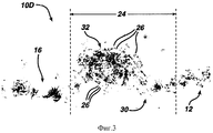
Фиг. 3 представляет собой микрофотографию сечения по линии 2A-2A на фиг. 2. FIG. 3 is a micrograph of a section taken along
Фиг. 4 представляет собой микрофотографию сечения по линии 4-4 на фиг. 2. FIG. 4 is a micrograph of a section taken along line 4-4 of FIG. 2.
Фиг. 5 представляет собой сечение, при значительном увеличении, одного из типов приподнятых участков нетканого полотна в соответствии с настоящим изобретением. FIG. 5 is a cross section, with a significant increase, of one type of raised portion of a nonwoven fabric in accordance with the present invention.
Фиг. 6 представляет собой микрофотографию второго типа приподнятого участка нетканого полотна в соответствии с настоящим изобретением. FIG. 6 is a micrograph of a second type of elevated portion of a nonwoven fabric in accordance with the present invention.
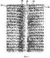
Фиг. 7 представляет собой микрофотографию сечения по линии 7-7 на фиг. 6. FIG. 7 is a micrograph of a section taken along line 7-7 of FIG. 6.
Фиг. 8 представляет собой идеализированный эскиз сечения, приведенного на фиг. 7. FIG. 8 is an idealized sketch of the section of FIG. 7.
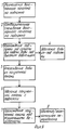
На фиг. 9 приведена блок-схема стадий процесса изготовления нетканого полотна по настоящему изобретению. In FIG. 9 is a flow chart of the steps for manufacturing a nonwoven fabric of the present invention.
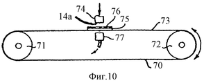
На фиг. 10, 11 и 12 схематично приведены три типа устройств для получения нетканого полотна по настоящему изобретению. In FIG. 10, 11 and 12 schematically illustrate three types of devices for producing the nonwoven fabric of the present invention.
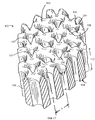
На фиг. 13 дан изометрический вид с частичным разрезом участка подложки со сформированной текстурированной структурой, которая (подложка) используется для получения фонового участка нетканого полотна по настоящему изобретению. In FIG. 13 is a partially cutaway isometric view of a portion of a substrate with a formed textured structure that (substrate) is used to produce a background portion of the nonwoven fabric of the present invention.
Фиг. 14A представляет собой эскиз сечения, на котором показан один из типов углубленного участка подложки со сформированной текстурированной структурой, которая (подложка) может использоваться для получения нетканого полотна в соответствии с настоящим изобретением. FIG. 14A is a sectional sketch showing one type of recessed portion of a substrate with a formed textured structure that (substrate) can be used to produce a nonwoven fabric in accordance with the present invention.
Фиг. 14B представляет собой эскиз сечения, на котором показан другой тип углубленного участка подложки со сформированной текстурированной структурой, которая (подложка) может использоваться для получения нетканого полотна в соответствии с настоящим изобретением. FIG. 14B is a sectional sketch showing another type of recessed portion of a substrate with a formed textured structure that (the substrate) can be used to produce a nonwoven fabric in accordance with the present invention.
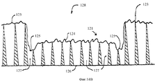
Фиг. 15 представляет собой эскиз сечения нетканого полотна, изготовленного с использованием подложки по фиг. 14B. FIG. 15 is a cross-sectional sketch of a nonwoven fabric made using the substrate of FIG. 14B.
На фиг. 16 схематично представлено устройство для изготовления подложек с текстурированной структурой, которые могут использоваться для изготовления нетканого полотна в соответствии с настоящим изобретением. In FIG. 16 is a schematic illustration of a device for manufacturing substrates with a textured structure that can be used to make a nonwoven fabric in accordance with the present invention.
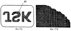
Фиг. 17a представляет собой карту шаблона для подложки, используемой в производстве нетканого полотна 10C на фиг. 1C. FIG. 17a is a template card for a substrate used in the manufacture of nonwoven fabric 10C in FIG. 1C.
Фиг. 17b представляет собой карту шаблона при значительном увеличении для прямоугольного участка на фиг. 17a. FIG. 17b is a map of the template at a significant magnification for the rectangular portion in FIG. 17a.
Если теперь обратиться к чертежам, то на фиг. 1A приведен вид сверху варианта осуществления нетканого полотна по настоящему изобретению. Нетканое полотно 10A включает фоновый участок 12 и по меньшей мере один сформированный за одно целое приподнятый участок 16. Три подобных приподнятых участка, обозначенных буквами J, S и K, представлены на фиг. 1A. Нетканое полотно 10 включает множество волокон штапельной длины, которые могут быть, например, из хлопка, искусственного шелка или полиэфира или из их смеси. Фоновый участок 12 расположен в первой плоскости нетканого полотна 10A и определяет ее. Приподнятые участки 16 размещаются в плоскости, расположенной выше и параллельно первой плоскости. Приподнятые участки 16 соединяются с фоновой частью 12 посредством переходной области, образованной волокнами, которая будет более подробно рассмотрена далее. В нетканом полотне 10A, приведенном на фиг. 1A, базовый вес приподнятых участков 16 тот же, что и базовый вес фонового участка 12. Плотность приподнятого участка 16 практически идентична плотности фонового участка 12. Turning now to the drawings, in FIG. 1A is a plan view of an embodiment of a nonwoven fabric of the present invention. The nonwoven fabric 10A includes a
Что касается фиг. 1B, то он поясняет второй вариант нетканого полотна по настоящему изобретению. Нетканое полотно 10B также получают из множества штапельной длины волокон, и оно имеет фоновый участок 12 и сформированный за одно целое приподнятый участок 18, который, если смотреть на него сверху, обычно имеет прямоугольную форму. Как и в случае нетканого полотна 10A, фоновый участок 12 нетканого полотна 10B расположен в первой плоскости нетканого полотна 10A и определяет ее. Как и в случае нетканого полотна 10A, приподнятый участок 18 нетканого полотна 10B соединяется со своей фоновой поверхностью 12 посредством переходной области, образованной волокнами, которая, как указано выше, будет более подробно рассмотрена далее. Базовый вес приподнятого участка 18 в нетканом полотне 10B больше, чем базовый вес фонового участка 18, с которым он соединяется. Таким образом, в то время как приподнятые участки 16 в составе нетканого полотна 10A имеют тот же базовый вес, что и его фоновый участок 12, базовый вес приподнятого участка 18 нетканого полотна 10B отличен от базового веса фонового участка 12. With reference to FIG. 1B, he explains a second embodiment of the nonwoven fabric of the present invention. The nonwoven fabric 10B is also obtained from a plurality of staple lengths of fibers, and it has a
Вид сверху третьего варианта нетканого полотна по настоящему изобретению представлен на фиг. 1C. Как и в случае нетканого полотна 10A и 10B, нетканое полотно 10C изготовлено из множества волокон штапельной длины. Нетканое полотно 10C включает фоновый участок 12, который расположен в первой плоскости нетканого полотна и определяет ее, так что в этом отношении он сходен с другими типами нетканого полотна по настоящему изобретению. Нетканое полотно 10C включает первый приподнятый участок 16, обозначенный буквами J, S и K на фиг. 1C. Нетканое полотно 10C далее содержит приподнятый участок 18, включающий указанные буквы J, S и K. Приподнятый участок 18 нетканого полотна 10C соответствует приподнятому участку 16 нетканого полотна 10A. Приподнятый участок 18 нетканого полотна 10C соответствует приподнятому участку 18 нетканого полотна 10B. Следует понимать, что приподнятый участок 16 нетканого полотна 10C имеет базовый вес, который практически идентичен базовому весу фонового участка ткани. С другой стороны, приподнятый участок 18, входящий в состав нетканого полотна 10C, имеет больший базовый вес, чем базовый вес его фонового участка 12. Плотности фонового участка 12, первого приподнятого участка 16 и второго приподнятого участка 18 нетканого полотна 10C практически идентичны. A top view of a third embodiment of the nonwoven fabric of the present invention is shown in FIG. 1C. As with the nonwoven fabric 10A and 10B, the nonwoven fabric 10C is made of a plurality of staple length fibers. The nonwoven fabric 10C includes a
Фоновые участки 12 нетканого полотна 10A, 10B и 10C одинаковы в каждом случае. Этот фоновый участок имеет внешний вид и узор, напоминающиe трикотаж, однако следует понимать, что фоновый участок может иметь разный узор и внешний вид. В конкретном случае нетканого полотна 10A приподнятые участки 16 и фоновый участок 12 имеют тот же узор и внешний вид, напоминающиe трикотаж. Аналогично приподнятый участок 18 нетканого полотна 10B также имеет внешний вид, напоминающий трикотаж, что и фоновый участок 12. Наконец, фоновый участок 12, первый приподнятый участок 16 и второй приподнятый участок 18, составляющие нетканое полотно 10C, все имеют тот же узор и внешний вид, напоминающиe трикотаж. Однако следует понимать, что первый приподнятый участок, второй приподнятый участок 18 и фоновый участок 12 нетканого полотна 10C могут иметь разные узоры и внешний вид. The
На фиг. 2 представлена микрофотография при увеличении в 15 раз фрагмента нетканого полотна 10D, который аналогичен нетканому полотну 10A, изображенному на фиг. 1A. Нетканое полотно 10D включает фоновый участок 12, напоминающий по внешнему виду трикотаж, и приподнятый участок 16, который также имеет узор, напоминающий трикотаж. Следует понимать, что на фиг. 2, представлен лишь фрагмент приподнятого участка 16. Приподнятый участок 16 соединяется с фоновым участком 12 посредством переходных областей 22 и 24. Как видно из фиг. 2, образованная волокнами переходная область простирается в горизонтальном направлении по одной стороне приподнятого участка 16, при этом горизонтальное направление пересекает машинное направление в нетканом полотне 10D. Образованная волокнами переходная область 24 простирается в продольном направлении по другой стороне рельефного участка 16, при этом указанное продольное направление совпадает с машинным направлением в нетканом полотне 10D. Образованная волокнами переходная область 22 пересекает образованную волокнами переходную область 24 под углом приблизительно 90o на конце 23 приподнятого участка 16. Структуры волокон переходных областей 22 и 24 практически одинаковы. Как указано ранее, базовый вес приподнятого участка 16 практически тот же, что и базовый вес фонового участка 12.In FIG. 2 is a photomicrograph with a 15-fold increase in a fragment of
На фиг. 2A приведен эскиз нетканого полотна 10D, микрофотография поверхности которого представлена на фиг. 2. Фиг. 2A, которая приведена для того, чтобы можно было лучше понять структуру волокон нетканого полотна 10D, представляет собой изометрический вид сечения по линии 2A-2A на фиг. 2. Если обратиться к фиг. 2A, то можно увидеть, что нетканое полотно 10D имеет образованный волокнами фоновый участок 12 и образованный волокнами приподнятый участок 16, каждый из которых сформирован в виде узора, напоминающего трикотаж. Приподнятый участок 16 соединяется с фоновым участком 12 посредством переходной области 24, образованной волокнами, которая простирается в машинном направлении полотна 10D. Образованная волокнами переходная область 24 включает обедненный волокнами участок 30 и обогащенный волокнами участок 32. Обедненный волокнами участок 30 включает множество пучков 30a, образованных сегментами волокон, и эти пучки 30a определяют множество отверстий 30b в переходной области 24. Сегменты волокон, составляющие пучки 30a, располагаются строго параллельно, и некоторые из этих сегментов волокон свернуты внутри пучка. Большинство пучков 30a скручены и свернуты вокруг себя. In FIG. 2A is a sketch of a
Обогащенный волокнами участок 32 включает множество сегментов волокон, которые простираются преимущественно в вертикальном направлении на фиг. 2, которое соответствует машинному направлению в нетканом полотне 10D. Концы указанных сегментов волокон можно увидеть на фиг. 2A, где они обозначены цифрами 26. Базовый вес обедненного волокнами участка 30 меньше, чем базовый вес обогащенного волокнами участка 32, а также меньше, чем базовый вес как фонового участка 12, так и приподнятого участка 16. Базовый вес обогащенного волокнами участка 32 больше, чем базовый вес как фонового участка 12, так и приподнятого участка 16. Пучки 30a в обедненном волокнами участке 30 ориентированы главным образом поперечно по отношению к образованной волокнами переходной области 24. Сегменты волокон, составляющие обогащенный волокнами участок 32, ориентированы главным образом продольно по отношению к переходной области 24. The fiber-enriched
Фиг. 2B представляет собой другой эскиз нетканого полотна 10D. На фиг. 2B приведен изометрический вид разреза по линии 4-4 на фиг. 2. Если обратиться к фиг. 2B, то приподнятая часть 16 соединяется с фоновым участком 12 посредством переходной области 22, образованной волокнами, которая простирается в направлении, поперечном направлению волокон 10D. Переходная область 22 включает обедненный волокнами участок 27 и обогащенный волокнами участок 28, аналогичные соответственно обедненному волокнами участку 30 и обогащенному волокнами участку 32 переходной области 24, образованной волокнами, которая рассмотрена ранее. Обедненный волокнами участок 27 включает множество пучков 27a, образованных сегментами волокон, и эти пучки 27a определяют множество отверстий 27b в переходной области 22. Сегменты волокон, составляющие пучки 27a, располагаются строго параллельно, и некоторые из этих сегментов волокон свернуты внутри пучка. Меньшая часть пучков 27a скрученa и свернутa вокруг себя. Рассмотренная структура контрастирует со структурой обедненных волокнами участков 30 рассмотренной ранее переходной области 24, в которой большинство пучков 30a скрученo и свернутo вокруг себя. Обогащенный волокнами участок 28 включает множество сегментов волокон, которые простираются преимущественно в горизонтальном направлении на фиг. 2, которое соответствует направлению, пересекающему машинное направление в нетканом полотне 10D. Концы указанных сегментов волокон можно увидеть на фиг. 2A, где они обозначены цифрами 29. Базовый вес обедненного волокнами участка 27 меньше, чем базовый вес обогащенного волокнами участка 28, а также меньше, чем базовый вес как фонового участка 12, так и приподнятого участка 16. Базовый вес обогащенного волокнами участка 28 больше, чем базовый вес как фонового участка 12, так и приподнятого участка 16. Пучки 27a в обедненном волокнами участке 27 ориентированы главным образом поперечно по отношению к образованной волокнами переходной области 22. Сегменты волокон, составляющие обогащенный волокнами участок 28, ориентированы главным образом продольно по отношению к переходной области 22. FIG. 2B is another sketch of a
Фиг. 3 представляет собой микрофотографию нетканого полотна 10D по линии 2A-2A на фиг. 2. На фиг. 3 виден приподнятый участок 16, соединенный с фоновым участком 12 посредством переходной области 24. Как видно из фотографии, обогащенный волокнами участок 32 примыкает к обедненному волокнами участку 30. Большое количество концов волокон 26 в обогащенном волокнами участке 32 свидетельствует о высокой параллельности сегментов волокон в обогащенном волокнами участке. FIG. 3 is a micrograph of
Фиг. 4 представляет собой микрофотографию образованной волокнами переходной области 22 нетканого полотна 10D по линии 4-4 на фиг. 2. Число 28 обозначает обогащенный волокнами участок переходной области 22, в то время как число 27 обозначает обедненный волокнами участок. Видно, что сегменты волокон в обедненном волокнами участке 27 расположены практически параллельно. В общем случае волокна в обогащенном волокнами участке 28 менее параллельны, чем в соответствующем участке 32, показанном на фиг. 3. FIG. 4 is a micrograph of the fiber-formed
На фиг. 5 в художественном виде представлено сечение, на котором показано, как приподнятый участок 16 соединяется с фоновым участком посредством переходной области 24. Переходная область 24 включает обедненный волокнами участок 30 и обогащенный волокнами участок 32. Как указывалось ранее, обогащенный волокнами участок 32 имеет больший базовый вес, чем обедненный волокнами участок 30. Базовый вес приподнятого участка, лежащего между обогащенным волокнами участком 32 на фиг. 5, практически однороден и практически совпадает с базовым весом фонового участка 12. In FIG. 5 is an artistic sectional view showing how the raised
На фиг. 6 в виде микрофотографии приведен увеличенный фрагмент нетканого полотна, аналогичного нетканому полотну 10B по фиг. 1B. Фоновый участок 12 с обеих сторон от приподнятого участка 18 имеет узор, напоминающий трикотажный. В этом варианте осуществления изобретения узор, напоминающий трикотажный, присутствует и на верхней поверхности приподнятого участка 18. Волокна, составляющие приподнятый участок 18, собраны в пучки, которые свернуты и скручены друг с другом и в значительной степени параллельны друг другу в продольном направлении приподнятого участка. In FIG. 6 is an enlarged fragment of a nonwoven fabric similar to the nonwoven fabric 10B of FIG. 1B. The
Как указывалось ранее в настоящем описании, базовый вес приподнятого участка 18 больше, чем базовый вес фонового участка 12. As indicated earlier in the present description, the base weight of the raised
Плотность приподнятого участка 18 практически совпадает с плотностью фонового участка. Приподнятый участок 18 соединяется с фоновым участком 12 посредством образованной волокнами переходной области 34, которая имеет меньший базовый вес, чем базовый вес фонового участка 12. The density of the
Фиг. 7 представляет собой микрофотографию сечения нетканого полотна по линии 7-7 на фиг. 6. Большое количество концов волокон 36 в приподнятом участке 18 свидетельствует о том, что сегменты волокон в приподнятом участке простираются в продольном направлении приподнятого участка. FIG. 7 is a micrograph of a section of a nonwoven fabric taken along line 7-7 of FIG. 6. The large number of fiber ends 36 in the raised
На фиг. 8 в художественном виде представлено сечение, на котором показано, как приподнятый участок 18 соединяется с фоновым участком посредством переходной области 34. Как видно из рисунка, нижняя поверхность 18a приподнятого участка 18 в значительной степени компланарна нижней поверхности 12a фонового участка 12. Крайняя верхняя поверхность 18в приподнятого участка 18 расположена над верхней поверхностью 12в фонового участка. In FIG. 8 is an artistic sectional view showing how the raised
Фиг. 9 представляет собой блок-схему, на которой показаны различные стадии процесса получения нового нетканого полотна по настоящему изобретению. Первый стадией указанного процесса является размещение волоконного полотна на топографической подложке (подложке со сформированной текстурированной структурой) (блок 1). Волоконное полотно предварительно увлажняют или промачивают, когда оно уже находится на этой подложке (блок 2), для того чтобы оно не смещалось с подложки в процессе обработки. Подложка с находящимся на ней волоконным полотном проходит под соплами, из каждого из которых под большим давлением подается жидкость, такая как вода, и направляется на верхнюю поверхность волоконного полотна, т.е. на поверхность волоконного полотна, которая не контактирует с имеющей текстурированную структуру подложкой (блок 3). Предпочтительной жидкостью является вода. Вода отводится от подложки преимущественно с использованием вакуума (блок 4). Волоконное полотно обезвоживается (блок 5). Обезвоженное сформированное полотно удаляется с подложки (блок 6). Сформированное полотно далее проходит серию сушильных барабанов, чтобы ткань высохла (блок 7). Затем ткань проходит финишную обработку или подвергается, если необходимо, дальнейшей переработке (блок 8). FIG. 9 is a flowchart showing various stages of the process for producing the new nonwoven fabric of the present invention. The first stage of this process is the placement of the fiber web on a topographic substrate (a substrate with a formed textured structure) (block 1). The fiber web is pre-moistened or soaked when it is already on this substrate (block 2), so that it does not move from the substrate during processing. The substrate with the fiber web located thereon passes under the nozzles, from each of which a liquid, such as water, is supplied under high pressure and is directed to the upper surface of the fiber web, i.e. on the surface of the fiber web, which is not in contact with the substrate having a textured structure (block 3). The preferred liquid is water. Water is removed from the substrate mainly using vacuum (block 4). The fiber web is dehydrated (block 5). The dehydrated formed web is removed from the substrate (block 6). The formed web then passes through a series of drying drums to dry the fabric (block 7). Then the fabric goes through finishing or undergoes further processing, if necessary (block 8).
На фиг. 10 схематично представлен один из типов устройств для осуществления процесса и получения тканей по настоящему изобретению. В указанном устройстве дырчатый ремень 70 конвейера постоянно движется между двумя пространственно разделенными вращающимися валками 71 и 72. Ремень приводится в движение таким образом, что направление его движения может быть изменено на противоположное, т. е. он может перемещаться как по часовой, так и против часовой стрелки. Над верхним участком 73 ремня располагается соответствующий коллектор 74, откуда подается вода. Этот коллектор содержит множество отверстий или щелей с очень маленьким диаметром. Диаметр отверстий составляет приблизительно 0,007 дюйма (0,178 мм) в диаметре, а количество отверстий составляет приблизительно 30 на линейный дюйм. Вода под давлением подается в коллектор 74 и инжектируется из отверстий в форме практически столбчатых не отклоняющихся струй или потоков. На ремне 70 располагается подложка 75 со сформированной текстурированной структурой, а на указанной подложке со сформированной текстурированной структурой размещается волоконное полотно 76. Непосредственно под водяным коллектором 74, теперь уже под нижним участком 73 ремня 70, располагается коллектор для отсасывания 77. Этот коллектор для отсасывания помогает удалять воду, инжектируемую из коллектора 74, и предотвращает переполнение волоконного полотна 76 водой. Вода, поступающая к коллектору под определенным давлением, инжектируется через отверстия из коллектора в виде практически столбчатых струй или потоков и ударяется о верхнюю поверхность волоконного полотна 76. Расстояние между нижней поверхностью 74a коллектора 74 и верхней поверхностью полотна 76, подвергаемого обработке, чрезвычайно мало, так чтобы струи воды, выходящие из отверстий коллектора 74, вступали в контакт с верхней поверхностью волоконного полотна 76 в указанной выше практически столбчатой, не расходящейся форме. Это расстояние может изменяться, однако обычно составляет приблизительно 0,75 дюйма (19,05 мм). Струи воды проходят через волоконное полотно, затем через дренажные отверстия, сделанные в подложке со сформированной текстурированной структурой. Использованная вода удаляется коллектором для отсасывания. Очевидно, что подложка со сформированной текстурированной структурой с расположенным на ней волоконным полотном может проходить под коллектором, если необходимо, несколько раз, так чтобы получилась ткань по настоящему изобретению. In FIG. 10 schematically illustrates one type of device for carrying out the process and for producing the tissues of the present invention. In the specified device, the
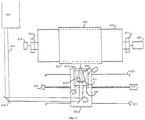
На фиг. 11 приведено устройство для осуществления непрерывного процесса производства тканей по настоящему изобретению. Устройство на фиг. 11 включает ремень 80 конвейера, который в соответствии с настоящим изобретением и является подложкой со сформированной текстурированной структурой. Ремень непрерывно движется против часовой стрелки вокруг пространственно разделенных вращающихся валков, что хорошо известно из данной области техники. Над ремнем 80 расположен коллектор 79 для подачи жидкости, соединяющий множество линий или групп 81 отверстий. Каждая группа включает по меньшей мере один ряд или большее количество рядов отверстий с очень маленьким диаметром (диаметр каждого отверстия составляет приблизительно 0,007 дюйма (0,1178 мм), при этом количество указанных отверстий составляет тридцать на дюйм. Вода поступает к группам 81 отверстий под заданным давлением и инжектируется из отверстий в форме очень тонких, практически столбчатых, не расходящихся потоков или струй воды. Коллектор снабжен манометрами 88 и управляющими вентилями 87 для регулирования давления жидкости в каждой линии или группе отверстий. Под каждой линией или группой отверстий располагается отсасывающее устройство 82 для удаления избытка воды и предотвращения захлебывания рабочей зоны. Волоконное полотно 83, которое превращают в ткань по настоящему изобретению, поступает на подложку со сформированной текстурированной структурой на ленте конвейера. Через соответствующее сопло 84 на волоконное полотно подается вода с целью его предварительного смачивания и облегчения контроля за волокнами по мере их прохождения под коллекторами, инжектирующими воду. Под указанным соплом для подачи воды размещается канал 85 для отсасывания, удаляющий избыточную воду. Волоконное полотно проходит под подающим жидкость коллектором против часовой стрелки. Давление, поданное на любую выбранную группу 81 отверстий, может быть задано независимо от давления, поданного на любую другую группу 81 отверстий. Обычно на группу 81 отверстий ближайшего сопла 84 подается сравнительно низкое давление, в частности 100 фунтов на квадратный дюйм (689,6 кПа). Это способствует размещению поступающего полотна на поверхности подложки. По мере того как полотно продвигается против часовой стрелки, как это показано на фиг. 11, давление, которое подается на группы 81 отверстий, обычно возрастает. Необходимо, чтобы каждая последующая группа 81 отверстий функционировала под давлением, большим, чем соседняя группа в направлении по часовой стрелке. Например, на две или большее количество групп 81 отверстий может быть подано одинаковое давление, а следующая группа 81 отверстий (в направлении против часовой стрелки) может функционировать под другим давлением. Как правило, рабочее давление на конце ремня конвейера, откуда полотно удаляется, выше, чем рабочее давление в том месте, где полотно первоначально поступает на ремень конвейера. Хотя на фиг. 11 показано шесть групп 81 отверстий, это количество не является критическим, а определяется весом полотна, скоростью выполнения операции, применяемым давлением воды, количеством рядов отверстий в каждой группе и т.п. После прохождения между коллектором для подачи и коллектором для отсасывания воды полученная ткань проходит над дополнительным каналом 86 для удаления из нее избытка воды. Типичное расстояние от нижней поверхности групп 81 отверстий до верхней поверхности волоконного полотна 83 лежит в интервале приблизительно от 0,5 дюймов (12,7 мм) до приблизительно 2,0 дюймов (50,8 мм); предпочтительным является интервал приблизительно от 0,75 дюймов (19,05 мм) до приблизительно 1,0 дюйма (25,4 мм). Очевидно, что полотно не может быть размещено настолько близко к коллектору, что полотно будет касаться коллектора. С другой стороны, если расстояние между нижней поверхностью отверстий и верхней поверхностью полотна будет слишком большим, то потоки жидкости потеряют свою энергию и процесс будет не столь эффективным. In FIG. 11 shows a device for implementing a continuous fabric production process of the present invention. The device of FIG. 11 includes a
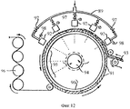
Предпочтительное устройство для изготовления тканей в соответствии с настоящим изобретением схематично представлено на фиг. 12. В указанном устройстве подложкой со сформированной текстурированной структурой является вращающийся барабан 90. Барабан вращается против часовой стрелки. Барабан 90 может иметь форму вытянутого цилиндра и может быть изготовлен из множества волнистых пластинок 91, расположенных таким образом, что они образуют внешнюю поверхность барабана. В любом случае внешняя поверхность барабана 90 или внешняя поверхность волнистых пластинок 91 образует нужную конфигурацию текстурированной структуры подложки. Над периферийной частью барабана размещается коллектор 89, соединяющий множество планок 92 с форсунками для подачи воды или другой жидкости к волоконному полотну 93, которое размещено на внешней поверхности волнистых пластинок. Каждая планка с форсунками может включать ряд или несколько рядов отверстий с очень маленьким диаметром или щелей, которые уже упоминались ранее. Как правило, отверстия имеют диаметр приблизительно от 0,005 дюйма (0,127 мм) до 0,010 дюйма (0,254 мм). Если необходимо, то количество отверстий может составлять от 50 до 60 отверстий на дюйм или более. Через ряды отверстий подается вода или другая жидкость. В общем случае, как уже пояснялось ранее, давление в каждой группе отверстий повышается от первой группы, под которой проходит волоконное полотно, до последней группы. Давление контролируется соответствующими вентилями управления давлением 97, при этом величина давления регистрируется манометрами 98. Барабан соединен с отстойником 94, к которому может прилагаться вакуум, чтобы облегчить удаление воды и предотвратить захлебывание рабочей зоны. В процессе производства волоконное полотно 93, прежде чем оно пройдет под коллектором 89 для подачи воды, помещается на верхнюю часть подложки со сформированной текстурированной структурой, как это показано на фиг. 12. Волоконное полотно проходит под планками с отверстиями и превращается в нетканое полотно по настоящему изобретению. Полученная ткань затем проходит над секцией 95 устройства, где нет планок с отверстиями, однако вакуум продолжают прикладывать. Ткань после удаления воды снимают с барабана и пропускают через серию сушильных барабанов 96 для окончательной сушки полотна. A preferred fabric manufacturing apparatus in accordance with the present invention is shown schematically in FIG. 12. In the specified device, the substrate with the formed textured structure is a rotating drum 90. The drum rotates counterclockwise. The drum 90 may be in the form of an elongated cylinder and may be made of a plurality of
Чтобы сформировать рельефные участки в нетканом полотне по настоящему изобретению, слой волокон или слегка спутанного волокна помещается на дырчатую подложку, верхняя поверхность которой имеет сформированную текстурированную структуру и вторую поверхность, смещенную относительно верхней поверхности подложки. Верхняя поверхность формирует фоновый участок ткани, а вторая поверхность формирует приподнятый участок ткани. In order to form the embossed areas in the nonwoven fabric of the present invention, a layer of fibers or a slightly tangled fiber is placed on a holey substrate, the upper surface of which has a formed textured structure and a second surface that is offset from the upper surface of the substrate. The upper surface forms the background tissue site, and the second surface forms the elevated tissue site.
Верхняя поверхность имеет структуру, которая снижает до минимума латеральное перемещение волокон исходного волоконного полотна, которое могло бы привести к формированию нежелательных областей с высокой и низкой концентрацией волокон. Если будет наблюдаться чрезмерное латеральное движение волокон в процессе изготовления ткани, то полученное нетканое волокно может содержать тонкие места или участки, где нет волокон. The upper surface has a structure that minimizes lateral movement of the fibers of the original fiber web, which could lead to the formation of undesirable areas with high and low fiber concentrations. If excessive lateral movement of the fibers is observed during fabric manufacturing, the resulting non-woven fiber may contain thin spots or areas where there are no fibers.
Пример подложки со сформированной текстурированной структурой для формирования рисунка в фоновом участке нетканого полотна приведен на фиг. 13. Подложка 102 включает корпус 100, имеющий верхнюю поверхность 103 и нижнюю поверхность 104. На всей поверхности 103 в виде определенного рисунка располагается матрица, образованная пиками 105, разделенными впадинами 106. В виде определенного рисунка в толще подложки 102 располагается множество дренажных отверстий 107. В данном варианте осуществления изобретения каждое дренажное отверстие 107 окружено скоплением из шести пиков 105 и шести впадин 106. An example of a substrate with a formed textured structure for forming a pattern in the background portion of a nonwoven fabric is shown in FIG. 13. The substrate 102 includes a
Дренажные отверстия 107 имеют коническую форму или форму "патрубка с широким устьем" с большим диаметром на верхней поверхности 103 подложки, чем на нижней поверхности 104. The drainage holes 107 have a conical shape or a "wide-mouth pipe" shape with a larger diameter on the
Чтобы добиться желаемого результата, необходимо контролировать угол 111, образованный конусом, по отношению к толщине 112 подложки 102. Например, если угол слишком велик, то отверстие будет слишком маленьким и дренаж будет недостаточен. Если угол слишком мал, то на подложке будет образовано очень мало пиков или впадин или же они вовсе не образуются. To achieve the desired result, it is necessary to control the angle 111 formed by the cone with respect to the
Немаловажное значение также имеет расстояние между центрами, S, соседних отверстий в повторяющемся узоре. Пики 105 и впадины 106 образованы пересечением конусообразных отверстий 107. Если расстояние между центрами отверстий S больше, чем наибольший диаметр отверстия 107 на верхней поверхности 103, пересечение не наблюдается и получается подложка с гладкой плоской поверхностью с находящимися на ней коническими отверстиями. Если расстояние между центрами соседних отверстий меньше, чем диаметр отверстия, измеренный вдоль линии, соединяющей эти центры, то поверхности конусов пересекаются, образуя впадину. Подложка, показанная на фиг. 13, будет формировать узор, похожий на трикотажный, на фоновом участке нетканого полотна по настоящему изобретению. Однако, чтобы сформировать фоновый участок нетканого полотна, можно использовать любую матрицу. Equally important is the distance between the centers, S, of the neighboring holes in the repeating pattern.
Вторая поверхность дырчатой подложки включает множество углублений, которые формируют приподнятый участок полученной ткани. Фиг. 14A представляет собой сечение подложки 122, имеющей верхнюю поверхность 123 и углубленный участок 121, образующий вторую поверхность 124. Отверстия 127 направлены приблизительно по нормали к поверхности подложки и продолжаются от верхней поверхности 103 до нижней поверхности 104. Отверстия должны иметь соответствующий размер и количество, чтобы удалять избыток жидкости в процессе спутывания волокон и предотвращать "захлебывание" подложки в процессе производства. The second surface of the perforated substrate includes many recesses that form a raised portion of the resulting fabric. FIG. 14A is a cross-section of a
Для специалистов является очевидным, что углубленный участок 121 должен иметь достаточный размер, чтобы сформировать четко выраженный приподнятый участок в конечном нетканом полотне. Например, конкретная подложка 102, приведенная на фиг. 13, имеет повторяющуюся матрицу, образованную одним отверстием 107, окруженным шестью пиками 105. Расстояние между центрами отверстий 107 в подложке 102 равно S. Наименьший линейный размер углубленного участка 121 должен быть больше, чем расстояние S между центрами. Если наиболее узкая часть углубленного участка 121 меньше, чем расстояние S, то приподнятый участок в конечном нетканом полотне не будет четко сформирован или же вообще не образуется. В конкретном варианте подложки 122, которая используется для изготовления нетканого полотна по настоящему изобретению, ширина углубленного участка 121 приблизительно в 11 раз больше, чем расстояние S между центрами отверстий 107. Углубленные поверхности должны иметь достаточную глубину, чтобы их можно было выделить как отдельный уровень, и могут быть как искривленными, так и плоскими. Вторая углубленная поверхность 121 участка 122 может иметь тот же самый узор, что и верхняя поверхность 123, или же иметь отличный узор. It is obvious to those skilled in the art that the recessed
Верхняя поверхность подложки обладает текстурой, подходящей для того, чтобы контролировать перемещение волокон, препятствуя "вымыванию" отдельных участков, однако обеспечивая полотну достаточную мобильность, с тем чтобы волокна могли самоорганизовываться, образуя углубления и сцепляясь друг с другом под действием струй жидкости. Если используется достаточно развитая матрица из отверстий, то дополнительная текстура не потребуется. Обычно, тем не менее, на указанной поверхности формируется дополнительная текстура, чтобы лучше контролировать перемещение волокон и придать полученной ткани большую привлекательность. The upper surface of the substrate has a texture suitable to control the movement of fibers, preventing the "washing out" of individual sections, but providing the canvas with sufficient mobility so that the fibers can self-organize, forming depressions and adhere to each other under the influence of liquid jets. If a sufficiently developed matrix of holes is used, then an additional texture is not required. Usually, however, an additional texture is formed on the indicated surface in order to better control the movement of the fibers and make the resulting fabric more attractive.
Между двумя уровнями можно различить переходную область. Происходит уменьшение концентрации волокон на краю фоновых участков и соответствующее увеличение концентрации волокон вблизи края приподнятого участка. Из образца ткани со средним весом 2,19 унции на квадратный ярд (76,39 г/м2) нарезают полоски шириной 7/64 дюйма (2,778 мм) и длиной 1/2 дюйма (12,7 мм), при этом длинный размер параллелен переходной линии, расположенной в области наибольшей и наименьшей концентрации волокон. Отношение веса тяжелых полосок к весу легких полосок для четырех типов различных узоров составляет в среднем 1,53: 1. В результате устанавливают, что базовый вес фонового участка широкого элемента приблизительно равен базовому весу приподнятого участка, однако это недостаточно характеризует переходную область с легкими и тяжелыми участками. Чтобы исправить эту ситуацию для больших элементов в предпочтительном варианте ткани по настоящему изобретению, должно быть три или более различимых практически параллельных плоскостей, каждая из которых располагалась бы на разном уровне на подложке.A transition region can be distinguished between the two levels. There is a decrease in the concentration of fibers at the edge of the background sections and a corresponding increase in the concentration of fibers near the edge of the raised section. From a fabric sample with an average weight of 2.19 ounces per square yard (76.39 g / m 2 ), strips 7/64 inch (2.778 mm) wide and 1/2 inch (12.7 mm) long are cut, with a long size parallel to the transition line located in the region of the highest and lowest fiber concentration. The ratio of the weight of heavy strips to the weight of light strips for four types of different patterns is on average 1.53: 1. As a result, it is established that the base weight of the background portion of the wide element is approximately equal to the base weight of the raised portion, however this does not sufficiently characterize the transition region with light and heavy plots. To remedy this situation for large elements in a preferred embodiment of the fabric of the present invention, there should be three or more distinguishable almost parallel planes, each of which would be located at a different level on the substrate.
На фиг. 14B показан разрез подложки 128 со сформированной текстурированной структурой, которая (подложка) имеет верхнюю поверхность 123, углубленный участок 121, поверхность 124 углубленного участка, второй углубленный участок 125 и нижнюю поверхность 126. Отверстия 127 пронизывают подложку на всю ее толщину. In FIG. 14B shows a section through a
Нетканое волокно, получаемое с использованием подложки 122, имеет фоновый участок 12, приподнятый участок 16 и переходную область 24, образованную обедненным волокнами участком 30 и обогащенным волокнами участком 32. Обогащенный волокнами участок 32 переходной области 24 примыкает к периферии приподнятого участка 16 и связан с ним. В этом варианте ткани по изобретению наблюдается четкая и визуально наблюдаемая граница между обедненным волокнами участком 30 и фоновым участком 12. Однако граница между обогащенным волокнами участком 32 и периферией приподнятого участка 16 менее выраженная и не столь заметна для глаза. Эту последнюю границу можно сделать более отчетливой и заметной для глаза, если использовать для получения нетканого полотна подложку со сформированной текстурированной структурой, приведенную на фиг. 14B. Как видно из фиг. 14B, подложка 128 со сформированной текстурированной структурой имеет верхнюю поверхность 123, углубленную поверхность 124, пару вторых углубленных участков 125, нижнюю поверхность 126 и множество отверстий 127, пронизывающих подложку на всю ее толщину. Нетканое полотно, полученное с использованием подложки со сформированной текстурированной структурой 128, показано в разрезе на фиг. 15. Как видно из рисунка, нетканое полотно имеет фоновый участок 12, приподнятый участок 16 и образованную волокнами переходную область 24, которая соединяет фоновый участок и приподнятый участок. Переходная область 24 включает обедненный волокнами участок 30 и обогащенный волокнами участок 32, аналогичный участкам, изображенным на фиг. 5. В то время как в нетканом полотне по фиг. 5 верхняя поверхность обогащенного волокнами участка 32 практически компланарна верхней поверхности приподнятого участка 16, верхняя поверхность аналогичного обогащенного участка 32 в нетканом полотне, приведенном на фиг. 15, располагается в плоскости, которая находится над плоскостью верхней поверхности приподнятого участка 16. Это является результатом того, что в подложке 128 имеется пара вторых углубленных участков 125. В нетканом полотне по фиг. 15 граница между обогащенным волокнами участком 32 пограничной области 24 и приподнятым участком 16 более отчетлива и визуально лучше различима, чем в случае нетканого полотна по фиг. 5. Дополнительные углубленные участки в подложке способствуют формированию дополнительных приподнятых участков в ткани. Если необходимо сформировать дополнительные соответствующие приподнятые участки в нетканом полотне, то в подложке можно сформировать множество углубленных поверхностей. Очевидно, что в соответствии с описанием настоящего изобретения можно использовать подложку, которая позволяет получить модифицированное нетканое полотно, приведенное на фиг. 15, в котором центральная область приподнятого участка 16 содержит дополнительный приподнятый участок, который выступает вверх от верхней поверхности указанного приподнятого участка. The nonwoven fiber obtained using the
Если вновь вернуться к фиг. 1B, то можно увидеть, что на нем приведено нетканое полотно, приподнятый участок 18 которого имеет форму прямоугольника. Как уже отмечалось, базовый вес приподнятого участка 18 больше, чем фонового участка 12. Нетканое полотно по фиг. 1B можно получить, используя модифицированную подложку 128, изображенную на фиг. 14B. Подобная модифицированная подложка будет содержать углубленный участок 125 в форме нужного прямоугольника, однако не будет содержать углубленный участок 121 или его углубленную поверхность 124. Returning again to FIG. 1B, it can be seen that a nonwoven fabric is shown on it, the raised
Подложка со сформированной текстурированной структурой, используемая для изготовления нетканого полотна по настоящему изобретению, может быть получена из исходной заготовки с любой требуемой конфигурацией текстурированной структуры в устройстве, приведенном на фиг. 16. A substrate with a formed textured structure used to make the nonwoven fabric of the present invention can be obtained from the initial preform with any desired configuration of the textured structure in the device shown in FIG. 16.
Исходная заготовка размещается на подходящей инструментальной оправке или шпинделе 821, который сохраняет ее цилиндрическую форму и позволяет заготовке вращаться вокруг своей продольной оси в подшипниках 822. Ротационный привод 823 предназначен для вращения шпинделя 821 с контролируемой скоростью. Шпиндель соединен с ротационным импульсным датчиком 824, который контролирует вращение шпинделя 821, так что в любой момент времени известно его точное радиальное положение. The original workpiece is placed on a suitable tool holder or spindle 821, which retains its cylindrical shape and allows the workpiece to rotate around its longitudinal axis in
С внешней стороны части шпинделя 821, имеющей наибольший диаметр, параллельно шпинделю закреплены одна или несколько направляющих 825, которые позволяют суппорту 826 перемещаться по всей длине шпинделя 821, сохраняя при этом постоянный зазор между верхней поверхностью 803 трубы 802. Привод 833 суппорта перемещает суппорт вдоль направляющих 825, при этом импульсный датчик 834 суппорта воспринимает латеральное положение суппорта относительно подложки 802. На суппорте устанавливается фокусирующий столик 827. Фокусирующий столик 827 размещается на направляющих 828 для фокусировки и может двигаться ортогонально по отношению к направлению перемещения суппорта 826, представляя собой приспособление для перемещения фокусирующей линзы 829 относительно верхней поверхности 803. Привод 832 фокуса служит для позиционирования фокусирующего столика 827 и фокусирования линзы 829. On the outside of the spindle portion 821 having the largest diameter, one or
К фокусирующему столику 827 присоединена фокусирующая линза 829, которая крепится внутри сопла 830. Сопло 830 включает устройство 831 для подачи сжатого газа в сопло 830 для охлаждения линзы 829 и поддержания ее в чистоте. A focusing
На суппорт 827 крепится также конечное отклоняющее зеркало 835, которое направляет лазерный луч 836 на фокусирующую линзу 829. На некотором расстоянии размещается лазер 837, а оптически отклоняющие зеркала 838 направляют луч на конечное отклоняющее зеркало 835. Хотя можно разместить лазер 837 непосредственно на суппорте 826 и обойтись без отклоняющих зеркал, пространственные ограничения и сервисные коммуникации к лазеру делают его размещение на расстоянии гораздо более предпочтительным. A
Когда на лазер 837 подается питание, то испускаемый луч 836 отклоняется первым из отклоняющих зеркал 838, затем конечным отклоняющим зеркалом 835, которое направляет его на линзу 829. Путь лазерного луча 836 подбирается таким образом, что если линзу 829 убрать, то луч пройдет вдоль продольной центральной линии шпинделя 821. When power is supplied to the
Когда луч 836 проходит через фокусирующую линзу 829, она концентрирует энергию в центре луча. Лучи преломляются не в одной точке, а скорее внутри пятна с небольшим диаметром. Пятно с наименьшим диаметром называют фокусом или фокальной точкой. Это происходит на некотором расстоянии от линзы, которое называют фокусным расстоянием. На расстояниях, как меньших, так и больших, чем фокусное расстояние, измеряемые размеры пятна будут больше, чем минимальное. When
Исходную подложку с заранее сформированной текстурированной структурой и определенным рисунком, образованным отверстиями в ней, изготавливают или получают каким-либо другим способом. Одна из подложек, которая подходит в качестве такой исходной подложки, приводится на фиг. 3 в патенте США 5098764. Указанная подложка, обозначенная цифрами 56 на фиг. 3 в патенте 5098764, составлена из рядов пирамид 61, вершины 65 которых расположены в двух взаимно перпендикулярных направлениях. Этo пирамиды "стороны" 66, а промежутки между пирамидами называют "впадинами" 67. Указанная подложка также включает множество отверстий или щелей 68, собранных в определенный узор и пронизывающих подложку на всю ее толщину. В патенте США 5098764 описывается несколько других подложек со сформированной, и все указанные подложки могут использоваться в качестве исходных для изготовления подложки, пригодной для осуществления настоящего изобретения. Исходные подложки должны изготавливаться из материала, который подходит для процесса получения подложки с использованием лазерной абляции; предпочтительными конструктивными материалами являются ацетали и акрилаты. An initial substrate with a pre-formed textured structure and a specific pattern formed by holes in it is made or obtained in any other way. One of the substrates that is suitable as such an initial substrate is shown in FIG. 3 in US Pat. No. 5,098,764. Said substrate, indicated by 56 in FIG. 3 in patent 5098764, composed of rows of pyramids 61, the vertices of which 65 are located in two mutually perpendicular directions. These pyramids are “sides” 66, and the gaps between the pyramids are called “troughs” 67. The substrate also includes a plurality of holes or slots 68 assembled into a specific pattern and penetrating the substrate throughout its thickness. US Pat. No. 5,098,764 describes several other substrates formed, and all of these substrates can be used as starting materials for the manufacture of a substrate suitable for carrying out the present invention. The source substrates should be made of a material that is suitable for the process of obtaining the substrate using laser ablation; preferred structural materials are acetals and acrylates.
Подложка, приведенная на фиг. 13, используется в качестве исходной подложки со сформированной текстурированной структурой, из которой (подложки) изготавливают подложку для получения нетканого полотна 10C, изображенного на фиг. 1C. Эта исходная подложка изображена на фиг. 5, находящейся на рассмотрении заявки на патент США с серийным номером 131191, поданной 13 сентября 1993 г. под названием "Трикотажное нетканое полотно", описание которой приводится здесь для сведения. Как указывается в вышеупомянутой заявке, эта конкретная подложка может использоваться для получения нетканого полотна, поверхность которого напоминает поверхность трикотажного полотна. The substrate shown in FIG. 13 is used as an initial substrate with a formed textured structure from which (the substrate) the substrate is made to obtain the nonwoven fabric 10C shown in FIG. 1C. This initial substrate is depicted in FIG. 5, pending US patent application serial number 131191, filed September 13, 1993 under the name "Knitted non-woven fabric", the description of which is given here for information. As indicated in the aforementioned application, this particular substrate can be used to obtain a non-woven fabric, the surface of which resembles the surface of a knitted fabric.
Далее описывается процесс формирования отверстий в предшествующей подложке с использованием лазера с целью изготовления подложки, которая может быть использована для получения нетканого полотна 10C по фиг. 1C. Необходимо осуществить первичную стадию фокусировки. Предшествующую подложку, изображенную на фиг. 13, размещают на шпинделе 821, включают приводное устройство 833 суппорта, так чтобы фокальная точка линзы 829 оказалась на не имеющей отверстий части исходной трубы, из которой первоначально изготавливают предшествующую подложку. Обычно не имеющие отверстий части представляют собой поля на каждом конце подложки; указанные не содержащие отверстий участки представляют собой не только участки для пробной гравировки, но и играют роль усилительных элементов конструкции, обеспечивая структурную целостность подложки. Лазер включают в виде коротких импульсов, а шпиндель слегка вращается в промежутках между импульсами таким образом, что формируется серия небольших впадин. The following describes the process of forming holes in the precursor substrate using a laser to produce a substrate that can be used to produce the nonwoven fabric 10C of FIG. 1C. It is necessary to carry out the primary stage of focusing. The preceding substrate depicted in FIG. 13 are placed on spindle 821, a
Затем фокусирующий столик 827 приводится в движение относительно центральной линии шпинделя с целью изменить положение фокуса, и формируется следующая серия впадин. Обычно получают матрицу, содержащую 20 рядов по 20 впадин в каждой, при этом фокусирующий столик возвращается в исходную точку в промежутке между формированием каждой пары рядов. Впадины исследуют под микроскопом и идентифицируют ряд, содержащий впадины самого маленького размера. Положение фокусирующего столика 827, при котором был получен этот ряд с углублениями самого маленького размера, определяет опорный диаметр для формирования верхней поверхности 103 исходной подложки, на которую сфокусирован луч. Then, the focusing table 827 is set in motion relative to the center line of the spindle in order to change the focus position, and the next series of troughs is formed. Usually get a matrix containing 20 rows of 20 troughs in each, while the focusing table returns to the starting point in the interval between the formation of each pair of rows. The depressions are examined under a microscope and a row containing depressions of the smallest size is identified. The position of the focusing table 827, at which this row with the smallest recesses was obtained, determines the reference diameter for forming the
Выбирают нужный шаблон, например, такой, который приведен на фиг. 17а. Фиг. 17а представляет собой карту шаблона для матрицы, которая используется при изготовлении подложки, которую в конечном счете применяют для получения нетканого полотна 10C по фиг. 1C. Фиг. 17b представляет собой в сильно увеличенном виде карту шаблона для прямоугольного участка 301 на фиг. 17a. Как видно из фиг. 17b, искривленная часть зеркального отражения буквы S не является гладкой кривой, а скорее представляет собой ряд крошечных квадратов или "элементов изображения". Каждый из этих элементов изображения соответствует области на поверхности исходной подложки, где необходимо нанести гравировку. Типичный размер поверхности подложки, соответствующий одному элементу изображения (пикселу), составляет 0,002 дюйма (0,051 мм) в обоих направлениях. Элементы изображения, окрашенные в черный цвет, соответствуют областям, которые будут углубленными участками в конечной подложке, т.е. тем участкам, где лазер будет включен с целью удаления вещества посредством абляции. Элементы изображения, окрашенные в белый цвет, соответствуют области подложки, которые должны остаться неизменными в течение рассматриваемого процесса, т.е. тем участкам, где лазер будет выключен. Таким образом, узор, приведенный на фиг. 17a, кодирует управляющие команды лазера, с целью формирования образа на подложке. The desired template, for example, such as that shown in FIG. 17a. FIG. 17a is a template map for a matrix that is used in the manufacture of a substrate, which is ultimately used to produce the nonwoven fabric 10C of FIG. 1C. FIG. 17b is a greatly enlarged view of a template map for the
Матрица должна быть выверена, так чтобы получился образ необходимого размера. Если, например, углубленный элемент на подложке должен иметь длину один дюйм (2,54 см) и используют указанный выше масштаб, то необходимо подготовить такую карту шаблона, чтобы образ имел длину 500 элементов изображения (пикселов). The matrix must be aligned so that an image of the required size is obtained. If, for example, the recessed element on the substrate has to be one inch (2.54 cm) long and the above scale is used, then it is necessary to prepare a template map such that the image has a length of 500 image elements (pixels).
Затем выбирают место для формирования первого углубленного участка на исходной подложке. Эту процедуру необходимо проделать как для местоположения в продольном направлении (поперек поверхности исходной подложки), так и для местоположения на окружности (по периферии исходной подложки). Эта исходная позиция соответствует верхнему левому углу карты шаблона на фиг. 17a. Столбцы элементов изображения на карте шаблона соответствуют участкам, расположенным по окружности исходной подложки. Ряды элементов изображения на карте шаблона соответствуют участкам, расположенным поперек лицевой поверхности исходной подложки. Then choose a place for the formation of the first indented area on the original substrate. This procedure must be done both for the location in the longitudinal direction (across the surface of the original substrate) and for the location on the circle (around the periphery of the original substrate). This starting position corresponds to the upper left corner of the template map in FIG. 17a. Columns of image elements on a template map correspond to areas located around the circumference of the original substrate. The rows of image elements on the template map correspond to areas located across the front surface of the original substrate.
Если требуется сформировать в конечной подложке несколько углубленных участков, то для каждого углубления устанавливают первоначальное угловое расположение. Если необходимо, то система управления компьютером может быть организована таким образом, что можно задать количество повторений узора в каждом направлении (продольном или периферическом), а компьютер определит исходные точки для указанных повторений. Внутри каждого углубленного участка операция повторяется. If it is required to form several recessed portions in the final substrate, then an initial angular arrangement is established for each recess. If necessary, the computer control system can be organized in such a way that you can set the number of repetitions of the pattern in each direction (longitudinal or peripheral), and the computer will determine the starting points for these repetitions. Within each recessed area, the operation is repeated.
В процессе изготовления суппорт первоначально передвигается таким образом, чтобы фокальная точка линзы соответствовала продольному расположению предварительно установленного местоположения первого углубления. Это местоположение определяется импульсным датчиком 834 суппорта. In the manufacturing process, the caliper initially moves so that the focal point of the lens corresponds to the longitudinal location of the preset location of the first recess. This location is determined by a
Затем заставляют шпиндель вращаться с постоянной скоростью. Периферическое местоположение устанавливают с помощью ротационного импульсного датчика 824. Реальная используемая скорость вращения будет зависеть от мощности лазера, требуемой глубины реза, размера пятна луча лазера и от величины перемещения суппорта за один оборот. Как только шпиндель набирает нужную скорость, компьютер анализирует крайний левый столбец карты шаблона для того, чтобы дать команды лазеру. Если столбец не имеет элементов изображения черного цвета, лазер останется в выключенном состоянии на протяжении всего первого оборота шпинделя. Если в первом ряду имеются элементы изображения черного цвета, то лазер будет включаться в тот момент, когда места на подложке, соответствующие черным элементам изображения, окажутся в фокальной точке линзы. Закодированные команды для этого крайнего левого ряда приводят к повторяющимся включениям лазера по периферии подложки в каждом участке, для которого указано, что узор должен быть повторен. Then make the spindle rotate at a constant speed. The peripheral location is set using a
После того как полный оборот завершен, привод суппорта вновь возвращает фокальную точку линзы в положение следующего участка исходной подложки, откуда необходимо удалить некоторое количество материала с помощью лазерной абляции. Это новое местоположение находится непосредственно над участками исходной подложки, которые соответствуют второму ряду карты шаблона. Новое местоположение проверяется импульсным датчиком 834 суппорта. Затем компьютер анализирует закодированные команды второго ряда карты шаблона и включает и выключает лазер в соответствии с командами для следующего оборота шпинделя. Указанный процесс повторяют до тех пор, пока вся матрица элементов изображения в карте шаблона не будет "вожжена" в подложку. After the complete revolution is completed, the caliper drive again returns the focal point of the lens to the position of the next section of the original substrate, from which it is necessary to remove a certain amount of material using laser ablation. This new location is located directly above the areas of the original substrate that correspond to the second row of the template map. The new location is checked by a
Отметим, что при таком подходе при каждом проходе формируется не большое отверстие, а ряд узких надрезов. Поскольку эти надрезы строго регистрируются, так чтобы они соприкасались своими сторонами и перекрывались, то в итоге получается широкое углубление. Формирование гладкого образа требует, чтобы участок, который должен соответствовать индивидуальному элементу изображения, должен быть меньше, чем применяемое минимальное пятно луча лазера. Это обеспечивает перекрывание формируемых углублений в каждом из соседних проходов, что приводит к значительному смещению краев при каждом проходе и, таким образом, снижает до минимума образование "зубцов". Хотя элементы изображения обычно имеют форму квадрата, в некоторых случаях удобнее использовать элементы изображения с неравными пропорциями. Например, можно применять прямоугольные элементы изображения. Note that with this approach, at each pass, not a large hole is formed, but a series of narrow incisions. Since these incisions are strictly recorded so that they touch each other and overlap, the result is a wide depression. The formation of a smooth image requires that the area that should correspond to the individual image element should be smaller than the minimum laser spot used. This provides overlapping of the formed recesses in each of the adjacent passages, which leads to a significant displacement of the edges at each pass and, thus, minimizes the formation of "teeth". Although image elements are usually square in shape, in some cases it is more convenient to use image elements with unequal proportions. For example, you can apply rectangular picture elements.
Глубина выемки пропорциональна мощности и обратно пропорциональна скорости вращения и продвижения суппорта при каждом обороте. Суммарным эффектом от многочисленных проходов является широкое углубление, при этом детали, получаемые за разные, перекрывающие друг друга проходы, усредняются. Указанные процессы обработки рабочей поверхности подложки можно повторить требуемое количество раз и получить большие фрагменты матрицы. The depth of the excavation is proportional to the power and inversely proportional to the speed of rotation and advancement of the support at each revolution. The overall effect of the numerous passages is a wide depression, while the parts obtained for different passages overlapping each other are averaged. The indicated processes for processing the working surface of the substrate can be repeated as many times as needed and large fragments of the matrix can be obtained.
Если требуется сформировать акцентирование (более глубокое углубление), то формируется вторая матрица, определяющая те элементы изображения, которые необходимо выгравировать на другой глубине. Это осуществляют в том же самом процессе, используя, чтобы добиться увеличения глубины, либо большую мощность лазера, либо меньшую скорость вращения. If it is necessary to formulate an accent (a deeper recess), then a second matrix is formed that defines those elements of the image that need to be engraved at a different depth. This is carried out in the same process, using, to achieve an increase in depth, either a greater laser power or a lower rotation speed.
Способ изготовления исходной подложки с использованием лазерной абляции имеет один удивительный и интересный аспект. В отличие от обработки на токарном станке, при которой материал выбирается на постоянную глубину, только что рассмотренный процесс с использованием лазерной абляции удаляет с исходной подложки фиксированное количество вещества. Например, в только что описанном процессе исходная подложка имеет текстурированную структуру, приведенную на фиг. 13. Последующий процесс лазерной абляции формирует углубленный участок, соответствующий зеркальному отображению букв JSK. Когда нетканое волокно получают, используя изготовленную подложку, то буквы JSK появляются на приподнятом участке ткани. Это можно увидеть на фиг. 16, где буквы JSK образуют первый приподнятый участок 16 нетканого полотна 10C. Эти приподнятые буквы JSK также напоминают по внешнему виду трикотаж, как и фоновый участок 12. A method of manufacturing an initial substrate using laser ablation has one surprising and interesting aspect. Unlike machining on a lathe, in which the material is selected at a constant depth, the process just described using laser ablation removes a fixed amount of material from the original substrate. For example, in the process just described, the starting substrate has the textured structure shown in FIG. 13. The subsequent laser ablation process forms a recessed portion corresponding to a mirror image of the JSK letters. When a nonwoven fiber is obtained using a fabricated substrate, the letters JSK appear on a raised portion of the fabric. This can be seen in FIG. 16, where the letters JSK form a first raised
Пример 1. Example 1
В этом примере рассматривается получение подложки со сформированной текстурированной структурой, которая (подложка) может быть использована для получения нетканого полотна 10C на фиг. 1C. Исходную подложу со сформированной текстурированной структурой изготавливают из ацеталя, и она имеет микрорельефный узор, образованный пиками, впадинами и отверстиями, показанными на фиг. 13. Исходную подложку со сформированной текстурированной структурой получают, используя процесс формирования отверстий лучом лазера. Подложку по этому примеру 1 изготавливают на устройстве, приведенном на фиг. 16, используя только что описанную исходную подложку и процесс лазерной абляции, рассмотренный ранее. Исходную подложу помещают на шпинделе 821. Графический файл компьютера, который используют для управления процессом лазерной абляции, показан на фиг. 17a. Лазер настроен так, что его выходная мощность постоянна и при включенном состоянии составляет 1320 Вт. Линза 829 представляет собой линзу в виде положительного мениска с фокусным расстоянием 5 дюймов (12,7 см). Линзу фокусируют на верхнюю поверхность не содержащей рисунка периферической части исходной подложки со сформированной текстурированной структурой. Это совпадает с опорным диаметром, установленным для исходной подложки, как описано ранее. Скорость вращения шпинделя 821 в процессе лазерной абляции составляет 35 об/мин, что соответствует скорости вращения верхней поверхности со скоростью 69 м/мин. Перемещение суппорта на один оборот составляет 50 мкм. Процесс лазерной абляции продолжают до тех пор, пока на всей периферийной части исходной подложки не будет с помощью лазера создана гравировка в соответствии с заданной матрицей. Полученная подложка со сформированной текстурированной структурой содержит первый узор около его внешней поверхности и второй узор под указанным первым узором. Первый узор на полученной подложке представляет собой узор, приведенный на фиг. 13. Второй узор, т.е. узор, углубленный по сравнению с первым узором на подложке, представляет собой узор, приведенный на фиг. 17а. This example discusses the preparation of a substrate with a formed textured structure, which (substrate) can be used to produce a nonwoven fabric 10C in FIG. 1C. An initial substrate with a formed textured structure is made of acetal, and it has a microrelief pattern formed by the peaks, troughs, and holes shown in FIG. 13. An initial substrate with a formed textured structure is prepared using a laser beam hole forming process. The substrate of this example 1 is made on the device shown in FIG. 16, using the initial substrate just described and the laser ablation process discussed previously. The original substrate is placed on spindle 821. A computer graphic file that is used to control the laser ablation process is shown in FIG. 17a. The laser is configured so that its output power is constant and when turned on is 1320 watts.
Пример 2. Example 2
Этот пример поясняет получение нетканого полотна 10C, приведенного на фиг.1C, с использованием подложки со сформированной текстурированной структурой, которую (подложку) изготавливают в соответствии с примером 1. Подложку со сформированной текстурированной структурой по примеру 1 удаляют со шпинделя устройства, изображенного на фиг. 16, и помещают на барабан устройства, приведенного на фиг. 12. This example explains the production of the nonwoven fabric 10C of FIG. 1C using a substrate with a formed textured structure, which (substrate) is made in accordance with Example 1. The substrate with the formed textured structure of Example 1 is removed from the spindle of the device shown in FIG. 16, and placed on the drum of the device shown in FIG. 12.
Волоконное полотно, состоящее из длинных исходных волокон хлопка с весом 1,2 унции на квадратный ярд (41,86 г/м2) получают сочетанием 100%-ного хлопкового полотна с весом 0,6 унции на квадратный ярд (20,94 г/м2), полученного по обычному процессу вычесывания, и 100%-ного хлопкового полотна с весом 0,6 унции на квадратный ярд (20,93 г/м2), полученного по обычному процессу укладки воздухом. В этом конкретном примере полотно, полученное вычесыванием, и полотно, полученное укладкой воздухом, объединяют, помещая полотно, полученное укладкой воздухом, поверх полотна, полученного вычесыванием. Очевидно, что если необходимо, то полотно, полученное вычесыванием, можно разместить поверх полотна, полученного укладкой воздухом.A fiber web consisting of long initial cotton fibers weighing 1.2 ounces per square yard (41.86 g / m 2 ) is obtained by combining a 100% cotton web with a weight of 0.6 ounces per square yard (20.94 g / m 2 ), obtained by the usual combing process, and 100% cotton linen with a weight of 0.6 ounces per square yard (20.93 g / m 2 ), obtained by the usual process of laying with air. In this particular example, the comb-obtained web and the web-laid web are combined by placing the web-stacked web over the combed-out web. Obviously, if necessary, the cloth obtained by combing can be placed on top of the cloth obtained by laying with air.
Указанное выше 100%-ное хлопковое полотно весом 1,2 унции на квадратный ярд (41,86 г/м2) предварительно спутывают, используя обычное устройство для спутывания волокон с плоским ремнем, имеющее 18 планок с отверстиями, которые разделены друг от друга в машинном направлении устройства и которые перекрывают всю ширину устройства. Диаметр отверстий составляет 0,007 дюйма (0,178 мм). Каждая планка отверстий содержит тридцать отверстий на линейный дюйм. Жидкостью, которая используется для спутывания волокон, является вода. В направлении сверху вниз на первые три планки с отверстиями подается вода под давлением 200 фунтов на квадратный дюйм (1379 кПа); на следующие три планки с отверстиями подается вода под давлением 600 фунтов на квадратный дюйм (4137 кПа); и на последние 12 планок с отверстиями подается вода под давлением 1000 фунтов на квадратный дюйм (6895 кПа). Устройство для предварительного спутывания волокон работает при скорости приблизительно 330 футов в минуту (100,6 м/мин). Подвергнутое указанной обработке хлопковое полотно сушат на паровых сушильных барабанах и получают слегка спутанное 100%-ное хлопковое полотно, которое далее называют "предварительно связанным".The above 100% cotton web weighing 1.2 ounces per square yard (41.86 g / m 2 ) is pre-tangled using a conventional flat belt tangling device having 18 slats with holes that are separated from each other in machine direction of the device and which cover the entire width of the device. The diameter of the holes is 0.007 inches (0.178 mm). Each hole bar contains thirty holes per linear inch. The fluid used to entangle the fibers is water. From top to bottom, water is supplied to the first three planks with holes at a pressure of 200 psi (1379 kPa); the next three planks with holes are supplied with water at a pressure of 600 pounds per square inch (4137 kPa); and the last 12 planks with holes are supplied with water at a pressure of 1000 pounds per square inch (6895 kPa). The fiber pre-tangler operates at a speed of approximately 330 feet per minute (100.6 m / min). The cotton fabric subjected to this treatment is dried on steam tumble dryers and a slightly tangled 100% cotton fabric is obtained, which is hereinafter referred to as “pre-bonded”.
Два слоя описанного выше предварительно связанного материала используют для получения нетканого полотна 10C. Двухслойное полотно предварительно связанного материала помещают на подложку со сформированной текстурированной структурой по примеру 1, которая (подложка) предварительно крепится на шпинделе 821. Двухслойное полотно предварительно связанного материала затем слегка увлажняют водой. Расстояние от низа планок с отверстиями устройства, показанного на фиг. 12, до верха двухслойного полотна материала составляет приблизительно 0,75 дюйма (19,05 мм). На этой стадии процесса используют лишь одну планку 92 с отверстиями, изображенную на фиг. 12. Двухслойное полотно предварительно связанного материала пропускают один раз под планкой с отверстиями со скоростью 100 ярдов в минуту (91,44 м/мин), в то время как к планкам с отверстиями подается вода под давлением 600 фунтов на квадратный дюйм (4137 кПа). Затем двухслойное полотно предварительно связанного материала пропускают под планками с отверстиями еще восемь раз. Линейная скорость во время этих прогонов составляет 100 ярдов в минуту (91,44 м/мин), а вода подается к планкам с отверстиями под давлением 1600 фунтов на квадратный дюйм (11032 кПа). Полученное указанным способом нетканое полотно 10C освобождают от воды с помощью вакуума, удаляют с подложки и сушат в печи потоком горячего воздуха. Two layers of the pre-bonded material described above are used to form a non-woven fabric 10C. A two-layer web of pre-bonded material is placed on a substrate with a formed textured structure according to Example 1, which (the substrate) is pre-mounted on the spindle 821. The two-layer web of pre-bonded material is then slightly moistened with water. The distance from the bottom of the holes with the holes of the device shown in FIG. 12, up to the top of the two-layer web of material is approximately 0.75 inches (19.05 mm). At this stage of the process, only one
Очевидно, что нетканое полотно 10C содержит фоновый участок 12, напоминающий по внешнему виду трикотаж, который образуется первым узором, определяющим фоновый участок, при этом первый узор соответствует узору, приведенному на фиг. 13. Приподнятый участок 16 нетканого волокна 10C получают по узору, изображенному на фиг. 17a. Obviously, the nonwoven fabric 10C comprises a
Базовый вес определяют следующим образом. Испытуемый материал выдерживают по меньшей мере 6 ч при температуре 70oF и относительной влажности 65%. Из нужных частей этого материала отрезают по меньшей мере три независимых образца для испытаний, используя перфоратор с определенной площадью. Эта площадь равна приблизительно 30 мм2. Каждый образец взвешивают на аналитических весах. Базовый вес каждого индивидуального испытуемого образца вычисляют, разделив его вес на известную площадь. Указанный базовый вес является средним из трех базовых весов трех испытуемых образцов.The base weight is determined as follows. The test material is held for at least 6 hours at a temperature of 70 ° F and a relative humidity of 65%. At least three independent test specimens are cut from the necessary parts of this material using a perforator with a specific area. This area is approximately 30 mm 2 . Each sample is weighed on an analytical balance. The base weight of each individual test sample is calculated by dividing its weight by a known area. The indicated base weight is the average of the three base weights of the three test samples.
Несмотря на то что в настоящем описании подробно рассмотрено несколько вариантов осуществления настоящего изобретения и их разновидностей, специалистам в данной области техники должно быть очевидно, что из описания и методик, приведенных в настоящем описании, следует много других альтернативных решений. Although several embodiments of the present invention and their variants are described in detail in the present description, it will be apparent to those skilled in the art that many other alternative solutions follow from the description and methods described herein.
Claims (34)
Applications Claiming Priority (3)
| Application Number | Priority Date | Filing Date | Title |
|---|---|---|---|
| US08/308,001 | 1994-09-16 | ||
| US08/308,001 US5674591A (en) | 1994-09-16 | 1994-09-16 | Nonwoven fabrics having raised portions |
| US08/308.001 | 1994-09-16 |
Publications (2)
| Publication Number | Publication Date |
|---|---|
| RU95115978A RU95115978A (en) | 1997-08-20 |
| RU2149229C1 true RU2149229C1 (en) | 2000-05-20 |
Family
ID=23192107
Family Applications (1)
| Application Number | Title | Priority Date | Filing Date |
|---|---|---|---|
| RU95115978A RU2149229C1 (en) | 1994-09-16 | 1995-09-14 | Nonwoven fabric |
Country Status (21)
| Country | Link |
|---|---|
| US (1) | US5674591A (en) |
| EP (1) | EP0705932B2 (en) |
| JP (1) | JP3991088B2 (en) |
| KR (1) | KR960010942A (en) |
| CN (1) | CN1053716C (en) |
| AT (1) | ATE213515T1 (en) |
| AU (1) | AU704751B2 (en) |
| BR (1) | BR9504040A (en) |
| CA (1) | CA2158423C (en) |
| CZ (1) | CZ289059B6 (en) |
| DE (1) | DE69525498T3 (en) |
| FI (1) | FI954356A (en) |
| HK (1) | HK1012685A1 (en) |
| HU (1) | HUT72869A (en) |
| IL (1) | IL115283A0 (en) |
| NO (1) | NO953656L (en) |
| RU (1) | RU2149229C1 (en) |
| SG (1) | SG82518A1 (en) |
| TR (1) | TR199501111A2 (en) |
| TW (1) | TW329437B (en) |
| ZA (1) | ZA957813B (en) |
Cited By (2)
| Publication number | Priority date | Publication date | Assignee | Title |
|---|---|---|---|---|
| RU2519923C2 (en) * | 2009-01-28 | 2014-06-20 | Олбани Интернешнл Корп. | Technical fabric for manufacture of nonwoven materials and method of its manufacture |
| RU2763418C2 (en) * | 2016-08-31 | 2021-12-29 | Кимберли-Кларк Ворлдвайд, Инк. | Durable absorbent wiping agent |
Families Citing this family (62)
| Publication number | Priority date | Publication date | Assignee | Title |
|---|---|---|---|---|
| CA2131063C (en) * | 1993-08-30 | 2009-02-17 | Susan L. Suehr | Improved absorbent nonwoven fabric |
| US5674587A (en) | 1994-09-16 | 1997-10-07 | James; William A. | Apparatus for making nonwoven fabrics having raised portions |
| JP2000516304A (en) * | 1994-11-02 | 2000-12-05 | ザ、プロクター、エンド、ギャンブル、カンパニー | Non-woven fabric manufacturing method |
| BR9809155A (en) * | 1997-05-23 | 2000-08-01 | Procter & Gamble | Useful structures like sheets for cleaning |
| EP0952542B1 (en) * | 1997-06-23 | 2003-10-29 | Rohm Co., Ltd. | Ic module and ic card |
| DE69811391T2 (en) * | 1997-11-19 | 2004-02-12 | The Procter & Gamble Company, Cincinnati | BODY WASHING OBJECTS WITH IMPROVED SOFTNESS |
| US6753063B1 (en) * | 1997-11-19 | 2004-06-22 | The Procter & Gamble Company | Personal cleansing wipe articles having superior softness |
| US6314627B1 (en) | 1998-06-30 | 2001-11-13 | Polymer Group, Inc. | Hydroentangled fabric having structured surfaces |
| DE19852717A1 (en) * | 1998-11-16 | 2000-05-18 | Fleissner Maschf Gmbh Co | Device for the production of perforated nonwovens by means of hydrodynamic needling |
| US7091140B1 (en) | 1999-04-07 | 2006-08-15 | Polymer Group, Inc. | Hydroentanglement of continuous polymer filaments |
| US20020042962A1 (en) * | 2000-02-24 | 2002-04-18 | Willman Kenneth William | Cleaning sheets comprising a polymeric additive to improve particulate pick-up and minimize residue left on surfaces and cleaning implements for use with cleaning sheets |
| DE60012235T2 (en) | 2000-04-18 | 2005-05-25 | Vliesstoff-Technologie In 3. Dimension Kg | NONWOVEN FABRIC WITH STABILIZED FILAMENT BUNNELS |
| US6595843B1 (en) | 2000-10-31 | 2003-07-22 | Jason Incorporated | Buffing tools and methods of making |
| DE10059584A1 (en) * | 2000-11-30 | 2002-06-06 | Beiersdorf Ag | Cosmetic or dermatological soaked wipes |
| US6321669B1 (en) | 2000-12-26 | 2001-11-27 | Dada Corp. | Threadless embroidery method |
| WO2002055778A1 (en) | 2001-01-12 | 2002-07-18 | Polymer Group, Inc. | Hydroentanglement of continuous polymer filaments |
| US20030003832A1 (en) * | 2001-06-29 | 2003-01-02 | The Procter & Gamble Company | Cleaning sheets comprising a fibrous web of carded staple fibers hydroentangled with a reinforcing fibrous web |
| US20030003831A1 (en) * | 2001-06-29 | 2003-01-02 | Childs Stephen Lee | Cleaning sheets comprising multi-denier fibers |
| US6692637B2 (en) * | 2001-11-07 | 2004-02-17 | Tetra Holding (Us), Inc. | Dual density filter cartridge |
| US20030171051A1 (en) * | 2002-03-08 | 2003-09-11 | 3M Innovative Properties Company | Wipe |
| WO2003095730A1 (en) * | 2002-05-08 | 2003-11-20 | Polymer Group, Inc. | Nonwoven fabrics having intercalated three-dimensional images |
| US20060009105A1 (en) * | 2002-09-06 | 2006-01-12 | S.C. Johnson & Son, Inc. | Cleaning and dusting fabric |
| WO2004022331A1 (en) * | 2002-09-06 | 2004-03-18 | S. C. Johnson & Son, Inc. | Cleaning and dusting fabric |
| EP1587976A4 (en) * | 2002-11-22 | 2008-04-23 | Polymer Group Inc | Regionally imprinted nonwoven fabric |
| US20040255440A1 (en) * | 2003-04-11 | 2004-12-23 | Polymer Group, Inc. | Three-dimensionally imaged personal wipe |
| US20050025936A1 (en) * | 2003-04-11 | 2005-02-03 | Jerry Snider | Nonwoven cleaning articles having intercalated three-dimensional images |
| US8039091B2 (en) * | 2003-04-23 | 2011-10-18 | Owens Corning Intellectual Capital, Llc | Decorative panel with surface printing |
| US20050000047A1 (en) * | 2003-04-25 | 2005-01-06 | Karl Kelly | Floor cleaning implement |
| US8435625B2 (en) | 2003-05-01 | 2013-05-07 | Johnson & Johnson Gmbh | Patterned sheet products |
| IL158781A0 (en) * | 2003-11-06 | 2004-05-12 | N R Spuntech Ind Ltd | Abrasive nonwoven fabric and corresponding production process |
| ES2371752T3 (en) * | 2003-11-19 | 2012-01-09 | Polymer Group, Inc. | NON-WOVEN FABRIC THREE-DIMENSIONAL WITH BETTER RESILIENCE AND SPONGE. |
| EP1694894A2 (en) * | 2003-12-15 | 2006-08-30 | Polymer Group, Inc. | Embossed three-dimensional nonwoven fabrics and the products thereof |
| DE102004039516A1 (en) * | 2004-08-14 | 2006-02-23 | Carl Freudenberg Kg | scouring body |
| KR20070085299A (en) * | 2004-11-12 | 2007-08-27 | 더 프록터 앤드 갬블 캄파니 | Treatment articles capable of conforming to an underlying shape |
| FR2885915B1 (en) † | 2005-05-20 | 2007-08-03 | Rieter Perfojet Sa | DRUM FOR MANUFACTURING MACHINE OF A NON-WOVEN PATTERN AND NON-WOVEN FABRIC |
| DE102005045224B3 (en) * | 2005-09-22 | 2006-12-07 | Fleissner Gmbh | Device for reinforcing and/or structuring a web of nonwoven or knitted material by water jet treatment comprises a perforated drum, a coarse lower screen and a finer upper screen in the form of a shrink-fitted tube |
| US20070096366A1 (en) * | 2005-11-01 | 2007-05-03 | Schneider Josef S | Continuous 3-D fiber network formation |
| US20070130713A1 (en) * | 2005-12-14 | 2007-06-14 | Kimberly-Clark Worldwide, Inc. | Cleaning wipe with textured surface |
| DE102006005160A1 (en) * | 2006-02-04 | 2007-08-09 | Carl Freudenberg Kg | scouring body |
| US20070254145A1 (en) | 2006-05-01 | 2007-11-01 | The Procter & Gamble Company | Molded elements |
| EP1884582B1 (en) * | 2006-08-04 | 2009-09-30 | Stork Prints Austria GmbH | Sieves, in particular for consolidating nonwoven fabric by gas- or hydro-entanglement |
| US20100310837A1 (en) * | 2009-06-03 | 2010-12-09 | Eric Bryan Bond | Structured fibrous web |
| US8585956B1 (en) | 2009-10-23 | 2013-11-19 | Therma-Tru, Inc. | Systems and methods for laser marking work pieces |
| US8262907B1 (en) | 2010-01-27 | 2012-09-11 | Central Garden And Pet Company | Composite sock filter for aquariums |
| DE202011004335U1 (en) * | 2011-03-23 | 2012-03-26 | Trützschler Nonwovens Gmbh | Device for solidifying a textile product by means of hot gases |
| WO2012153336A2 (en) | 2011-05-12 | 2012-11-15 | Rakuto Bio Technologies Ltd. | Methods and device for lightening skin complexion |
| GB2515905B (en) * | 2011-12-23 | 2018-11-21 | Kimberly Clark Co | Three-dimensional sheet material and absorbent articles including such material |
| JP5439524B2 (en) * | 2012-02-29 | 2014-03-12 | 花王株式会社 | Non-woven |
| US9926654B2 (en) | 2012-09-05 | 2018-03-27 | Gpcp Ip Holdings Llc | Nonwoven fabrics comprised of individualized bast fibers |
| US9949609B2 (en) | 2013-03-15 | 2018-04-24 | Gpcp Ip Holdings Llc | Water dispersible wipe substrate |
| CN105143542B (en) | 2013-03-15 | 2018-09-21 | Gpcp知识产权控股有限责任公司 | The supatex fabric for the short bast fiber individually changed and the product being produced from it |
| WO2015023558A1 (en) | 2013-08-16 | 2015-02-19 | Georgia-Pacific Consumer Products Lp | Entangled substrate of short individualized bast fibers |
| EP3113741B1 (en) * | 2014-03-06 | 2020-04-22 | The Procter and Gamble Company | Three-dimensional substrates |
| WO2015134371A1 (en) | 2014-03-06 | 2015-09-11 | The Procter & Gamble Company | Multi-component topsheets |
| US10285874B2 (en) | 2014-03-06 | 2019-05-14 | The Procter & Gamble Company | Multi-component topsheets |
| EP3666950B1 (en) | 2014-08-07 | 2021-06-09 | GPCP IP Holdings LLC | Structured, dispersible nonwoven web comprised of entangled fibers |
| JP6320349B2 (en) * | 2015-06-30 | 2018-05-09 | ユニ・チャーム株式会社 | Nonwoven fabric and absorbent article using the same |
| EP3340954B1 (en) | 2015-08-26 | 2020-03-25 | The Procter and Gamble Company | Absorbent articles having three-dimensional substrates and indicia |
| DE102015118157A1 (en) * | 2015-10-23 | 2017-04-27 | Trützschler GmbH & Co Kommanditgesellschaft | Device for the thermal treatment of a textile web |
| JP6898918B2 (en) * | 2016-03-24 | 2021-07-07 | ダイワボウホールディングス株式会社 | Patterned non-woven fabric and its manufacturing method |
| JP6759369B2 (en) | 2016-07-01 | 2020-09-23 | ザ プロクター アンド ギャンブル カンパニーThe Procter & Gamble Company | Absorbent article with improved topsheet dryness |
| JP7073113B2 (en) * | 2018-01-16 | 2022-05-23 | 日本フイルコン株式会社 | Web support manufacturing method and patterning method |
Family Cites Families (12)
| Publication number | Priority date | Publication date | Assignee | Title |
|---|---|---|---|---|
| US3493462A (en) † | 1962-07-06 | 1970-02-03 | Du Pont | Nonpatterned,nonwoven fabric |
| GB1453447A (en) † | 1972-09-06 | 1976-10-20 | Kimberly Clark Co | Nonwoven thermoplastic fabric |
| US4127637A (en) † | 1975-03-13 | 1978-11-28 | Scott Paper Co. | Method of manufacturing a dry-formed, embossed adhesively bonded, nonwoven fibrous sheet |
| US4436780A (en) † | 1982-09-02 | 1984-03-13 | Kimberly-Clark Corporation | Nonwoven wiper laminate |
| US4960630A (en) * | 1988-04-14 | 1990-10-02 | International Paper Company | Apparatus for producing symmetrical fluid entangled non-woven fabrics and related method |
| US4693922A (en) * | 1985-09-26 | 1987-09-15 | Chicopee | Light weight entangled non-woven fabric having excellent machine direction and cross direction strength and process for making the same |
| CA1283764C (en) † | 1986-09-29 | 1991-05-07 | Mitsui Chemicals Inc. | Very soft polyolefin spunbonded nonwoven fabric and its production method |
| JPH0737702B2 (en) * | 1986-12-31 | 1995-04-26 | ユニ・チヤ−ム株式会社 | Non-woven fabric with perforated pattern |
| EP0405043B1 (en) † | 1989-02-22 | 1994-05-25 | Flawa Schweizer Verbandstoff- und Wattefabriken AG | Pad for applying and/or removing fluid or semi-fluid materials |
| US5244711A (en) * | 1990-03-12 | 1993-09-14 | Mcneil-Ppc, Inc. | Apertured non-woven fabric |
| US5098764A (en) * | 1990-03-12 | 1992-03-24 | Chicopee | Non-woven fabric and method and apparatus for making the same |
| US5342338A (en) * | 1993-06-11 | 1994-08-30 | The Procter & Gamble Company | Disposable absorbent article for low-viscosity fecal material |
-
1994
- 1994-09-16 US US08/308,001 patent/US5674591A/en not_active Ceased
-
1995
- 1995-09-11 AU AU30578/95A patent/AU704751B2/en not_active Ceased
- 1995-09-12 TR TR95/01111A patent/TR199501111A2/en unknown
- 1995-09-13 SG SG9501350A patent/SG82518A1/en unknown
- 1995-09-13 IL IL11528395A patent/IL115283A0/en unknown
- 1995-09-14 CZ CZ19952379A patent/CZ289059B6/en not_active IP Right Cessation
- 1995-09-14 RU RU95115978A patent/RU2149229C1/en not_active IP Right Cessation
- 1995-09-14 JP JP26101995A patent/JP3991088B2/en not_active Expired - Fee Related
- 1995-09-15 EP EP95114580A patent/EP0705932B2/en not_active Expired - Lifetime
- 1995-09-15 AT AT95114580T patent/ATE213515T1/en active
- 1995-09-15 FI FI954356A patent/FI954356A/en not_active Application Discontinuation
- 1995-09-15 ZA ZA957813A patent/ZA957813B/en unknown
- 1995-09-15 HU HU9502704A patent/HUT72869A/en unknown
- 1995-09-15 NO NO953656A patent/NO953656L/en unknown
- 1995-09-15 BR BR9504040A patent/BR9504040A/en not_active IP Right Cessation
- 1995-09-15 DE DE69525498T patent/DE69525498T3/en not_active Expired - Lifetime
- 1995-09-15 KR KR1019950030172A patent/KR960010942A/en not_active Application Discontinuation
- 1995-09-15 CA CA002158423A patent/CA2158423C/en not_active Expired - Fee Related
- 1995-09-16 CN CN95117782A patent/CN1053716C/en not_active Expired - Fee Related
- 1995-10-16 TW TW084110837A patent/TW329437B/en active
-
1998
- 1998-12-17 HK HK98113856A patent/HK1012685A1/en active IP Right Maintenance
Cited By (3)
| Publication number | Priority date | Publication date | Assignee | Title |
|---|---|---|---|---|
| RU2519923C2 (en) * | 2009-01-28 | 2014-06-20 | Олбани Интернешнл Корп. | Technical fabric for manufacture of nonwoven materials and method of its manufacture |
| RU2526681C2 (en) * | 2009-01-28 | 2014-08-27 | Олбани Интернешнл Корп. | Fabric for papermaking machine, designed for production of paper napkins and paper towels, and method of its manufacture |
| RU2763418C2 (en) * | 2016-08-31 | 2021-12-29 | Кимберли-Кларк Ворлдвайд, Инк. | Durable absorbent wiping agent |
Also Published As
| Publication number | Publication date |
|---|---|
| DE69525498T2 (en) | 2002-06-27 |
| JP3991088B2 (en) | 2007-10-17 |
| FI954356A (en) | 1996-03-17 |
| CN1138116A (en) | 1996-12-18 |
| DE69525498D1 (en) | 2002-03-28 |
| SG82518A1 (en) | 2001-08-21 |
| ATE213515T1 (en) | 2002-03-15 |
| CZ289059B6 (en) | 2001-10-17 |
| CA2158423A1 (en) | 1996-03-17 |
| AU3057895A (en) | 1996-03-28 |
| TR199501111A2 (en) | 1996-06-21 |
| FI954356A0 (en) | 1995-09-15 |
| EP0705932B2 (en) | 2006-01-04 |
| NO953656D0 (en) | 1995-09-15 |
| EP0705932B1 (en) | 2002-02-20 |
| DE69525498T3 (en) | 2006-06-22 |
| HUT72869A (en) | 1996-05-28 |
| TW329437B (en) | 1998-04-11 |
| EP0705932A2 (en) | 1996-04-10 |
| EP0705932A3 (en) | 1997-10-01 |
| IL115283A0 (en) | 1995-12-31 |
| BR9504040A (en) | 1996-10-22 |
| AU704751B2 (en) | 1999-05-06 |
| US5674591A (en) | 1997-10-07 |
| ZA957813B (en) | 1997-03-17 |
| HU9502704D0 (en) | 1995-11-28 |
| CZ237995A3 (en) | 1996-04-17 |
| CA2158423C (en) | 2007-11-27 |
| KR960010942A (en) | 1996-04-20 |
| HK1012685A1 (en) | 1999-08-06 |
| NO953656L (en) | 1996-03-18 |
| CN1053716C (en) | 2000-06-21 |
| JPH08100360A (en) | 1996-04-16 |
Similar Documents
| Publication | Publication Date | Title |
|---|---|---|
| RU2149229C1 (en) | Nonwoven fabric | |
| US5822833A (en) | Apparatus for making nonwoven fabrics having raised portions | |
| CN102264970B (en) | Industrial fabric, and method of making thereof | |
| US3917785A (en) | Method for producing nonwoven fabric | |
| RU2142527C1 (en) | Microrelief backing for making nonwoven cloth and method of its manufacture, method and device for making nonwoven cloth | |
| CN102264971B (en) | Permeable belt for nonwovens production | |
| US4297404A (en) | Non-woven fabric comprising buds and bundles connected by highly entangled fibrous areas and methods of manufacturing the same | |
| CZ291665B6 (en) | Apertured plastic film, a method for forming such apertured plastic film, an absorbent product and use thereof | |
| KR20110126643A (en) | Industrial fabric for production of nonwovens, and method of making thereof | |
| CZ295677B6 (en) | Method for forming apertured support member for producing planar, apertured, film | |
| USRE38505E1 (en) | Nonwoven fabrics having raised portions | |
| GB1596718A (en) | Non-woven fabric comprising buds and bundles connected by highly entangled fibous areas and methods of manufacturing the same | |
| CA2513621C (en) | Apparatus for making nonwoven fabrics having raised portions | |
| CZ292285B6 (en) | Non-woven fabric | |
| CA1143929A (en) | Non-woven fabric comprising buds and bundles connected by highly entangled fibrous areas and method of manufacturing the same | |
| CZ288668B6 (en) | Non-woven fabric, process of its manufacture and apparatus for making the same | |
| CZ293039B6 (en) | Process for producing non-woven fabric and apparatus for making the same |
Legal Events
| Date | Code | Title | Description |
|---|---|---|---|
| MM4A | The patent is invalid due to non-payment of fees |
Effective date: 20060915 |