RU2142632C1 - Two-stage process of separation of particles and gear for its realization - Google Patents
Two-stage process of separation of particles and gear for its realization Download PDFInfo
- Publication number
- RU2142632C1 RU2142632C1 RU97106753A RU97106753A RU2142632C1 RU 2142632 C1 RU2142632 C1 RU 2142632C1 RU 97106753 A RU97106753 A RU 97106753A RU 97106753 A RU97106753 A RU 97106753A RU 2142632 C1 RU2142632 C1 RU 2142632C1
- Authority
- RU
- Russia
- Prior art keywords
- particles
- component
- vessel
- separating
- tip
- Prior art date
Links
Images


Classifications
-
- B—PERFORMING OPERATIONS; TRANSPORTING
- B03—SEPARATION OF SOLID MATERIALS USING LIQUIDS OR USING PNEUMATIC TABLES OR JIGS; MAGNETIC OR ELECTROSTATIC SEPARATION OF SOLID MATERIALS FROM SOLID MATERIALS OR FLUIDS; SEPARATION BY HIGH-VOLTAGE ELECTRIC FIELDS
- B03C—MAGNETIC OR ELECTROSTATIC SEPARATION OF SOLID MATERIALS FROM SOLID MATERIALS OR FLUIDS; SEPARATION BY HIGH-VOLTAGE ELECTRIC FIELDS
- B03C1/00—Magnetic separation
- B03C1/02—Magnetic separation acting directly on the substance being separated
- B03C1/28—Magnetic plugs and dipsticks
- B03C1/284—Magnetic plugs and dipsticks with associated cleaning means, e.g. retractable non-magnetic sleeve
-
- G—PHYSICS
- G01—MEASURING; TESTING
- G01N—INVESTIGATING OR ANALYSING MATERIALS BY DETERMINING THEIR CHEMICAL OR PHYSICAL PROPERTIES
- G01N33/00—Investigating or analysing materials by specific methods not covered by groups G01N1/00 - G01N31/00
- G01N33/48—Biological material, e.g. blood, urine; Haemocytometers
- G01N33/50—Chemical analysis of biological material, e.g. blood, urine; Testing involving biospecific ligand binding methods; Immunological testing
- G01N33/53—Immunoassay; Biospecific binding assay; Materials therefor
- G01N33/543—Immunoassay; Biospecific binding assay; Materials therefor with an insoluble carrier for immobilising immunochemicals
- G01N33/54313—Immunoassay; Biospecific binding assay; Materials therefor with an insoluble carrier for immobilising immunochemicals the carrier being characterised by its particulate form
- G01N33/54326—Magnetic particles
Abstract
Description
Область техники
Изобретение относится к отделению магнитных частиц от содержащей их смеси, находящейся в первом сосуде, с переносом частиц во второй сосуд существенно меньших размеров. Изобретение может иметь различные применения, особенно в области биотехнологии, биохимии и биомедицины.Technical field
The invention relates to the separation of magnetic particles from the mixture containing them, located in the first vessel, with the transfer of particles into the second vessel of significantly smaller sizes. The invention may have various applications, especially in the field of biotechnology, biochemistry and biomedicine.
Уровень техники
Магнитные микрочастицы широко используются для связывания биоматериала. Одно из преимуществ микрочастиц - эта большая площадь поверхности твердой фазы и малые длины диффузии. Размеры частиц обычно составляют 0,05 - 10 мкм, они могут изготавливаться из различных материалов и уже нашли различные применения. Магнитные частицы можно перемещать с помощью магнита.State of the art
Magnetic microparticles are widely used to bind biomaterial. One of the advantages of microparticles is this large surface area of the solid phase and short diffusion lengths. Particle sizes are usually 0.05 - 10 microns, they can be made from various materials and have already found various applications. Magnetic particles can be moved using a magnet.
Обычно используемые способы отделения магнитных частиц предусматривают помещение сосуда-реактора в магнитное поле, так что частицы аккумулируются в так называемую таблетку на дне сосуда. После этого жидкость, которая освобождена от частиц, сцеживается или отсасывается. При этом, однако, удаление жидкости из сосуда должно производиться очень осторожно, чтобы одновременно не удалить и частицы. Commonly used methods for separating magnetic particles involve placing the reactor vessel in a magnetic field so that the particles are accumulated in a so-called tablet at the bottom of the vessel. After this, the liquid, which is freed from particles, is decanted or aspirated. In this case, however, the removal of fluid from the vessel should be done very carefully so as not to simultaneously remove particles.
В европейской заявке EP-140787 (соответствующей патенту США 4649116) предлагается способ, согласно которому магнитные микрочастицы отделяются от жидкости с помощью вводимого в него магнитного стержня. Частицы отделяются от стержня с использованием более сильного магнита. EP-140787 (corresponding to US Pat. No. 4,649,116) proposes a method in which magnetic microparticles are separated from a liquid by means of a magnetic rod introduced therein. Particles are separated from the rod using a stronger magnet.
В международной заявке WO-86/06493 предлагается способ, предназначенный для использования в иммунологическом анализе, согласно которому магнитные частицы и связанный с ним маркируемый комплекс отделяются от жидкости с помощью магнитного стержня и затем отбираются для измерений. На конце стержня расположены закрепленный магнит и съемный защитный корпус, на наружной поверхности которого удерживаются частицы. По завершении отделения частиц и до начала измерений желательно закрывать защитный корпус еще одним корпусом. После окончания измерений оба корпуса удаляются вместе с частицами, выбрасываются и заменяются новыми корпусами для следующего отделения частиц. Согласно заявке, в качестве магнита может служить электромагнит, так что магнитное поле может сниматься, когда это требуется. International application WO-86/06493 proposes a method for use in immunological analysis, according to which the magnetic particles and the associated marked complex are separated from the liquid using a magnetic rod and then selected for measurements. At the end of the rod are a fixed magnet and a removable protective housing, on the outer surface of which particles are held. Upon completion of the separation of particles and before the start of measurements, it is desirable to close the protective housing with another housing. After the measurement, both bodies are removed together with the particles, thrown away and replaced with new bodies for the next separation of particles. According to the application, an electromagnet can serve as a magnet, so that the magnetic field can be removed when required.
В международной заявке WO-87/05536 предлагаются устройство и двухстадийный способ отделения магнитных частиц от смеси, находящейся в сосуде. Устройство, описанное в этой заявке, представляет собой компонент для отделения магнитных частиц, выполненный с возможностью его ввода в сосуд. Для формирования внутри сосуда магнитного поля для вытягивания частиц из смеси на отделяющую поверхность указанного компонента, выполненную в форме короткого кругового цилиндра, и для снятия воздействия этого поля по завершении процесса вытягивания, данный компонент снабжен стержнем, подвижным в вертикальном отверстии корпуса, и магнитом у его нижнего конца. Согласно способу, раскрытому в данной заявке, компонент вводят в жидкость, содержащую частицы, когда магнит находится в нижнем положении, в результате чего частицы аккумулируются в отделяющей поверхности, расположенной на нижнем конце стержня. Когда магнит переводится в верхнее положение, обеспечивается возможность отделения частиц от стержня. Благодаря этому можно собрать частицы и перенести их из одного сосуда в другой. International application WO-87/05536 proposes a device and a two-stage method for separating magnetic particles from a mixture in a vessel. The device described in this application is a component for separating magnetic particles, made with the possibility of its introduction into the vessel. To form a magnetic field inside the vessel for drawing particles from the mixture onto the separating surface of the specified component, made in the form of a short circular cylinder, and to remove the effect of this field upon completion of the drawing process, this component is equipped with a rod movable in the vertical opening of the housing and a magnet at its lower end. According to the method disclosed in this application, the component is introduced into the liquid containing the particles when the magnet is in the lower position, as a result of which the particles accumulate in the separating surface located at the lower end of the rod. When the magnet is moved to the upper position, it is possible to separate particles from the rod. Thanks to this, it is possible to collect particles and transfer them from one vessel to another.
Однако описанные устройства и способы отделения магнитных частиц обеспечивают возможность переноса отделенных частиц в другой сосуд, они не могут эффективно использоваться в случаях, когда необходимо собрать частицы из довольно большого объема и перенести в существенно меньший объем. В частности, в случае использования любого известного устройства на основе единственного компонента для отделения частиц, например, типа описанного в заявке WO-87/05536, для эффективного отделения частиц из смеси в сосуде большого объема поверхность для отделения должна иметь размеры, соизмеримые с внутренним диаметром сосуда. Однако такую поверхность нельзя ввести внутрь очень малых сосудов, например, типа ячеек в так называемой HLA-плате (плате для исследований человеческого лейкоцитарного антигена). However, the described devices and methods for separating magnetic particles provide the ability to transfer the separated particles to another vessel, they cannot be used effectively in cases where it is necessary to collect particles from a rather large volume and transfer to a significantly smaller volume. In particular, in the case of using any known device based on a single component for separating particles, for example, of the type described in WO-87/05536, for efficient separation of particles from a mixture in a large volume vessel, the separation surface must have dimensions commensurate with the inner diameter vessel. However, such a surface cannot be inserted inside very small vessels, for example, the type of cells in the so-called HLA plate (plate for studies of human leukocyte antigen).
Дополнительным недостатком известного устройства по указанной заявке является то, что форма выполнения стержня с поверхностью для отделения в форме кругового цилиндра делает его весьма неудобным для сбора частиц с поверхности для отделения с помощью какого-либо другого магнитного средства, пригодного для ввода в сосуд малых размеров. An additional disadvantage of the known device according to this application is that the shape of the rod with the surface for separation in the form of a circular cylinder makes it very inconvenient for collecting particles from the surface for separation using any other magnetic means suitable for insertion into a small vessel.
Сущность изобретения
Изобретение направлено на решение задачи удобного и эффективного сбора магнитных частиц, содержащихся внутри довольно большого сосуда, с обеспечением возможности переноса частиц в сосуд очень малого объема.SUMMARY OF THE INVENTION
The invention is aimed at solving the problem of convenient and efficient collection of magnetic particles contained within a rather large vessel, with the possibility of transferring particles into a vessel of very small volume.
Для решения данной задачи предлагаются новый двухстадийный способ отделения магнитных частиц от смеси путем их концентрирования на отделяющей поверхности за счет вытягивания частиц из смеси под действием магнитного поля с последующим сбором с данной поверхности и переносом во второй сосуд, а также новое устройство для осуществления этого способа. Способ по настоящему изобретению включает следующие операции:
ввода в смесь в первом сосуде компонента для отделения частиц, содержащего отделяющую поверхность;
воздействия на смесь магнитным полем, формируемым компонентом для отделения частиц, для вытягивания частиц из смеси с аккумулированием их на отделяющей поверхности,
переноса отделенных от смеси частиц, удерживаемых магнитным полем, во второй сосуд;
освобождения частиц во второй сосуд при снятии воздействующего на них магнитного поля.To solve this problem, a new two-stage method for separating magnetic particles from a mixture by concentrating them on a separating surface by pulling particles from the mixture under the influence of a magnetic field, followed by collection from this surface and transferring it to a second vessel, as well as a new device for implementing this method are proposed. The method of the present invention includes the following operations:
introducing into the mixture in the first vessel a component for separating particles containing a separating surface;
exposing the mixture to a magnetic field formed by the component for separating particles, for drawing particles out of the mixture with accumulating them on a separating surface,
transferring particles separated from the mixture held by the magnetic field into the second vessel;
the release of particles into the second vessel when removing the magnetic field acting on them.
При этом главной отличительной особенностью данного способа является то, что после завершения вытягивания частиц, т.е. на второй стадии реализации способа, воздействие на них магнитного поля, формируемого компонентом для отделения частиц, снимают, и осуществляют сбор частиц с отделяющей поверхности на оконечность собирающего компонента, выполненную в форме острия, путем приложения второго магнитного поля с максимальной напряженностью на указанном острие, формируемого собирающим компонентом и сконцентрированного на указанной оконечности, и приведения острия, диаметр которого выбран меньшим внутреннего диаметра второго сосуда, в контакт с отделяющей поверхностью, при этом перенос частиц во второй сосуд осуществляют с удерживанием их на указанной оконечности под воздействием второго магнитного поля. In this case, the main distinguishing feature of this method is that after the completion of the drawing of particles, i.e. at the second stage of the method implementation, the influence of the magnetic field formed by the component for separating particles on them is removed, and particles are collected from the separating surface to the tip of the collecting component, made in the form of a tip, by applying a second magnetic field with a maximum intensity on the specified tip, formed collecting component and concentrated on the specified extremity, and bringing the tip, the diameter of which is chosen smaller than the inner diameter of the second vessel, in contact with the separating overhnostyu, while the transfer of particles to the second vessel is carried out by holding them at said tip under the influence of the second magnetic field.
Благодаря тому, что компонент для отделения частиц не используется для их переноса во второй сосуд, размеры отделяющей поверхности этого компонента могут быть оптимальным образом согласованы с размерами первого сосуда. Как следствие, частицы могут быть эффективно собраны даже из большого объема. Кроме того, частицы могут быть легко перенесены в другой, малый объем, поскольку для этого используется отдельный компонент, оптимизированный применительно именно к функции переноса. Due to the fact that the component for separating particles is not used to transfer them to the second vessel, the dimensions of the separating surface of this component can be optimally matched with the dimensions of the first vessel. As a result, particles can be effectively collected even from a large volume. In addition, particles can be easily transferred to another, small volume, since a separate component is used for this, optimized specifically for the transfer function.
Предлагаются также предпочтительные варианты осуществления изобретения как в части способа, так и устройства. Preferred embodiments of the invention are also provided, both in terms of method and device.
Так, компонент для отделения частиц, предпочтительно, снабжен магнитным стержнем с магнитом в его нижней части. В процессе отделения частиц от смеси магнитный компонент находится внутри полости, образованной отделяющей поверхностью, в положении, в котором частицы притягиваются к поверхности средства для отделения. Когда частицы собирают с отделяющей поверхности, этот магнитный стержень перемещают в положение, в котором он больше не воздействует на частицы. Thus, the particle separation component is preferably provided with a magnetic rod with a magnet in its lower part. In the process of separating particles from the mixture, the magnetic component is located inside the cavity formed by the separating surface, in a position in which the particles are attracted to the surface of the means for separation. When particles are collected from the separating surface, this magnetic rod is moved to a position in which it no longer affects the particles.
На отделяющей поверхности могут быть выполнены одна или несколько канавок или аналогичных компонентов, в которых частицы будут собираться в форме удлиненных полосок. One or more grooves or similar components may be formed on the separating surface, in which particles will collect in the form of elongated strips.
Компонент для отделения частиц предпочтительно имеет удлиненную форму. Следовательно, магнитное поле внутри него ориентировано преимущественно в поперечном направлении относительно этого компонента и имеет большую протяженность в направлении его длины. Предпочтительно, чтобы выполненные на поверхности указанного компонента канавки для накапливания частиц были ориентированы по направлению его длины, т.е. перпендикулярно ориентации магнитного поля. The particle separation component is preferably elongated. Therefore, the magnetic field inside it is oriented mainly in the transverse direction relative to this component and has a large extent in the direction of its length. Preferably, the grooves for collecting particles on the surface of said component are oriented in the direction of its length, i.e. perpendicular to the orientation of the magnetic field.
Сбор и удаление частиц с поверхности компонента для отделения осуществляется путем использования собирающего компонента, который формирует второе, продольное магнитное поле, напряженность и градиент которого достигают максимума на оконечности собирающего компонента. Благодаря этому обеспечивается концентрирование собранных частиц на этой оконечности собирающего компонента, с которой они могут быть переведены даже в малый объем. При этом применение подобного компонента облегчает процесс сбора и концентрирования частиц. Сбор частиц из жидкости может быть проведен в любой удобный момент. The collection and removal of particles from the surface of the component for separation is carried out by using a collecting component, which forms a second, longitudinal magnetic field, the intensity and gradient of which reaches a maximum at the tip of the collecting component. This ensures the concentration of the collected particles at this end of the collecting component, with which they can be transferred even to a small volume. Moreover, the use of such a component facilitates the process of collecting and concentrating particles. The collection of particles from the liquid can be carried out at any convenient time.
Формирование магнитного поля с максимальной напряженностью у конца собирающего компонента предпочтительно достигается применением длинного магнитного стержня. Отношение длины магнитного стержня к его толщине составляет не менее 2:1, предпочтительно не менее 3:1 и наиболее предпочтительно не менее 12:1. The formation of a magnetic field with maximum intensity at the end of the collecting component is preferably achieved by using a long magnetic rod. The ratio of the length of the magnetic rod to its thickness is at least 2: 1, preferably at least 3: 1, and most preferably at least 12: 1.
Магнитный стержень, предпочтительно, состоит из постоянного магнита, расположенного на его нижнем конце, и ферромагнитного штока, являющегося его продолжением. Благодаря этому магнит и намагниченный шток вместе действуют как длинный магнитный стержень. Шток уменьшает градиент у верхнего полюса магнита, так что верхний полюс не собирает частицы. Этим способом можно получить длинный магнитный стержень при низкой себестоимости. Однако даже при наличии ферромагнитного штока предпочтительно использовать относительно длинный постоянный магнит (длина которого в 2-10 раз превышает его диаметр). Длина магнита предпочтительно выбирается таким образом, чтобы обеспечить для данного магнита наибольшую возможную напряженность постоянного внутреннего магнитного поля. Стык между магнитом и его штоком предпочтительно выполнить таким образом, чтобы на коротком отрезке шток и магнит входили друг в друга. В результате устраняется образование сильных градиентов в зоне стыка, которые могли бы привести к сбору частиц в этой зоне. The magnetic rod, preferably, consists of a permanent magnet located at its lower end, and a ferromagnetic rod, which is its continuation. Due to this, the magnet and the magnetized rod together act as a long magnetic rod. The rod reduces the gradient at the top pole of the magnet so that the top pole does not collect particles. In this way, you can get a long magnetic rod at low cost. However, even with a ferromagnetic rod, it is preferable to use a relatively long permanent magnet (whose length is 2-10 times its diameter). The length of the magnet is preferably chosen in such a way as to provide for the magnet the greatest possible intensity of a constant internal magnetic field. The joint between the magnet and its rod is preferably performed in such a way that the rod and magnet enter each other on a short distance. As a result, the formation of strong gradients in the joint zone, which could lead to the collection of particles in this zone, is eliminated.
Поперечное сечение магнитного стержня может быть, например, круглым или прямоугольным. Круглая форма является наилучшей с точки зрения изготовления и применения. Действительно, в этом случае вращение магнита вокруг своей оси не создает никаких дополнительных эффектов. В принципе, для упрощения приводных механизмов стержень может быть сделан криволинейным. The cross section of the magnetic rod may be, for example, round or rectangular. The round shape is the best in terms of manufacture and application. Indeed, in this case, the rotation of the magnet around its axis does not create any additional effects. In principle, to simplify the drive mechanisms, the rod can be made curved.
Частицы могут быть отделены от стержня, когда это необходимо, путем снятия воздействия магнитного поля, формируемого собирающим компонентом. Particles can be separated from the rod, when necessary, by removing the influence of the magnetic field generated by the collecting component.
Предпочтительно, чтобы собирающий компонент содержал защитный корпус, а стержень с магнитом был выполнен подвижным по отношению к корпусу. Preferably, the collecting component contains a protective housing, and the rod with the magnet was made movable with respect to the housing.
Оконечность защитного корпуса (соответствующая оконечности собирающего компонента в целом) предпочтительно снабжена направленным вниз острием. Это минимизирует количество жидкости, остающейся на оконечности корпуса. Типичной формой оконечности является конус. При переносе частиц в очень маленькие сосуды оконечность предпочтительно выполнить как конус с вогнутой поверхностью. The tip of the protective housing (corresponding to the tip of the collecting component as a whole) is preferably provided with a downward pointed tip. This minimizes the amount of fluid remaining at the tip of the body. A typical shape of the tip is a cone. When transferring particles into very small vessels, the tip is preferably formed as a cone with a concave surface.
Форма защитного корпуса на стержне собирающего компонента зависит от конкретного применения. Как правило, с точки зрения изготовления и применения, наиболее удобна круглая форма. Для увеличения прочности, корпус можно выполнить сужающимся, что также упростит изготовление корпуса методом инжекционного литья. The shape of the protective housing on the rod of the collecting component depends on the specific application. As a rule, from the point of view of manufacture and application, the round shape is most convenient. To increase strength, the body can be made tapering, which will also simplify the manufacture of the body by injection molding.
Способ согласно изобретению может применяться как с простыми ручными приспособлениями, так и в автоматических многоканальных системах. The method according to the invention can be used both with simple hand-held devices and in automatic multi-channel systems.
Изобретение наиболее выгодно использовать для частиц размерами 1-10 мкм. The invention is most advantageously used for particles with a size of 1-10 microns.
Перечень фигур чертежей
Далее, в качестве примеров, будут описаны некоторые предпочтительные варианты выполнения изобретения. На прилагаемых чертежах изображены:
на фиг. 1 - собирающий компонент устройства согласно изобретению;
на фиг. 2 - компонент для отделения частиц от смеси, вид сбоку;
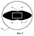
на фиг. 3 - вид сверху на компонент по фиг. 2;
на фиг. 4 - отделение частиц от смеси;
на фиг. 5 - сбор и удаление частиц с компонента для отделения.List of drawings
Next, as examples, some preferred embodiments of the invention will be described. The accompanying drawings show:
in FIG. 1 - collecting component of the device according to the invention;
in FIG. 2 - component for separating particles from the mixture, side view;
in FIG. 3 is a plan view of the component of FIG. 2;
in FIG. 4 - separation of particles from the mixture;
in FIG. 5 - collection and removal of particles from the component for separation.
Сведения, подтверждающие возможность осуществления изобретения
Как показано на фиг. 1, собирающий компонент содержит удлиненный защитный корпус 1, в котором имеется канал 2. Нижние концы корпуса 1 и канала 2 выполнены слегка сужающимися. Чтобы его было удобнее держать, на верхнем конце корпуса 2 имеется фланец 3.Information confirming the possibility of carrying out the invention
As shown in FIG. 1, the collecting component comprises an elongated protective housing 1, in which there is a channel 2. The lower ends of the housing 1 and channel 2 are made slightly tapering. To make it easier to hold, there is a flange 3 at the upper end of the housing 2.
В канале 2 свободно размещается магнитный стержень 4. Он состоит из вертикального стержневого магнита 5 в нижней его части и расположенного над ним ферромагнитного штока 6, выполненного как продолжение стержневого магнита. На конце штока 6 имеется рукоятка 7. Magnetic rod 4 is freely placed in channel 2. It consists of a vertical rod magnet 5 in its lower part and a ferromagnetic rod 6 located above it, made as a continuation of the rod magnet. At the end of the stem 6 there is a handle 7.
Нижний конец защитного корпуса снабжен оконечностью в форме конического острия 8 с вогнутой поверхностью. Длина этого острия примерно соответствует ширине нижнего конца корпуса. The lower end of the protective housing is equipped with a tip in the form of a conical tip 8 with a concave surface. The length of this tip roughly corresponds to the width of the lower end of the body.
Отношение длины магнита 5 к его диаметру составляет примерно 10:1, а отношение длины штока к длине магнита - примерно 5:1. Шток несколько толще, чем магнит, и верхний конец магнита входит внутрь нижнего конца штока на длину, примерно вдвое превышающую диаметр магнита. The ratio of the length of the magnet 5 to its diameter is approximately 10: 1, and the ratio of the length of the rod to the length of the magnet is approximately 5: 1. The rod is slightly thicker than the magnet, and the upper end of the magnet enters the lower end of the rod by a length approximately twice the diameter of the magnet.
На фиг. 2 и 3 представлен один из вариантов компонента 9 для отделения частиц согласно изобретению, который введен в довольно высокий первый сосуд 10. Сосуд 10 содержит магнитные частицы в смеси, представляющей собой суспензию в жидкости. Компонент 9 для отделения частиц содержит цилиндрический корпус 11, высота которого несколько превышает высоту первого сосуда 10. Наружная поверхность корпуса 11 в своей части, входящей внутрь сосуда 10, образует отделяющую поверхность, формирующую полость 12 с прямоугольным поперечным сечением, проходящую от верхнего торца корпуса почти до его нижнего конца. В полости 12, на ее продольной (вертикальной) оси свободно установлен магнитный стержень 13, на нижнем конце которого имеется удлиненный магнит 14. Поле магнита ориентировано в поперечном направлении относительно полости (т.е. перпендикулярно плоскости изображения на фиг. 2). In FIG. 2 and 3 show one embodiment of the
Основной вариант выполнения поперечного сечения корпуса 11 - это сильно сплющенный эллипс, каждая из сторон которого имеет вогнутость в средней части, так что отделяющая поверхность представляет собой эллипсоид, на противоположных сторонах которого образуются две продольные собирающие канавки 15, подходящие к концам магнита. Поперечный размер и профиль канавок согласован с размерами острия, образующего оконечность 8 защитного корпуса собирающего компонента. Корпус 11 имеет заостренный кончик в нижней своей части. The main embodiment of the cross section of the
Когда стержень 13 находится в полости 12, магнитные частицы под воздействием формируемого стрежнем 13 магнитного поля вытягиваются из смеси в сосуде 10 и аккумулируются в продольных канавках 15 отделяющей поверхности, образуя удлиненные вертикальные полоски 16 (фиг. 4). When the
Когда нужно собрать частицы из полосок 16 для переноса их во второй сосуд, компонент для отделения частиц извлекают из сосуда 10. При этом, благодаря концентрированию отделяемых магнитных частиц в форме удлиненных полосок в узких канавках 15 на отделяющей поверхности, количество жидкости и, следовательно, примесей, извлекаемых вместе с частицами, оказывается очень малым. Тем не менее, частицы настолько увлажнены, что их легко собрать с отделяющей поверхности после того, как воздействие на них магнитного поля, формируемого магнитным стержнем 13 компонента 9, снимают путем отведения этого стержня от отделяющей поверхности этого компонента. When it is necessary to collect particles from strips 16 for transferring them to a second vessel, the component for separating particles is removed from the
Собирают частицы из канавок 15 с помощью собирающего компонента 1 (фиг. 5), путем приведения острия 8 этого компонента в контакт с отделяющей поверхностью компонента для отделения в зоне канавок 15. Выполнение нижней оконечности корпуса 1 собирающего компонента в виде острия 8, в зоне которого обеспечиваются максимальная напряженность и максимальный градиент магнитного поля, формируемого собирающим компонентом с помощью магнитного стержня 4, позволяет оптимизировать механический контакт между отделяющей поверхностью и собирающим компонентом и создать оптимальные условия для сбора частиц. Particles are collected from the
Собранные на острие 8 частицы переносят во второй сосуд (не изображен) очень малого объема, например типа ячеек в HLA-плате. The particles collected at tip 8 are transferred to a second vessel (not shown) of a very small volume, for example, the type of cells in an HLA board.
Оконечность корпуса 1 особенно хорошо приспособлена для переноса частиц именно в очень маленькие сосуды. Длина острия в этом случае слегка превышает высоту ячейки. Когда острие 8 вводят в ячейку, поверхность жидкости, вследствие действия поверхностного натяжения, поднимается по поверхности острия. Поскольку при вводе острия в ячейку воздействие второго магнитного поля снимается (за счет отвода ферромагнитного штока 6 с магнитом 5, входящих в состав магнитного стержня 4, от нижнего конца защитного корпуса 1), край движущейся поверхности жидкости смывает частицы с острия в жидкость. Отделение частиц от острия 8 может быть усилено за счет взбалтывающих движений собирающего компонента. Когда же острие после освобождения магнитных частиц извлекается из ячейки, жидкость движется в направлении кончика острия как единая пленка. Благодаря этому жидкость с частицами в ней полностью отделяется от острия. The extremity of the housing 1 is particularly well adapted for transferring particles into very small vessels. The length of the tip in this case slightly exceeds the height of the cell. When the tip 8 is introduced into the cell, the surface of the liquid, due to the action of surface tension, rises along the surface of the tip. Since, when the tip is inserted into the cell, the influence of the second magnetic field is removed (due to the removal of the ferromagnetic rod 6 with magnet 5 included in the magnetic rod 4 from the lower end of the protective housing 1), the edge of the moving surface of the liquid flushes particles from the tip into the liquid. The separation of particles from the tip 8 can be enhanced by the shaking movements of the collecting component. When, after the release of magnetic particles, the tip is removed from the cell, the liquid moves in the direction of the tip of the tip as a single film. Due to this, the liquid with particles in it is completely separated from the tip.
Помимо описанных, возможны и другие варианты осуществления настоящего изобретения. Например, на отклоняющей поверхности вместо двух может быть выполнена одна канавка 15 для концентрирования магнитных частиц. При использовании второго сосуда специальной формы профиль поперечного сечения острия, выполненного на оконечности собирающего компонента, может быть некруглым. Поэтому в контексте настоящего описания выражения "внутренний диаметр второго сосуда" и "диаметр острия" следует трактовать как их минимальные размеры в поперечном направлении. Очевидно также, что частицы, выделенные на поверхность компонента для отделения частиц из смеси, находившейся в сосуде относительно большого объема, могут быть перенесены с помощью собирающего компонента не в один, а в несколько сосудов малого диаметра. In addition to those described, other embodiments of the present invention are possible. For example, on a deflecting surface, instead of two, one
Claims (13)
Applications Claiming Priority (3)
| Application Number | Priority Date | Filing Date | Title |
|---|---|---|---|
| FI944940A FI944940A0 (en) | 1994-10-20 | 1994-10-20 | Tvaofasigt separeringsfoerfarande |
| FI944940 | 1994-10-20 | ||
| PCT/FI1995/000580 WO1996012961A1 (en) | 1994-10-20 | 1995-10-20 | Two-stage separation method |
Publications (2)
| Publication Number | Publication Date |
|---|---|
| RU97106753A RU97106753A (en) | 1999-04-27 |
| RU2142632C1 true RU2142632C1 (en) | 1999-12-10 |
Family
ID=8541637
Family Applications (1)
| Application Number | Title | Priority Date | Filing Date |
|---|---|---|---|
| RU97106753A RU2142632C1 (en) | 1994-10-20 | 1995-10-20 | Two-stage process of separation of particles and gear for its realization |
Country Status (8)
| Country | Link |
|---|---|
| US (1) | US6065605A (en) |
| EP (1) | EP0787297B1 (en) |
| JP (1) | JP3684421B2 (en) |
| DE (1) | DE69525463T2 (en) |
| FI (2) | FI944940A0 (en) |
| NO (1) | NO317665B1 (en) |
| RU (1) | RU2142632C1 (en) |
| WO (1) | WO1996012961A1 (en) |
Families Citing this family (21)
| Publication number | Priority date | Publication date | Assignee | Title |
|---|---|---|---|---|
| EP0681700B1 (en) | 1993-02-01 | 2001-11-21 | Thermo Labsystems Oy | Method for magnetic particle specific binding assay |
| FI930440A0 (en) | 1993-02-01 | 1993-02-01 | Labsystems Oy | BESTAEMNINGSFOERFARANDE |
| FI944939A0 (en) * | 1994-10-20 | 1994-10-20 | Labsystems Oy | Foerfarande Foer separering av partiklar |
| FI944937A0 (en) | 1994-10-20 | 1994-10-20 | Labsystems Oy | Separeringsanordning |
| FI944938A0 (en) * | 1994-10-20 | 1994-10-20 | Labsystems Oy | Foerflyttningsanordning |
| FI944940A0 (en) * | 1994-10-20 | 1994-10-20 | Labsystems Oy | Tvaofasigt separeringsfoerfarande |
| EP0963554B1 (en) * | 1997-01-30 | 2002-10-23 | MERCK PATENT GmbH | Method for the immunological determination of an analyte |
| FI102906B1 (en) * | 1998-02-23 | 1999-03-15 | Bio Nobile Oy | Process and means for transporting a substance |
| KR100445560B1 (en) * | 2001-10-31 | 2004-08-21 | (주)바이오넥스 | Method of manufacturing kit for isolating nucleic acids or biological materials, kit manufactured by the method, and apparatus using the kit |
| US7514270B2 (en) * | 2002-04-12 | 2009-04-07 | Instrumentation Laboratory Company | Immunoassay probe |
| FI20040159A0 (en) | 2003-10-20 | 2004-02-02 | Bio Mobile Oy | Magnetic transfer method, microparticle transfer device, and reaction unit |
| US8211386B2 (en) * | 2004-06-08 | 2012-07-03 | Biokit, S.A. | Tapered cuvette and method of collecting magnetic particles |
| US7473407B2 (en) * | 2004-11-19 | 2009-01-06 | Solvay Chemicals | Magnetic separation process for trona |
| FI20051248L (en) | 2005-12-02 | 2007-06-03 | Bio Nobile Oy | Enrichment unit and enrichment method for biological components |
| CA2685229A1 (en) * | 2007-04-26 | 2008-11-06 | Her Majesty The Queen In Right Of Canada, As Represented By The Minister Of Health | Process for isolating microorganisms from samples and system, apparatus and compositions therefor |
| DE102007045474A1 (en) * | 2007-09-21 | 2009-04-02 | Qiagen Gmbh | Apparatus and method for treating liquids with magnetic particles |
| US8222048B2 (en) | 2007-11-05 | 2012-07-17 | Abbott Laboratories | Automated analyzer for clinical laboratory |
| US8071395B2 (en) * | 2007-12-12 | 2011-12-06 | The Board Of Trustees Of The Leland Stanford Junior University | Methods and apparatus for magnetic separation of cells |
| KR101384142B1 (en) * | 2007-12-28 | 2014-04-14 | 삼성디스플레이 주식회사 | Display substrate, method for manufacturing the display substrate and display apparatus having the display substrate |
| US20100297778A1 (en) * | 2009-05-20 | 2010-11-25 | Abbott Laboratories | Conjugate Having Cleavable Linking Agent |
| CN104923395B (en) * | 2015-04-17 | 2018-02-16 | 安徽达健医学科技有限公司 | For separating and shifting the electromagnetism electromotion integrated apparatus of magnetic-particle |
Family Cites Families (47)
| Publication number | Priority date | Publication date | Assignee | Title |
|---|---|---|---|---|
| US2471764A (en) * | 1946-01-31 | 1949-05-31 | Carl H Miller | Magnetic hand pickup tool |
| US3826619A (en) * | 1971-12-21 | 1974-07-30 | Abbott Lab | Test apparatus for direct radioimmuno-assay for antigens and their antibodies |
| BE791340A (en) * | 1972-01-06 | 1973-03-01 | Becton Dickinson Co | NEW METHOD AND APPARATUS FOR TAKING A CULTURE AND IDENTIFYING MICRO-ORGANISMS OF MOODS |
| US3985649A (en) * | 1974-11-25 | 1976-10-12 | Eddelman Roy T | Ferromagnetic separation process and material |
| US3970518A (en) * | 1975-07-01 | 1976-07-20 | General Electric Company | Magnetic separation of biological particles |
| US4018886A (en) * | 1975-07-01 | 1977-04-19 | General Electric Company | Diagnostic method and device employing protein-coated magnetic particles |
| US4272510A (en) * | 1976-04-26 | 1981-06-09 | Smith Kendall O | Magnetic attraction transfer process for use in solid phase radioimmunoassays and in other assay methods |
| US4200613A (en) * | 1977-06-03 | 1980-04-29 | Ramco Laboratories Inc. | Radioimmunoassay apparatus |
| GB1584129A (en) * | 1977-06-10 | 1981-02-04 | Nayak P | Method and apparatus for performing in vitro clinical diagnostic tests using a solid phase assay system |
| US4115535A (en) * | 1977-06-22 | 1978-09-19 | General Electric Company | Diagnostic method employing a mixture of normally separable protein-coated particles |
| US4378344A (en) * | 1979-09-28 | 1983-03-29 | Ventrex Laboratories, Inc. | Method and apparatus for performing multiple, simultaneous in vitro diagnostic tests using a solid phase system |
| EP0030086B2 (en) * | 1979-11-13 | 1990-03-14 | TECHNICON INSTRUMENTS CORPORATION (a New York corporation) | Test-tube assembly, kit for making it and method of manual immunoassay |
| GB2107053A (en) * | 1980-06-20 | 1983-04-20 | Unilever Plc | Processes and apparatus for carrying out specific binding assays |
| JPS585657A (en) * | 1981-07-01 | 1983-01-13 | Toyo Jozo Co Ltd | Immunity measuring element and measuring method employing said element |
| JPS585656A (en) * | 1981-07-01 | 1983-01-13 | Olympus Optical Co Ltd | Deciding method for particle agglomeration |
| JPS585658A (en) * | 1981-07-02 | 1983-01-13 | Japan Synthetic Rubber Co Ltd | Carrier for immunity serological inspecting reagent |
| GB2147698B (en) * | 1981-11-17 | 1986-05-08 | Unilever Plc | Test apparatus for immunoassay |
| IL73187A0 (en) * | 1983-10-11 | 1985-01-31 | Lilly Co Eli | Purification of esters of alkanoic acids |
| FR2554016B1 (en) * | 1983-10-27 | 1986-08-08 | Pasteur Institut | IMPROVEMENTS IN MAGNETIC MEANS FOR REMOVING MAGNETIC GEL BALLS FROM A DOSING FLUID |
| FI842992A0 (en) * | 1984-07-26 | 1984-07-26 | Labsystems Oy | IMMUNOLOGISKT DEFINITIONSFOERFARANDE. |
| FR2572178B1 (en) * | 1984-10-23 | 1988-10-28 | Pasteur Institut | NOVEL MAGNETIC DEVICE FOR REMOVING MAGNETIC GEL BALLS FROM AN ANALYZED MEDIUM AND TRANSFERRING THESE TO AN IMMUNOENZYMATIC ASSAY MEDIUM |
| US4839276A (en) * | 1984-12-05 | 1989-06-13 | Technicon Instruments Corporation | Interference - resistant liposome specific binding assay |
| FI851702A0 (en) * | 1985-04-29 | 1985-04-29 | Labsystems Oy | FOERFARANDE OCH ANORDNING FOER UTFOERING IMMUNOBESTAEMNINGAR. |
| SE8601143L (en) * | 1986-03-12 | 1987-09-13 | Carbematrix Ab | SET AND DEVICE FOR COLLECTION AND DISTRIBUTION OF FERROMAGNETIC PARTICLES IN A FLUID MEDIUM |
| JPS635263A (en) * | 1986-06-24 | 1988-01-11 | Yasunobu Tsukioka | Examination of blood |
| JPS635266A (en) * | 1986-06-25 | 1988-01-11 | Toshiba Corp | Analyser |
| JPS635265A (en) * | 1986-06-25 | 1988-01-11 | Toshiba Corp | Method for immunoassay |
| US4891321A (en) * | 1987-10-21 | 1990-01-02 | Hubscher Thomas T | Apparatus for performing determinations of immune reactants in biological fluids |
| DE3850635T2 (en) * | 1987-11-16 | 1995-03-02 | Amoco Corp | Magnetic separator and method for use in heterogeneous tests. |
| US4895650A (en) * | 1988-02-25 | 1990-01-23 | Gen-Probe Incorporated | Magnetic separation rack for diagnostic assays |
| EP0351857B1 (en) * | 1988-07-20 | 1994-11-30 | Olympus Optical Co., Ltd. | Immunoassay method using magnetic marker particles |
| US5147529A (en) * | 1988-08-10 | 1992-09-15 | E. I. Du Pont De Nemours And Company | Method for automatically processing magnetic solid phase reagents |
| EP0418026B1 (en) * | 1989-09-13 | 1994-11-30 | Kabushiki Kaisha Tiyoda Seisakusho | Apparatus for pretreating cells for flow cytometry |
| JPH0477225A (en) * | 1990-07-18 | 1992-03-11 | Nissei Plastics Ind Co | Injection molder |
| US5200084A (en) * | 1990-09-26 | 1993-04-06 | Immunicon Corporation | Apparatus and methods for magnetic separation |
| EP0479448A3 (en) * | 1990-10-02 | 1992-12-23 | Beckman Instruments, Inc. | Magnetic separation device |
| US5466574A (en) * | 1991-03-25 | 1995-11-14 | Immunivest Corporation | Apparatus and methods for magnetic separation featuring external magnetic means |
| JPH0792459B2 (en) * | 1991-06-18 | 1995-10-09 | オリンパス光学工業株式会社 | Immunological test method |
| FR2679660B1 (en) * | 1991-07-22 | 1993-11-12 | Pasteur Diagnostics | METHOD AND MAGNETIC DEVICE FOR IMMUNOLOGICAL ANALYSIS ON A SOLID PHASE. |
| FI922687A0 (en) * | 1992-06-10 | 1992-06-10 | Labsystems Oy | AVLAEGSNINGSANORDNING. |
| EP0681700B1 (en) * | 1993-02-01 | 2001-11-21 | Thermo Labsystems Oy | Method for magnetic particle specific binding assay |
| FI930440A0 (en) * | 1993-02-01 | 1993-02-01 | Labsystems Oy | BESTAEMNINGSFOERFARANDE |
| FI932866A0 (en) * | 1993-06-21 | 1993-06-21 | Labsystems Oy | Separeringsfoerfarande |
| FI944938A0 (en) * | 1994-10-20 | 1994-10-20 | Labsystems Oy | Foerflyttningsanordning |
| FI944937A0 (en) * | 1994-10-20 | 1994-10-20 | Labsystems Oy | Separeringsanordning |
| FI944940A0 (en) * | 1994-10-20 | 1994-10-20 | Labsystems Oy | Tvaofasigt separeringsfoerfarande |
| FI944939A0 (en) * | 1994-10-20 | 1994-10-20 | Labsystems Oy | Foerfarande Foer separering av partiklar |
-
1994
- 1994-10-20 FI FI944940A patent/FI944940A0/en not_active Application Discontinuation
-
1995
- 1995-10-20 JP JP51366696A patent/JP3684421B2/en not_active Expired - Lifetime
- 1995-10-20 EP EP95934685A patent/EP0787297B1/en not_active Expired - Lifetime
- 1995-10-20 US US08/817,605 patent/US6065605A/en not_active Expired - Lifetime
- 1995-10-20 DE DE69525463T patent/DE69525463T2/en not_active Expired - Lifetime
- 1995-10-20 RU RU97106753A patent/RU2142632C1/en active
- 1995-10-20 WO PCT/FI1995/000580 patent/WO1996012961A1/en active IP Right Grant
-
1997
- 1997-04-18 FI FI971668A patent/FI119661B/en not_active IP Right Cessation
- 1997-04-18 NO NO19971807A patent/NO317665B1/en not_active IP Right Cessation
Also Published As
| Publication number | Publication date |
|---|---|
| WO1996012961A1 (en) | 1996-05-02 |
| JP3684421B2 (en) | 2005-08-17 |
| NO971807L (en) | 1997-04-18 |
| JPH10508101A (en) | 1998-08-04 |
| NO971807D0 (en) | 1997-04-18 |
| FI944940A0 (en) | 1994-10-20 |
| FI119661B (en) | 2009-01-30 |
| DE69525463T2 (en) | 2002-11-21 |
| US6065605A (en) | 2000-05-23 |
| NO317665B1 (en) | 2004-11-29 |
| FI971668A0 (en) | 1997-04-18 |
| DE69525463D1 (en) | 2002-03-21 |
| FI971668A (en) | 1997-04-18 |
| EP0787297A1 (en) | 1997-08-06 |
| EP0787297B1 (en) | 2002-02-13 |
Similar Documents
| Publication | Publication Date | Title |
|---|---|---|
| RU2142632C1 (en) | Two-stage process of separation of particles and gear for its realization | |
| RU2142633C1 (en) | Process separating magnetic microparticles with their preliminary concentration and device for its implementation | |
| RU2142631C1 (en) | Method and device to transfer magnetic particles | |
| RU2138801C1 (en) | Particle separation device | |
| RU97106752A (en) | MAGNETIC PARTICLE TRANSFER | |
| JP3254681B2 (en) | Separation method and separation device | |
| EP0691541A2 (en) | Method and device for separating magnetic particles | |
| US20080170966A1 (en) | Flux Concentrator for Biomagnetic Particle Transfer Device | |
| EP1040355A1 (en) | Method and apparatus for wash, resuspension, recollection and localization of magnetizable particles in assays using magnetic separation technology | |
| RU97106755A (en) | PARTICLE SEPARATION DEVICE | |
| RU97106754A (en) | SEPARATION OF MAGNETIC MICROPARTICLES WITH PRELIMINARY CONCENTRATION | |
| RU97106753A (en) | TWO-STEP PARTICLE SEPARATION METHOD | |
| KR102338887B1 (en) | Device for insertion into an imaging system | |
| JP2567068B2 (en) | Electron microscope sample preparation method and electron microscope sample preparation instrument | |
| FI120469B (en) | Magnetic particle separation method including a pre-concentration step | |
| FI121322B (en) | Use of a device for separating microparticles | |
| US20190270093A1 (en) | Magnetic tool and method of collecting magnetic particles using same |