RU2139178C1 - Machine tool for assembling fuel elements to fuel assemblies - Google Patents
Machine tool for assembling fuel elements to fuel assemblies Download PDFInfo
- Publication number
- RU2139178C1 RU2139178C1 RU97119255A RU97119255A RU2139178C1 RU 2139178 C1 RU2139178 C1 RU 2139178C1 RU 97119255 A RU97119255 A RU 97119255A RU 97119255 A RU97119255 A RU 97119255A RU 2139178 C1 RU2139178 C1 RU 2139178C1
- Authority
- RU
- Russia
- Prior art keywords
- fuel elements
- fuel
- horizontal
- technological
- pusher
- Prior art date
Links
Images


Landscapes
- Monitoring And Testing Of Nuclear Reactors (AREA)
Abstract
Description
Изобретение относится к механосборочному производству, в частности, к станкам для сборки тепловыделяющих элементов (ТВЭЛ) в тепловыделяющие сборки (ТВС) преимущественно для водо-водяных энергетических реакторов ВВЭР. The invention relates to mechanical assembly production, in particular, to machines for assembling fuel elements (fuel elements) into fuel assemblies (fuel assemblies) mainly for water-cooled VVER power reactors.
В производстве ТВС для атомных энергетических реакторов наиболее ответственным является процесс запрессовки ТВЭЛов, имеющих длину промерно 4 м, в ячейки технологических дистанционирующих решеток, т.к ТВЭЛы имеют практически нулевую осевую жесткость и оболочку из циркония, который отличается склонностью к разъедающей коррозии, появляющейся в результате истирания циркония между соприкасающимися поверхностями даже при отсутствии коррозионной среды под влиянием колебаний при очень маленьких амплитудах, а в некоторых случаях при незначительных нагрузках (см. Металлургия циркония, перевод с английского. Под редакцией Г.А.Меерсона и Ю.В.Гагаринского. Издательство иностранной литературы, М., 1959 г., стр.298). Разъедающая коррозия поверхности оболочки ТВЭЛа не исключает его разгерметицацию в атомном реакторе, что ставит перед процессом сборки ТВЭЛов в ТВС условие по защите поверхности ТВЭЛ перед их сборкой в ТВС покрытием лаками, смазками и применением наконечников. Вторым условием после сборки ТВС является ее транспортировка в горизонтальном положении, т. к известные станки предусматривают горизонтальную сборку ТВЭЛ в ТВС, то необходимым приложением к станку является автооператор транспортировки ТВС в горизонтальном положении со станка сборки ТВС на кантователь перевода ТВС из горизонтального положения в вертикальное для установки головки и хвостовика на собранную ТВС. Поскольку ТВЭЛы имеют практически нулевую осевую жесткость, требуется на автооператоре применять множество захватных лап для исключения прогиба ТВС, но при этом ТВЭЛы ТВС вступают в контакт с захватными лапами, что не исключает их повреждения. In the manufacture of fuel assemblies for nuclear power reactors, the most responsible is the process of pressing fuel rods having a length of about 4 m into the cells of technological spacing grids, because fuel rods have practically zero axial stiffness and a zirconium shell, which is characterized by a tendency to corrosive corrosion resulting from abrasion of zirconium between contacting surfaces even in the absence of a corrosive medium under the influence of vibrations at very small amplitudes, and in some cases with a slight stress-negative (see. zirconium metallurgy, translation from English. Edited G.A.Meersona and Yu.V.Gagarinskogo. Publisher Foreign Literature, Moscow, 1959, str.298). Corrosive corrosion of the surface of a fuel rod cladding does not preclude its depressurization in an atomic reactor, which poses a condition for the assembly of fuel rods in a fuel assembly to protect the surface of a fuel rod before assembling it in a fuel assembly coated with varnishes, greases, and the use of tips. The second condition after assembling a fuel assembly is its transportation in a horizontal position, since well-known machines provide for the horizontal assembly of fuel elements in a fuel assembly, the necessary application to the machine is the auto-operator of transporting fuel assemblies in a horizontal position from a fuel assembly machine to a tilter for transferring fuel assemblies from horizontal to vertical position for installation of the head and shank on the assembled fuel assembly. Since fuel elements have practically zero axial stiffness, it is required to use a lot of gripping paws on the auto operator to exclude deflection of the fuel assemblies, but at the same time fuel assemblies of fuel assemblies come into contact with the gripping legs, which does not exclude their damage.
Третьим условием является радиационная безопасность персонала при работах с высокоактивным материалом, например, с ТВЭЛами с уран-плутониевым топливом, т.е. в этом случае наиболее важным является дистанционное управление станком и автоматическая сборка ТВЭЛ в ТВС. Известен станок для заталкивания трубчатых заготовок, состоящий из механизма заталкивания трубчатых заготовок с приводным толкателем и механизма горизонтального и вертикального шагового перемещения (см. GB, патент N 1385297, B 23 P 15/26, 1972 г). The third condition is the radiation safety of personnel when working with highly active material, for example, fuel elements with uranium-plutonium fuel, i.e. in this case, the most important is the remote control of the machine and the automatic assembly of the fuel elements in the fuel assembly. A known machine for pushing tubular billets, consisting of a mechanism for pushing tubular billets with a drive pusher and a horizontal and vertical step movement mechanism (see GB, patent N 1385297, B 23
Недостатком этого станка является низкая точность позиционирования, т.е. к ошибке срабатывания конечных выключателей добавляется деформация привода основания и кинематической неточности механизма перемещения, что не исключает изгиба ТВЭЛа при его заталкивании (запрессовке) в ячейки технологических дистанционирующих решеток, отклонения ТВЭЛа от оси заталкивания (запрессовки), деформации его и технологической дистанционирующей решетки и перевод последних в брак, что снижает выход годных ТВС и производительность, т. к. потребуются определенные трудозатраты для удаления деформированного ТВЭЛа и замены деформированной технологической дистанционирующей решетки. The disadvantage of this machine is its low positioning accuracy, i.e. to the operation error of the limit switches, deformation of the base drive and kinematic inaccuracy of the movement mechanism is added, which does not exclude the bending of the fuel rod when it is pushed (pressed) into the cells of the technological spacer grids, the deflection of the fuel rod from the axis of pushing (press-fit), its deformation and the technological spacer grid, and translation of the latter marriage, which reduces the yield of fuel assemblies and performance, because it will take some work to remove the deformed fuel rod and replace the defor technological spacing grid.
Наиболее близким по технической сущности и достигаемому эффекту является станок для сборки ТВЭЛ в ТВС, преимущественно для водо-водяного энергетического реактора, содержащий станину, накопитель в виде наклонных реек с отсекателями поштучной подачи ТВЭЛ, механизм осевого перемещения ТВЭЛа в виде рольганга с прижимными роликами, механизм запрессовки ТВЭЛа в технологические дистанционирующие решетки в виде подпружиненного толкателя и цепной передачи с регулируемым усилием запрессовки, механизм оснащения ТВЭЛа съемными наконечниками конической формы, фильеру, установленную соосно механизму запрессовки с емкостью подачи смазки, механизм горизонтального и вертикального перемещения стапеля координатного, обоймы под технологические дистанционирующие решетки, датчики контроля длины ТВЭЛа вместе с наконечником, ложемент для установки транспортной кассеты с ТВЭЛами, размещенными на ее полках и систему управления (см. патент Российской федерации N 2065350 по заявке N 5048760/08 от 18.06.92г. Опубликован 20.08.96г., МКИ B 23 K 37/4, B 23 P 15/26). The closest in technical essence and the achieved effect is a machine for assembling fuel elements in fuel assemblies, mainly for a pressurized water reactor, containing a bed, a drive in the form of inclined rails with cut-off pieces for fuel elements, an axial movement mechanism for a fuel element in the form of a live roll with pressure rollers, a mechanism press-fit the fuel rod into the technological spacer grids in the form of a spring-loaded pusher and chain transmission with an adjustable pressing force, the mechanism of equipping the fuel rod with removable tips to onical form, a die installed coaxially to the press-in mechanism with a lubricant supply capacity, a mechanism for horizontal and vertical movement of the coordinate building berth, clips for technological spacing grids, fuel rod length monitoring sensors together with a tip, a lodgement for installing a transport cassette with fuel rods placed on its shelves and a system management (see the patent of the Russian Federation N 2065350 on the application N 5048760/08 from 06/18/92. Published on 08/20/96, MKI B 23 K 37/4, B 23
Станок предусматривает использование ТВЭЛов, которые были предварительно покрыты лаком, высушены на установке лакового покрытия и скомплектованы в транспортную межоперационную кассету. The machine provides for the use of fuel rods, which were previously coated with varnish, dried at the installation of varnish coating and equipped in a transport inter-operation cassette.
Не исключалось повреждения поверхности ТВЭЛов в механизме осевого перемещения - рольганге с прижимными роликами в процессе запрессовки ТВЭЛов в ячейки технологических дистанционирующих решеток за счет истирания поверхности ТВЭЛов поверхностью вращающихся роликов. Damage to the surface of the fuel rods in the axial movement mechanism was not excluded - a roller table with pressure rollers during the pressing of the fuel rods into the cells of the technological spacer grids due to the abrasion of the surface of the fuel rods by the surface of the rotating rollers.
По мере сборки ТВС на стапеле координатном, имеющем механизмы вертикального и горизонтального шагового перемещения, вес стапеля координатного увеличивался на величину веса ТВС примерно на 700 кг к собственному весу, что вело к возрастанию нагрузок на механизмы вертикального и горизонтального перемещения стапеля координатного, требовало увеличения мощности приводов механизмов вертикального и горизонтального перемещения стапеля координатного. При этом возрастали инерционность механизмов вертикального и горизонтального перемещения стапеля координатного, снижалась точность позицирования, что не исключало смещения оси ячеек технологических дистанционирующих решеток относительно оси запрессовки ТВЭЛа и выводу в брак как ТВЭЛа, так и технологической дистанционирующей решетки. Непосредственно в станке не был предусмотрен кантователь ТВС из горизонтального положения в вертикальное положение, в связи с чем необходимым приложением к станку является автооператор горизонтальной транспортировки ТВС на станок-кантователь для установки головки и хвостовика на ТВС и их закрепления к ТВС. В силу нулевой осевой жесткости ТВЭЛ автооператор имеет множество грузозахватных лап горизонтальной транспортировки ТВС на станок-кантователь для исключения самопроизвольной деформации ТВС. В процессе горизонтальной транспортировки ТВС не исключалось повреждение ТВЭлов грузозахватными лапами. As fuel assemblies were assembled on a coordinate slipway with vertical and horizontal stepwise movement mechanisms, the weight of the coordinate slipway increased by the weight of the fuel assembly by about 700 kg to its own weight, which led to an increase in loads on the mechanisms of vertical and horizontal movement of the coordinate slipway, requiring an increase in drive power mechanisms of vertical and horizontal movement of the slipway coordinate. At the same time, the inertia of the mechanisms of vertical and horizontal movement of the slipway increased, the accuracy of positioning decreased, which did not exclude the displacement of the cell axis of the technological spacer grids relative to the insertion axis of the fuel rod and the marriage of both the fuel rod and the technological spacer grid. Directly in the machine, the fuel assembly tilter was not provided from a horizontal position to a vertical position, in connection with which the necessary application to the machine is the operator of horizontal transportation of fuel assemblies to the tipper machine for installing the head and shank on the fuel assemblies and securing them to the fuel assemblies. Due to the zero axial stiffness of the fuel element, the auto operator has many load-gripping legs for horizontal transportation of fuel assemblies to the tilting machine to exclude spontaneous deformation of the fuel assemblies. In the process of horizontal transportation of fuel assemblies, damage to the fuel elements by gripping legs was not ruled out.
Технической задачей изобретения является повышение выхода годных ТВС, повышение производительности, расширение технологических возможностей и улучшение условий радиационной безопасности. An object of the invention is to increase the yield of fuel assemblies, increase productivity, expand technological capabilities and improve radiation safety conditions.
Это решение технической задачи достигается тем, что в станке для сборки тепловыделяющих элементов в тепловыделяющие сборки, преимущественно для водо-водяного энергетического реактора, содержащем станину с верхней рабочей поверхностью, накопитель тепловыделяющих элементов, выполненный в виде скатов с отсекателями поштучной подачи тепловыделяющих элементов на позицию запрессовки, механизм осевого перемещения тепловыделяющих элементов в виде рольганга с прижимными роликами, механизм запрессовки тепловыделяющих элементов в технологические дистанционирующие решетки в виде подпружиненного толкателя и цепной передачи с регулируемым усилием запрессовки, механизм оснащения тепловыделяющих элементов съемными наконечниками конической формы, фильеру, установленную соосно механизму запрессовки и оснащенную емкостью подачи смазки, стапель координатный, установленный с возможностью горизонтального и вертикального перемещения, механизмы горизонтального и вертикального перемещения стапеля, обоймы под технологические дистанционирующие решетки, датчики контроля длины тепловыделяющих элементов с наконечником, транспортную межоперационную кассету с полками для размещения тепловыделяющих элементов, ложемент для установки транспортной межоперационной кассеты и систему управления. This solution to the technical problem is achieved by the fact that in the machine for assembling fuel elements into fuel assemblies, mainly for a pressurized water reactor containing a bed with an upper working surface, the storage of fuel elements made in the form of slopes with shutters for supplying fuel elements to the insertion position , the mechanism of axial movement of the fuel elements in the form of a roller table with pressure rollers, the mechanism for mounting the fuel elements into the technologist distance spacers in the form of a spring-loaded pusher and a chain transmission with an adjustable pressing force, a mechanism for equipping the heat-generating elements with removable conical shaped tips, a die installed coaxially to the pressing mechanism and equipped with a lubricant supply tank, a coordinate slip, installed with the possibility of horizontal and vertical movement, horizontal and vertical movement of the slipway, clips for technological spacing grids, length control sensors fuel elements with a tip, a transport inter-operation cassette with shelves for accommodating fuel elements, a lodgement for installing a transport inter-operational cassette and a control system.
Другими отличиями является то, что обоймы смонтированы с возможностью вращения вокруг своей оси и снабжены приводом вращения, полый толкатель с цанговым зажимом на конце и двумя механизмами раскрытия цангового зажима, первый из которых выполнен в виде выдвижной вилки с приводом возвратно- поступательного движения и размещен на балке поперечно полому толкателю, а второй - в виде силового цилиндра, взаимодействующего с шарнирно-поворотным рычагом и с пружиной зажима, при этом подпружиненный толкатель выполнен съемным для обеспечения замены его на полый толкатель; накопитель в виде скатов выполнен шарнирно-поворотным с изменением угла наклона;
использование в качестве полимерного материала для роликов капролона.Other differences are that the clips are mounted for rotation around its axis and equipped with a rotation drive, a hollow pusher with a collet clamp at the end and two collet opening mechanisms, the first of which is made in the form of a retractable fork with a reciprocating drive and placed on beam transversely to the hollow pusher, and the second in the form of a power cylinder interacting with a pivot-swing arm and a clamp spring, while the spring-loaded pusher is removable to provide replacement us his hollow pusher; the drive in the form of slopes is made swivel with a change in the angle of inclination;
use as a polymer material for caprolon rollers.
Такое выполнение стапеля координатного позволит стабилизировать его вес, устранить перепады веса в сторону увеличения на примерно 700 кг, в момент сборки ТВС, устранить инерционность его перемещения в вертикальном и горизонтальном направлении и повысить выход годных ТВС. This embodiment of the coordinate slipway will stabilize its weight, eliminate weight differences in the direction of increase by about 700 kg, at the time of assembly of the fuel assemblies, eliminate the inertia of its movement in the vertical and horizontal direction and increase the yield of suitable fuel assemblies.
Выполнение станины шарнирно-поворотной из горизонтального положения в вертикальное, и наоборот, с боковыми и нижними ограничителями с возможностью поворота обойм вокруг своей оси позволит исключить транспортирование ТВС в горизонтальном положении, исключить автооператор горизонтальной транспортировки, а следовательно, и контакт ТВЭЛов с захватными лапами автооператора, что повысит выход годных за счет исключения повреждений поверхности ТВЭЛов и осуществить непосредственно на станке установку головки и хвостовика на ТВС без ее транспортировки со станка на станок, что имело место в патенте N 2065350, а установка ограничителей позволит осуществлять жесткую фиксацию станины в горизонтальном положении, что особенно важно при координатном перемещении стапеля и балки при запрессовке ТВЭЛов в ячейки дистанционирующих решеток, установленных в обоймах на станине, и повысит выход годных, расширит технологические возможности, повысит производительность. The implementation of the hinged-swivel bed from horizontal to vertical, and vice versa, with side and lower stops with the ability to rotate the clips around its axis will eliminate the transportation of fuel assemblies in a horizontal position, exclude the auto-operator of horizontal transportation, and therefore the contact of the fuel rods with the gripping legs of the auto-operator, which will increase the yield by eliminating surface damage of fuel rods and install the head and shank on the fuel assembly directly on the machine without its trans sorting from machine to machine, which was the case in patent N 2065350, and the installation of stops will allow rigid fixation of the bed in a horizontal position, which is especially important for the coordinate movement of the stock and beam when pressing the fuel rods into the cells of the spacer grids installed in the clips on the bed, and increase yield, expand technological capabilities, increase productivity.
Выполнение прижимных роликов из полимерного материала капролона позволит исключить повреждение поверхности ТВЭЛа, повысить выход годных ТВС. The implementation of the pressure rollers of the polymer material of caprolon will eliminate the damage to the surface of the fuel rod, increase the yield of the fuel assembly.
Выполнение подпружиненного толкателя съемным, заменяемым на полый толкатель с цанговым зажимом на конце и механизмом раскрытия цанги в виде выдвижной вилки с приводом возвратно-поступательного движения и второго механизма раскрытия цангового зажима с силовым цилиндром позволит расширить технологические возможности станка, обеспечить разборку ТВЭЛов из ТВС их вытягиванием из ТВС цанговым зажимом при обратном ходе толкателя или разгрузить транспортный контейнер с ТВЭЛами на накопитель в виде шарнирно поворотных скатов после изменения угла их наклона в сторону транспортной кассеты. The implementation of the spring-loaded pusher is removable, replaceable with a hollow pusher with a collet clamp at the end and a collet opening mechanism in the form of a retractable fork with a reciprocating drive and a second collet clamp opening mechanism with a power cylinder that will expand the technological capabilities of the machine and ensure the removal of fuel rods from the fuel assemblies by pulling them from the fuel assembly with a collet clamp during the reverse stroke of the pusher or unload the transport container with the fuel rods to the drive in the form of articulated rotary slopes after being changed I have an angle of inclination in the direction of transport of the cassette.
Выполнение всех операций на станке в автоматическом режиме и заданной программе позволит использовать ТВЭЛы с уранплутониевым топливом и обеспечить радиационную безопасность персонала. Performing all operations on the machine in the automatic mode and the specified program will allow the use of fuel elements with uranium-plutonium fuel and ensure radiation safety of personnel.
На чертежах представлен станок для сборки тепловыделяющих элементов в тепловыделяющие сборки, где на:
фиг. 1 - станок для сборки ТВЭЛов в ТВС (общий вид станка);
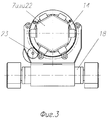
фиг. 2 - станок для сборки ТВЭЛов в ТВС (вид сверху);
фиг. 3 - станина (вид с торца);
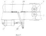
фиг. 4 - второй механизм раскрытия цангового зажима;
фиг. 5 - подпружиненный толкатель с цанговым зажимом (момент захвата ТВЭЛа с раскрытой цангой при разборке ТВС или транспортного контейнера);
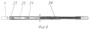
фиг. 6 - подпружиненный толкатель с цанговым зажимом с закрытой цангой;
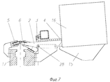
фиг. 7 - накопитель в виде скатов.The drawings show a machine for assembling fuel elements into fuel assemblies, where:
FIG. 1 - a machine for assembling fuel elements in fuel assemblies (general view of the machine);
FIG. 2 - a machine for assembling fuel elements in fuel assemblies (top view);
FIG. 3 - bed (end view);
FIG. 4 - the second mechanism for opening the collet clamp;
FIG. 5 - a spring-loaded pusher with a collet clamp (the moment of gripping the fuel rod with the collet open when disassembling the fuel assembly or transport container);
FIG. 6 - a spring-loaded pusher with a collet clamp with a closed collet;
FIG. 7 - drive in the form of slopes.
Станок для сборки ТВЭЛов в ТВС содержит станину 1, накопитель 2 с отсекателем 3 поштучной подачи ТВЭЛ 4, механизм осевого перемещения ТВЭЛа 4 в виде рольганга 5 с прижимными роликами 6, механизм запрессовки ТВЭЛа 4 в технологические дистанционирующие решетки 7 в виде подпружиненното толкателя 8 и цепной передачи (не показана) с регулируемым усилием запрессовки, механизм 9 оснащения ТВЭЛа 4 съемными наконечниками (не показаны), фильеру 10, установленную соосно механизму запрессовки - подпружиненному толкателю 8 с емкостью подачи смазки (не показаны), механизм 11 горизонтального перемещения, механизм 12 вертикального перемещения стапеля 13 координатного, обоймы 14 под технологические дистанционирующие решетки 7, ложемент 15 для установки транспортной межоперационной кассеты 16 с ТВЭЛами 4, размещенными на ее полках, датчики контроля длины ТВЭЛа вместе с наконечником (не показаны), систему управления (не показана). A machine for assembling fuel elements in a fuel assembly contains a frame 1, a
Подвижный в вертикальном направлении стапель координатный 13 снабжен подвижной в горизонтальном направлении балкой 17, на которой размещены накопитель 2 в виде скатов поштучной подачи ТВЭЛов 4 на позиции запрессовки, механизм осевого перемещения ТВЭЛа 4 в виде рольганга 5 с прижимными роликами 6 из полимерного материала, механизм запрессовки ТВЭЛа 4 в технологические дистанционирующие решетки 7 в виде подпружиненного толкателя 8 и цепной передачи с регулируемым усилием запрессовки, механизм 9 оснащения ТВЭЛа 4 съемными наконечниками конической формы, фильера 10, установленная соосно механизму запрессовки с емкостью подачи смазки, и датчики контроля длины ТВЭЛа 4 вместе с наконечником. The movable in the vertical direction slipway 13 is equipped with a horizontally
Станина 1 выполнена шарнирно-поворотной на шарнире 18 из горизонтального положения в вертикальное, и наоборот, снабжена силовым цилиндром 19, боковыми ограничителями 20 и нижними ограничителями 21 фиксации станины 1 в горизонтальном положении и на ее верхней рабочей поверхности закреплены обоймы 14 для размещения в них дистанционирующих решеток 7 ТВС или контейнера 22 с ТВЭЛами. The frame 1 is pivotally swiveled on the
Обоймы 14 снабжены приводом 23 вращения вокруг своей оси. Подпружиненный толкатель 8 выполнен съемным, заменяемым на полый толкатель 24 с цанговым зажимом 25 на конце с бойком 26, внутри поперечно которому на балке 17 размещен механизм 27 раскрытия цангового зажима 25 в виде выдвижной вилки с приводом возвратно-поступательного движения (не показаны). The
Накопитель 2 в виде скатов снабжен шарниром 28 изменения угла наклона скатов. The
В качестве полимерного материала для роликов использован капролон. As a polymer material for the rollers used caprolon.
На станине 1 предусмотрено гнездо 29 для установки хвостовика 30 к ТВС и гнездо 31 для установки головки (не показана). On the frame 1, a
Второй механизм раскрытия цангового зажима 25 выполнен в виде силового цилиндра 32, взаимодействующего с шарнирно - поворотным рычагом 33 и пружиной 34 цангового зажима 25. The second opening mechanism of the
Станок для сборки ТВЭЛов ТВС работает следующим образом. A machine for assembling fuel assemblies of fuel assemblies works as follows.
На ложемент 15 устанавливают транспортную межоперационную кассету 16 с ТВЭЛами 4 на ее полках. С помощью механизма 11 горизонтального перемещения балка 17 перемещается к транспортной межоперационной кассете 16 и на накопителе 2 в виде скатов открывает полку, межоперационной кассеты 16 и ряд ТВЭЛов 4 с полки скатываются до отсекателей 3, которые поштучно выдают ТВЭЛы 4 на позицию запрессовки, где ТВЭЛ 4 поступает на рольганг 5, прижимается прижимными роликами 6 из полимерного материала и подпружиненным толкателем 8 подается через механизм 9 оснащения ТВЭЛа коническим наконечником, фильеру 10 нанесения смазки, через датчики замера длины ТВЭЛа вместе с наконечником и запрессовывается в ячейки дистанционирующих решеток 7, установленных в обоймах 14. Запрессовка ТВЭЛов проводится до полного заполнения всех ячеек дистанционирующих решеток 7, т.е. по мере запрессовки ТВЭЛа 4 меняется координата запрессовки с помощью механизма 11 горизонтального и механизма 12 вертикального перемещений балки 17 стапеля 13. On the
В гнездо 29 станины 1 устанавливается хвостовик 30, балка 17 смещается в крайнее к межоперационной кассете положение, в гнездо 31 устанавливается головка ТВС. При необходимости собранная ТВС вместе с обоймами 14 может поворачиваться приводом 23 вокруг своей оси. С помощью силового цилиндра 19 на шарнире 18 станина 1 вместе с собранной ТВС поворачивается в вертикальное положение и транспортируется в вертикальном положении на отмывку от лакового покрытия, а станина 1 возвращается в исходное горизонтальное положение и фиксируется боковыми ограничителями 20 и нижними ограничителями 21. In the
Разборка ТВС осуществляется следующим образом. Dismantling fuel assemblies is as follows.
Подпружиненный толкатель 8 заменяется полым подпружиненным толкателем 24 с цанговым зажимом 25, бойком 26 и пружиной 34 внутри. С закрепленной в обоймах 14 ТВС снимается головка. Подпружиненный полый толкатель при подходе к ТВЭЛу, подлежащему удалению, штифтом наезжает на механизм 27 в виде выдвижной вилки и разжимает цанговый зажим 25, толкатель бойком 26 упирается в ТВЭЛ 4, вилка механизма 27 возвращается в исходное положение, цанговый зажим под действием пружины 34 закрывается и обратным ходом толкателя 24 ТВЭЛ 4 извлекается из ТВС. Силовой цилиндр 32 воздействует на шарнирно-поворотный рычаг 33, который в свою очередь воздействует на пружину 34, сжимает ее, раскрывается цанговый зажим 25 и извлеченный из ТВС ТВЭЛ по скатам 2 накопителя, которые повернуты на шарнире 28 с углом наклона в сторону транспортной кассеты скатываются на полки транспортной кассеты 16. Аналогично разбирается транспортный контейнер 22 с ТВЭЛами, который устанавливается в обоймы 14 и полым подпружиненным толкателем с цанговым зажимом ТВЭЛы из контейнера извлекаются. Все операции сборки, разборки на станке проводятся в автоматическом режиме, обеспечивая персоналу радиационную безопасность. The spring-loaded
Claims (5)
решетки, механизм оснащения тепловыделяющих элементов съемными наконечниками, фильера с емкостью подачи смазки и датчики контроля длины тепловыделяющих элементов размещены на упомянутой балке, прижимные ролики выполнены из полимерного материала, станина выполнена шарнирно-поворотной для обеспечения ее перемещения из горизонтального положения в вертикальное и наоборот и снабжена силовым цилиндром и боковыми и нижними ограничителями фиксации ее в горизонтальном положении, а обоймы выполнены с возможностью размещения в них транспортного контейнера с тепловыделяющими элементами и смонтированы на верхней рабочей поверхности станины.1. A machine for assembling fuel elements into fuel assemblies, comprising a bed with a top working surface, a drive of fuel elements made in the form of slopes with cut-off devices for the piece supply of fuel elements to the insertion position, the axial movement of the fuel elements in the form of a roller table with pressure rollers, the pressing mechanism fuel elements into technological spacer grids in the form of a spring-loaded pusher and a chain transmission with adjustable clamping force essinges, a mechanism for equipping fuel elements with conical shaped removable tips, a die installed coaxially with a pressing mechanism and equipped with a lubricant supply tank, a coordinate slipway installed with the possibility of horizontal and vertical movements, mechanisms for horizontal and vertical movement of the slipway, clips for technological spacer grids, control sensors lengths of fuel elements with a tip, transport inter-operation cassette with shelves for heat of fuel elements, a lodgement for installing a transport inter-operational cartridge and a control system, characterized in that it is equipped with a beam placed on a slipway with the ability to move in the horizontal direction, a drive, an axial movement mechanism of the fuel elements, a mechanism for pressing them into technological distance
lattices, a mechanism for equipping the fuel elements with removable tips, a die with a lubricant supply tank and sensors for controlling the length of the fuel elements are placed on the beam, pressure rollers are made of polymer material, the bed is articulated and rotary to ensure its movement from horizontal to vertical and vice versa and is equipped with the power cylinder and the lateral and lower limiters of fixing it in a horizontal position, and the clips are arranged to accommodate transport container with fuel elements and mounted on the upper working surface of the bed.
Priority Applications (1)
| Application Number | Priority Date | Filing Date | Title |
|---|---|---|---|
| RU97119255A RU2139178C1 (en) | 1997-11-18 | 1997-11-18 | Machine tool for assembling fuel elements to fuel assemblies |
Applications Claiming Priority (1)
| Application Number | Priority Date | Filing Date | Title |
|---|---|---|---|
| RU97119255A RU2139178C1 (en) | 1997-11-18 | 1997-11-18 | Machine tool for assembling fuel elements to fuel assemblies |
Publications (2)
| Publication Number | Publication Date |
|---|---|
| RU97119255A RU97119255A (en) | 1999-08-20 |
| RU2139178C1 true RU2139178C1 (en) | 1999-10-10 |
Family
ID=20199179
Family Applications (1)
| Application Number | Title | Priority Date | Filing Date |
|---|---|---|---|
| RU97119255A RU2139178C1 (en) | 1997-11-18 | 1997-11-18 | Machine tool for assembling fuel elements to fuel assemblies |
Country Status (1)
| Country | Link |
|---|---|
| RU (1) | RU2139178C1 (en) |
Cited By (1)
| Publication number | Priority date | Publication date | Assignee | Title |
|---|---|---|---|---|
| CN113020972A (en) * | 2021-03-26 | 2021-06-25 | 重庆双禾科技有限公司 | Automatic assembling process and device for notebook hinge |
-
1997
- 1997-11-18 RU RU97119255A patent/RU2139178C1/en not_active IP Right Cessation
Cited By (1)
| Publication number | Priority date | Publication date | Assignee | Title |
|---|---|---|---|---|
| CN113020972A (en) * | 2021-03-26 | 2021-06-25 | 重庆双禾科技有限公司 | Automatic assembling process and device for notebook hinge |
Similar Documents
| Publication | Publication Date | Title |
|---|---|---|
| EP0455164B1 (en) | A turret punch press with a die exchanging device | |
| US5857377A (en) | System for producing bent sheet-metal articles and components of the system | |
| CN113579416B (en) | Through type straight seam welding machine | |
| DE3237083A1 (en) | LACE BUCK | |
| RU2139178C1 (en) | Machine tool for assembling fuel elements to fuel assemblies | |
| CN110063648A (en) | Automatic cooking device for cup apparatus | |
| JPH0650350B2 (en) | Automatic assembly equipment | |
| DE2330485A1 (en) | DEVICE FOR CHANGING THE TOOLS IN FORGING PRESSES | |
| CN210995354U (en) | Detection device for automobile brake caliper support | |
| CN210731621U (en) | Automatic flaring welding all-in-one of air spring | |
| US4660270A (en) | Apparatus and method for applying an end plug to a fuel rod tube end | |
| CN211028844U (en) | Magnetic sheet insertion apparatus | |
| CN110886790B (en) | Automatic feeding device for automobile hub bearing retainer | |
| CN211516439U (en) | Positioning and rotating device for laser cutting of heavy thick-wall steel pipe | |
| CN214349185U (en) | Transfer and storage device for elbow processing | |
| CN209050008U (en) | A kind of support base assembling equipment | |
| CN116984807B (en) | High-precision automatic welding mechanism | |
| RU2065350C1 (en) | Machine for assembly of fuel elements into fuel blocks | |
| CN217512787U (en) | Blank transferring mechanism in bolt thread rolling process | |
| CN217224295U (en) | Weldment grabbing manipulator | |
| CN110757046A (en) | Automatic welding machine | |
| SU1479251A1 (en) | Pre-welding assembly apparatus | |
| CN114346672B (en) | Automatic assembling device and method for seat tray connecting rod | |
| CN114211245B (en) | Automatic assembly device of seat tray locking mechanism | |
| CN217142935U (en) | Automatic assembly device of seat tray and clamping and conveying mechanism of torsion spring assembly of automatic assembly device |
Legal Events
| Date | Code | Title | Description |
|---|---|---|---|
| MM4A | The patent is invalid due to non-payment of fees |
Effective date: 20081119 |