RU2139103C1 - One-time syringe - Google Patents
One-time syringe Download PDFInfo
- Publication number
- RU2139103C1 RU2139103C1 RU98108556A RU98108556A RU2139103C1 RU 2139103 C1 RU2139103 C1 RU 2139103C1 RU 98108556 A RU98108556 A RU 98108556A RU 98108556 A RU98108556 A RU 98108556A RU 2139103 C1 RU2139103 C1 RU 2139103C1
- Authority
- RU
- Russia
- Prior art keywords
- pin
- nipple
- syringe
- needle
- cavity
- Prior art date
Links
- 210000002445 nipple Anatomy 0.000 claims abstract description 41
- 239000003292 glue Substances 0.000 claims abstract description 6
- 239000007788 liquid Substances 0.000 claims description 14
- 239000012530 fluid Substances 0.000 claims description 10
- 238000004519 manufacturing process Methods 0.000 claims description 7
- 238000005516 engineering process Methods 0.000 claims description 6
- 238000005452 bending Methods 0.000 claims description 4
- 239000002184 metal Substances 0.000 claims description 2
- 230000015572 biosynthetic process Effects 0.000 claims 1
- 230000001066 destructive effect Effects 0.000 claims 1
- 230000003993 interaction Effects 0.000 claims 1
- 238000002347 injection Methods 0.000 abstract description 7
- 239000007924 injection Substances 0.000 abstract description 7
- 238000007789 sealing Methods 0.000 abstract description 6
- 239000003814 drug Substances 0.000 abstract description 2
- 238000009434 installation Methods 0.000 abstract 1
- 239000000126 substance Substances 0.000 abstract 1
- SCYULBFZEHDVBN-UHFFFAOYSA-N 1,1-Dichloroethane Chemical compound CC(Cl)Cl SCYULBFZEHDVBN-UHFFFAOYSA-N 0.000 description 2
- 230000000903 blocking effect Effects 0.000 description 2
- NOESYZHRGYRDHS-UHFFFAOYSA-N insulin Chemical compound N1C(=O)C(NC(=O)C(CCC(N)=O)NC(=O)C(CCC(O)=O)NC(=O)C(C(C)C)NC(=O)C(NC(=O)CN)C(C)CC)CSSCC(C(NC(CO)C(=O)NC(CC(C)C)C(=O)NC(CC=2C=CC(O)=CC=2)C(=O)NC(CCC(N)=O)C(=O)NC(CC(C)C)C(=O)NC(CCC(O)=O)C(=O)NC(CC(N)=O)C(=O)NC(CC=2C=CC(O)=CC=2)C(=O)NC(CSSCC(NC(=O)C(C(C)C)NC(=O)C(CC(C)C)NC(=O)C(CC=2C=CC(O)=CC=2)NC(=O)C(CC(C)C)NC(=O)C(C)NC(=O)C(CCC(O)=O)NC(=O)C(C(C)C)NC(=O)C(CC(C)C)NC(=O)C(CC=2NC=NC=2)NC(=O)C(CO)NC(=O)CNC2=O)C(=O)NCC(=O)NC(CCC(O)=O)C(=O)NC(CCCNC(N)=N)C(=O)NCC(=O)NC(CC=3C=CC=CC=3)C(=O)NC(CC=3C=CC=CC=3)C(=O)NC(CC=3C=CC(O)=CC=3)C(=O)NC(C(C)O)C(=O)N3C(CCC3)C(=O)NC(CCCCN)C(=O)NC(C)C(O)=O)C(=O)NC(CC(N)=O)C(O)=O)=O)NC(=O)C(C(C)CC)NC(=O)C(CO)NC(=O)C(C(C)O)NC(=O)C1CSSCC2NC(=O)C(CC(C)C)NC(=O)C(NC(=O)C(CCC(N)=O)NC(=O)C(CC(N)=O)NC(=O)C(NC(=O)C(N)CC=1C=CC=CC=1)C(C)C)CC1=CN=CN1 NOESYZHRGYRDHS-UHFFFAOYSA-N 0.000 description 2
- 239000004033 plastic Substances 0.000 description 2
- 241001391944 Commicarpus scandens Species 0.000 description 1
- 241000196324 Embryophyta Species 0.000 description 1
- 102000004877 Insulin Human genes 0.000 description 1
- 108090001061 Insulin Proteins 0.000 description 1
- 229910000831 Steel Inorganic materials 0.000 description 1
- 238000009825 accumulation Methods 0.000 description 1
- 238000004026 adhesive bonding Methods 0.000 description 1
- 238000010276 construction Methods 0.000 description 1
- 238000005520 cutting process Methods 0.000 description 1
- 230000006378 damage Effects 0.000 description 1
- 230000007812 deficiency Effects 0.000 description 1
- 238000009792 diffusion process Methods 0.000 description 1
- 238000007688 edging Methods 0.000 description 1
- 238000002474 experimental method Methods 0.000 description 1
- 238000000605 extraction Methods 0.000 description 1
- 229940125396 insulin Drugs 0.000 description 1
- 238000012986 modification Methods 0.000 description 1
- 230000004048 modification Effects 0.000 description 1
- 238000004321 preservation Methods 0.000 description 1
- 238000003825 pressing Methods 0.000 description 1
- 230000001681 protective effect Effects 0.000 description 1
- 239000002904 solvent Substances 0.000 description 1
- 239000010959 steel Substances 0.000 description 1
- 238000003466 welding Methods 0.000 description 1
Images
Landscapes
- Infusion, Injection, And Reservoir Apparatuses (AREA)
Abstract
Description
Изобретение относится к медицине и представляет собой одноразовый шприц для инъекций с автоматической блокировкой повторного использования. The invention relates to medicine and is a disposable injection syringe with automatic reuse lock.
Общеизвестен одноразовый шприц, содержащий цилиндр с коническим выступом, поршень со штоком и иглу. Он производится во многих странах мира, технология его изготовления отлаживалась долго и трудно и уже многие годы неизменна. Польза его для человечества огромна, ее невозможно переоценить. Недостатком шприца является возможность его многократного использования по ошибке или намеренно, поэтому всегда существовала потребность в шприце с автоматической блокировкой повторного использования. Но несмотря на то, что в мире сейчас существует около 1000 патентов на одноразовые шприцы, достойной замены общеизвестному шприцу пока нет. It is well known that a disposable syringe containing a cylinder with a conical protrusion, a piston with a rod and a needle. It is produced in many countries of the world, its manufacturing technology has been debugged for a long time and is difficult and has been unchanged for many years. Its benefits to mankind are enormous; it cannot be overestimated. The disadvantage of the syringe is the possibility of reusing it by mistake or intentionally, so there has always been a need for a syringe with automatic reuse lock. But despite the fact that in the world there are now about 1000 patents for disposable syringes, there is no worthy replacement for a well-known syringe.
Для объяснения такого положения, выявления возможных недостатков, препятствующих внедрению известных конструкций и определения основных критериев, которые должны быть положены в основу разработки альтернативного шприца, проведен анализ недостатков конструкций по следующим странам:
СССР с пат. 1644968 от 27.04.89 по 18378996 от 22.05.91;
Россия с пат. 1761154 от 14.12.89 по 2080881 от 10.06.97;
Англия с пат. 2234175 от 21.03.89 по 2301035 от 26.05.95;
США с пат. 3,291,128 от 12.13.66 по 5,242,405 от 09.93;
Франция с пат. 2652006 от 15.09.89 по 2750052 от 21.06.96;
ФРГ с пат. 3808688 от 31.08.89 по 19528091 от 06.02.97;
ГДР с пат. 300408 от 03.08.89 по 297917 от 01.06.90.To explain this situation, identify possible shortcomings that impede the introduction of known designs and determine the main criteria that should be the basis for the development of an alternative syringe, an analysis of design flaws in the following countries was carried out:
USSR with pat. 1644968 from 04/27/89 to 18378996 from 05/22/91;
Russia with US Pat. 1761154 from 12.14.89 to 2080881 from 10.06.97;
England with US Pat. 2234175 from 03/21/89 to 2301035 from 05/26/95;
U.S. Pat. 3,291,128 from 12.13.66 by 5,242,405 from 09.93;
France with US Pat. 2652006 from 09/15/89 to 2750052 from 06/21/96;
Germany with US Pat. 3808688 from 08/31/89 to 19528091 from 02/06/97;
GDR with US Pat. 300408 from 08/03/89 to 297917 from 06/01/90.
Недостатком первой группы конструкций шприцов, составляющих около 70% от числа исследуемых, является то, что при их разработке не учитывался масштабный фактор. Это значит, что предлагаемая конструкция выполнима только на шприце большого объема и не может быть механически перенесена на шприц малого объема и тем более на инсулиновый - в них она просто не помещается, а если и помещается, то обеспечить прочность подобным, но уже уменьшенным деталям, невозможно. Это приводит к тому, что, принимая ко внедрению такую конструкцию, пришлось бы на шприцах разного объема выполнять конструкции принципиально разные, что усложняет и удорожает производство. Примером могут служить устройства по патентам: Франция 2718358 от 11.07.94; Россия 2062118 от 20.06.96, 2025138 от 22.01.91, 2019195 от 01.01.91 и т.д. The disadvantage of the first group of syringe designs, which make up about 70% of the number of tested, is that during their development the scale factor was not taken into account. This means that the proposed design is feasible only on a large-volume syringe and cannot be mechanically transferred to a small-volume syringe and especially to an insulin syringe - it simply does not fit into them, and if it does, then provide strength to similar but already reduced parts, impossible. This leads to the fact that, taking such a design for implementation, it would be necessary to carry out fundamentally different designs on syringes of different volumes, which complicates and increases the cost of production. An example is the device according to patents: France 2718358 from 07/11/94; Russia 2062118 dated 06.20.96, 2025138 dated 01.22.91, 2019195 dated 01.01.91, etc.
Недостатком второй группы шприцов, составляющих 50%, является простота, с которой они могут быть превращены в многоразовые или шприцы, принципиально не являющиеся одноразовыми, так как они не имеют средств для автоматической блокировки повторного использования. К последним можно отнести патент 3808688 от 31.03.89 ФРГ и патент 2287886 от 31.03.94 Англия. Сущность конструкций у них одинакова. К основанию иглы крепятся в первом случае складываемый гармошкой чехол, а во втором - упругая манжета. На другом конце эти детали снабжены защитными колпачками с отверстиями под иглу. После инъекции чехол и, соответственно, манжету растягивают рукой и утапливают иглу под колпачок. Очевидно, это должен будет сделать сам наркоман. В эту же группу входят шприцы, в которых поршни в конце хода образуют неразъемное соединение с цилиндром. Такие шприцы можно использовать как многоразовые, не доводя поршень до конца. Сюда же можно отнести и конструкции, в которых поршень отделяется в конце хода от штока. Поршень можно легко вернуть в исходное положение при помощи толкателя через отверстие конического выступа. Примеры: Россия, пат. 2008933 от 22.12.89; пат. 2217505 от 25.02.91; пат. 2035920 от 13.02.90 и т.д. The disadvantage of the second group of syringes, comprising 50%, is the simplicity with which they can be turned into reusable or syringes that are fundamentally not disposable, since they do not have the means to automatically block reuse. The latter include patent 3808688 from 03.31.89 Germany and patent 2287886 from 03.31.94 England. The essence of the designs is the same for them. In the first case, a folded accordion cover is attached to the base of the needle, and in the second case, an elastic cuff. At the other end, these parts are equipped with protective caps with holes for the needle. After the injection, the cover and, accordingly, the cuff are stretched by hand and the needle is sunk under the cap. Obviously, the addict himself will have to do this. The same group includes syringes in which the pistons at the end of the stroke form an integral connection with the cylinder. Such syringes can be used as reusable without completing the piston. This also includes structures in which the piston is separated at the end of the stroke from the rod. The piston can be easily returned to its original position using a pusher through the opening of the conical protrusion. Examples: Russia, US Pat. 2008933 dated 12.22.89; US Pat. 2217505 from 02.25.91; US Pat. 2035920 dated 13.02.90, etc.
Недостатком третьей группы конструкций, составляющих примерно 20%, является их сложность. Конечно, в наше время любая конструкция, даже самая экзотическая, может быть изготовлена и работа ее отлажена, но это совершенно не значит, что цель может оправдывать любую сложность, 2% из 20% очень сложны. Соответственно этому будет и цена шприца. Примеры: СССР пат. 1801507 от 03.04.91; Франция пат. 2704433 от 29.04.93 и т.д. The disadvantage of the third group of designs, comprising approximately 20%, is their complexity. Of course, in our time, any design, even the most exotic, can be made and its work is debugged, but this does not mean at all that the goal can justify any complexity, 2% of 20% are very complex. Accordingly, there will be a syringe price. Examples: USSR Pat. 1801507 from 04/03/91; France pat. 2704433 from 04.29.93, etc.
Недостатком четвертой группы конструкций, составляющей практически все 100%, является то, что они в той или иной степени предопределяют изменения уже много лет выпускаемого общеизвестного шприца. В мире произведены многие миллиарды шприцов, и каждый год до миллиарда, и никакому изобретению уже не остановить этот поток, не изменить годами отлаженную технологию на многих десятках заводов. Выход только один. Альтернативный шприц должен включать в свою конструкцию общеизвестный шприц без всяких изменений. The disadvantage of the fourth group of designs, which makes up almost 100%, is that they to one degree or another predetermine changes for many years of the well-known syringe being produced. Many billions syringes were produced in the world, and every year up to a billion, and no invention can stop this flow, change the established technology for many dozens of plants for years. There is only one way out. An alternative syringe should include a well-known syringe in its construction without any changes.
Любой из четырех недостатков по указанным группам ставит под сомнение возможность внедрения изобретения, между тем знакомство более чем со 100 патентами показало, что даже конструкции с повышенной степенью защиты и автоматической блокировкой повторного использования имеют по два, три, а то и все четыре таких недостатка, не считая недостатков, свойственных конкретным конструкциям. Вот это обстоятельство и факт отсутствия альтернативного шприца в медицинской практике дает право сделать вывод: развитие его конструкции идет по тупиковому пути. Анализ недостатков по четырем группам конструкций определяет принципы, которые должны быть положены в основу создания альтернативного шприца, обладающего наибольшими шансами на внедрение:
1. Сохранение технологии и производства одноразового шприца.Any of the four shortcomings in these groups casts doubt on the possibility of introducing the invention, meanwhile, acquaintance with more than 100 patents has shown that even designs with a high degree of protection and automatic reuse blocking have two, three, or even all four of these disadvantages. apart from the disadvantages inherent in specific designs. This circumstance and the fact of the absence of an alternative syringe in medical practice gives the right to conclude: the development of its design goes along a dead end. An analysis of deficiencies in four groups of designs determines the principles that should be taken as the basis for the creation of an alternative syringe that has the greatest chance of introduction:
1. Preservation of technology and production of a disposable syringe.
2. Унификация конструктивных элементов, обеспечивающих автоматическую блокировку, на шприцах любого объема. 2. Unification of structural elements providing automatic blocking on syringes of any volume.
3. Обеспечение высокой защищенности шприца от попыток использования его как многоразового. 3. Ensuring high protection of the syringe from attempts to use it as reusable.
4. Простота конструкции. 4. Simplicity of design.
Соответственно, все это и является целью изобретения. Предлагаемый шприц не имеет ближайшего аналога среди устройств с автоматической блокировкой повторного использования. Он предлагается как возможный вариант. Accordingly, all this is the purpose of the invention. The proposed syringe does not have the closest analogue among devices with automatic reuse lock. It is offered as an option.
Целью изобретения является сохранение технологии и производства общеизвестного одноразового шприца, а также унификация конструктивных элементов, обеспечивающих автоматическую блокировку повторного его использования для шприцов любого объема. The aim of the invention is to preserve the technology and production of a well-known disposable syringe, as well as the unification of structural elements that automatically block its reuse for syringes of any volume.
Это достигается тем, что конструктивные элементы скомпонованы в единый блок, отдельный от общеизвестного одноразового шприца, в виде насадка на его коническом выступе, при этом корпус насадка представляет собой штырь ниппельного клапана, один конец которого снабжен полостью в форме конического отверстия. С помощью этого отверстия насадок установлен на конический выступ цилиндра и образует с ним неразъемное соединение. На этом же конце штыря выполнено боковое отверстие клапана, в котором установлена игла перфоратора. Полость этого отверстия сообщается с полостью цилиндра шприца. На другом конце штырь снабжен коническим выступом под иглу и вторым боковым отверстием, полость которого сообщается с полостью иглы. Оба боковых отверстия закрыты ниппелем в виде эластичной резиновой трубки, которая надета на штырь с натягом. Концы трубки закреплены на штыре и образуют с ним герметические пояса. Толщина оболочки ниппеля, по крайней мере, над отверстием клапана обеспечивает его разрушение при контакте с иглой перфоратора от избыточного давления на ниппель при попытке повторного всасывания жидкости и сухом цилиндре. Ниппель снаружи закрыт кожухом, который установлен на штыре и образует с ним неразъемное соединение. Кожух снабжен желобом, накрывающим оба боковых отверстия, и полость которого сообщается с атмосферой. В состоянии заводской поставки шприца на коническом выступе штыря установлен съемный заборник жидкости с трубкой для всасывания и разделителем в виде гибкой упругой нити, которая размещена с возможностью ее извлечения в полостях конического выступа штыря и бокового отверстия, между ниппелем и штырем в промежутке между боковыми отверстиями, и конец которой зафиксирован в отверстии клапана, причем нить разделителя имеет изгибную жесткость, предотвращающую контакт ниппеля с иглой перфоратора при избыточном давлении всасывания жидкости. С целью повышения защиты от умышленной доработки шприца и превращения его в многоразовый кожух имеет точечные неразъемные соединения с ниппелем посредством клея в отверстиях кожуха, а длина юбки заборника жидкости от обреза до торца конического выступа больше рабочей длины разделителя. This is achieved by the fact that the structural elements are arranged in a single unit, separate from the well-known disposable syringe, in the form of a nozzle on its conical protrusion, while the nozzle body is a pin of a nipple valve, one end of which is provided with a cavity in the form of a conical hole. Using this hole nozzles mounted on a conical protrusion of the cylinder and forms an integral connection with it. At the same end of the pin there is a side opening of the valve in which the punch needle is installed. The cavity of this hole communicates with the cavity of the syringe barrel. At the other end, the pin is provided with a conical protrusion under the needle and a second side hole, the cavity of which communicates with the cavity of the needle. Both side holes are closed with a nipple in the form of an elastic rubber tube, which is worn on the pin with an interference fit. The ends of the tube are fixed to the pin and form hermetic belts with it. The thickness of the nipple shell, at least above the valve opening, ensures its destruction upon contact with the punch needle from excessive pressure on the nipple when trying to re-suction the liquid and the dry cylinder. The nipple is externally closed by a casing that is mounted on the pin and forms an integral connection with it. The casing is provided with a groove covering both side openings, and the cavity of which communicates with the atmosphere. In the factory-supplied condition of the syringe, a removable liquid intake with a suction tube and a separator in the form of a flexible elastic thread is installed on the conical protrusion of the pin, which is placed with the possibility of its extraction in the cavities of the conical protrusion of the pin and the side hole, between the nipple and the pin in the gap between the side holes, and the end of which is fixed in the valve bore, and the separator thread has a bending stiffness, which prevents the nipple from contacting the punch needle with an excess liquid suction pressure. In order to increase protection against intentional modification of the syringe and turning it into a reusable casing, it has point-in-one fixed connections with a nipple by means of glue in the holes of the casing, and the length of the skirt of the liquid intake from the edge to the end of the conical protrusion is greater than the working length of the separator.
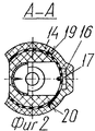
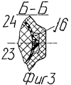
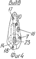
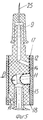
Для пояснения устройства одноразового шприца и его работы предлагается чертеж фиг. 1-5. На фиг. 1 изображен общий вид шприца в разрезе, в состоянии заводской поставки. Масштаб 4: 1, шприц объемом 2 миллилитра. На фиг. 2 - разрез А-А; на фиг. 3 - сечение Б-Б; на фиг. 4 - вид по стрелке В; на фиг. 5 - общий вид шприца в разрезе при попытке повторного набора жидкости. To explain the disposable syringe device and its operation, a drawing of FIG. 1-5. In FIG. 1 shows a General view of the syringe in the context, in a state of factory delivery. 4: 1 scale, 2 milliliter syringe. In FIG. 2 - section aa; in FIG. 3 - section BB; in FIG. 4 is a view along arrow B; in FIG. 5 is a sectional perspective view of a syringe when attempting to re-fill a fluid.
Предлагаемый одноразовый шприц состоит из цилиндра 1 с коническим выступом 2, поршня 3 со штоком 4, штыря 5 с полостью в торце в виде конического отверстия 6, образующего с коническим выступом 2 неразъемное соединение (или с помощью клея, или штифта, или холодной диффузионной сварки при помощи растворителя пластмассы дихлорэтана), бокового отверстия клапана 7 с иглой перфоратора 8, сообщающегося с полостью цилиндра 1, конического выступа 9 штыря 5, бокового отверстия 10, сообщающегося с полостями конического выступа 9 и иглы, ниппеля 11, надетого на штырь 5 с натягом и выполненного в виде резиновой трубки с поясами герметизации 12 и 13 по концам ее (герметизация обеспечивается или склеиванием концов трубки со штырем, или кольцами из 8-10 витков нити, или выполнением тугих окантовок на кромках трубки, или уплотнением кромок трубки установленным сверху кожухом), кожуха 14, облегающего ниппель 11 и имеющего со штырем 5 неразъемное соединение (или с помощью клея, или штифта 15, или растворения пластмассы дихлорэтаном, или напрессовкой) и снабженного желобом 16, накрывающим оба боковых отверстия 7 и 10 и переходящим в канавки 17 и 18, связывающими желоб с атмосферой. Кроме того, кожух 14 имеет неразъемные соединения с ниппелем 11 посредством клея в отверстиях 19 и 20, заборника жидкости 21, установленного на коническом выступе 9 в заводских условиях, снабженного всасывающей трубкой 22 и разделителем 23, в виде гибкой упругой нити, которая нарушает герметизацию бокового отверстия клапана 7 и одновременно удерживает ниппель 11 от втягивания в отверстие клапана от избыточного давления на ниппель при всасывании жидкости. Заборник жидкости 21 снабжен металлической юбкой 24 иглы для инъекции 25. Для наблюдения за выходом газовых пузырей ниппель изготовляется из достаточно прозрачного вида резины (такая резина применяется на пипетках, хирургических перчатках), прозрачными в достаточной степени должны быть штырь и кожух. The proposed disposable syringe consists of a cylinder 1 with a conical protrusion 2, a piston 3 with a rod 4, a pin 5 with a cavity in the end in the form of a conical hole 6, forming an integral connection with the conical protrusion 2 (either using glue, or a pin, or cold diffusion welding using a dichloroethane plastic solvent), a side opening of the valve 7 with a perforator needle 8 communicating with the cavity of the cylinder 1, a conical protrusion 9 of the pin 5, a side hole 10 communicating with the cavities of the conical protrusion 9 and the needle, nipple 11 worn on tyr 5 with an interference fit and made in the form of a rubber tube with sealing belts 12 and 13 at its ends (sealing is provided either by gluing the ends of the tube with a pin, or rings of 8-10 turns of thread, or by making tight edging on the edges of the tube, or by sealing the edges of the tube mounted on top of the casing), casing 14, fitting the nipple 11 and having an integral connection with the pin 5 (either with glue or a pin 15, or dissolving the plastic with dichloroethane, or pressing) and equipped with a groove 16 that covers both side openings 7 and 10 and passing into the grooves 17 and 18, connecting the gutter with the atmosphere. In addition, the
Работа одноразового шприца происходит следующим образом. Поршень 3 вводят в цилиндр 1 до упора и через трубку 22 всасывают жидкость. Разделитель 23, отделяя ниппель 11 от штыря, формирует канал, по которому жидкость перетекает из трубки всасывания 22 в отверстие клапана 7. Одновременно разделитель 23 препятствует втягиванию ниппеля 11 в полость отверстия клапана 7 под действием наружного избыточного давления, работая на изгиб, и потому обладает достаточной изгибной жесткостью, что предотвращает контакт ниппеля 11 с иглой перфоратора 8. Далее снимают заборник жидкости 21, извлекая разделитель 23 и устанавливают на его место иглу 25. При этом ниппель 11 за счет упругих сил плотно прилегает к штырю 5, герметизируя оба боковых отверстия 7 и 10. Далее в вертикальном положении производят вытеснение газовых пузырей и затем инъекцию, при этом ниппель 11 приподнимается, уходя в желоб 16 и пропускает жидкость из отверстия клапана 7 в боковое отверстие 10 и далее в иглу. Положение ниппеля 11 при инъекции показано условной линией на фиг. 3 и 5. После инъекции ниппель 11 закрывает отверстие клапана 7 и далее работает как обратный клапан, что не позволит повторно набрать жидкость. При попытке залить жидкость в цилиндр и извлечь для этого поршень создается максимальное разрежение в полости клапана 7 потому, что после первой инъекции между поршнем и ниппелем заперта жидкость и, следовательно, нет начальной воздушной подушки. В результате ниппель втягивается в отверстие клапана и лопается, накалываясь на иглу перфоратора. Если теперь попытаться вытеснить газовые пузыри, то жидкость через разрыв в ниппеле будет попадать в желоб, а затем по канавкам 17 и 18 вытекать наружу, не попадая в иглу. Если будет попытка с самого начала снять заборник жидкости и сразу установить иглу, а далее залить жидкость в цилиндр, то избыточное давление на ниппель будет меньше, чем в первом случае, поэтому оно и является определяющим при подборе толщины оболочки ниппеля. Это случай сухого цилиндра, когда между поршнем и ниппелем существует начальная воздушная подушка. The work of a disposable syringe is as follows. The piston 3 is inserted into the cylinder 1 until it stops, and liquid is sucked through the tube 22. The
Для защиты разделителя от умышленного перерезания в месте выше торца конического выступа 9, с целью превращения шприца в многоразовый заборник жидкости снабжен стальной юбкой, а чтобы разделитель нельзя было перерезать в зазоре между торцем конического выступа и приподнятым заборником жидкости, в нем расстояние от обреза юбки до торца конического выступа больше рабочей длины разделителя, т.е. его части, которая уходит под ниппель и далее в отверстие клапана. To protect the separator from deliberate cutting at a place above the end of the
Для предупреждения манипуляций с ниппелем, который можно оттянуть над боковыми отверстиями и таким образом превратить шприц в многоразовый, он закрыт кожухом, который нелегко разрушить. А поскольку кожух имеет точечные неразъемные соединения с ниппелем, то при снятии кожуха ниппель будет порван, и шприц выйдет из строя. To prevent manipulation of the nipple, which can be pulled over the side openings and thus turn the syringe into a reusable one, it is covered with a casing that is not easy to break. And since the casing has point-in-one fixed connections with the nipple, when removing the casing, the nipple will be torn, and the syringe will fail.
Эксперименты показали, что все узлы шприца работают стабильно, вне зависимости от объема шприца и скорости движения поршня. Конструкция проста и поддается автоматической сборке. Предлагаемый шприц полностью сохраняет технологию и производство всемирно известного шприца. При достаточном производстве и накоплении насадков можно сразу, в объеме одной страны, перейти на альтернативные шприцы. Experiments have shown that all nodes of the syringe are stable, regardless of the volume of the syringe and the speed of the piston. The design is simple and amenable to automatic assembly. The proposed syringe fully preserves the technology and production of the world famous syringe. With sufficient production and accumulation of nozzles, you can immediately, in the volume of one country, switch to alternative syringes.
Claims (2)
Priority Applications (1)
| Application Number | Priority Date | Filing Date | Title |
|---|---|---|---|
| RU98108556A RU2139103C1 (en) | 1998-04-27 | 1998-04-27 | One-time syringe |
Applications Claiming Priority (1)
| Application Number | Priority Date | Filing Date | Title |
|---|---|---|---|
| RU98108556A RU2139103C1 (en) | 1998-04-27 | 1998-04-27 | One-time syringe |
Publications (2)
| Publication Number | Publication Date |
|---|---|
| RU98108556A RU98108556A (en) | 1998-12-27 |
| RU2139103C1 true RU2139103C1 (en) | 1999-10-10 |
Family
ID=20205622
Family Applications (1)
| Application Number | Title | Priority Date | Filing Date |
|---|---|---|---|
| RU98108556A RU2139103C1 (en) | 1998-04-27 | 1998-04-27 | One-time syringe |
Country Status (1)
| Country | Link |
|---|---|
| RU (1) | RU2139103C1 (en) |
Citations (3)
| Publication number | Priority date | Publication date | Assignee | Title |
|---|---|---|---|---|
| FR2618075A1 (en) * | 1987-07-17 | 1989-01-20 | Assistance Publique | NON-REUSABLE HIGH SECURITY SYRINGE |
| WO1990003816A1 (en) * | 1988-10-03 | 1990-04-19 | Ewald Pickhard | Disposable injection device |
| RU2008933C1 (en) * | 1987-06-25 | 1994-03-15 | Агвен Медикал Корпорейшн Лимитед | Disposable syringe |
-
1998
- 1998-04-27 RU RU98108556A patent/RU2139103C1/en active
Patent Citations (3)
| Publication number | Priority date | Publication date | Assignee | Title |
|---|---|---|---|---|
| RU2008933C1 (en) * | 1987-06-25 | 1994-03-15 | Агвен Медикал Корпорейшн Лимитед | Disposable syringe |
| FR2618075A1 (en) * | 1987-07-17 | 1989-01-20 | Assistance Publique | NON-REUSABLE HIGH SECURITY SYRINGE |
| WO1990003816A1 (en) * | 1988-10-03 | 1990-04-19 | Ewald Pickhard | Disposable injection device |
Similar Documents
| Publication | Publication Date | Title |
|---|---|---|
| CN101347646B (en) | Spring launched needle safety clip | |
| FI110169B (en) | Drainage device for liquid media, especially for discharge in one stroke | |
| US6605073B1 (en) | Safety syringe | |
| KR940013553A (en) | Syringes with needle isolation features | |
| US7387616B2 (en) | Safe medical needle apparatus | |
| RU2483760C2 (en) | Syringe with deactivating mechanism | |
| KR101335979B1 (en) | Filter hub assembly for aspirating and injecting liquid medicine | |
| US5254093A (en) | Non-reusable hypodermic syringe | |
| ES2307319T3 (en) | PISTON AND TUBE ASSEMBLY FOR SYRINGE. | |
| US20120302992A1 (en) | Pneumatic injector | |
| US20110092902A1 (en) | Single use syringe | |
| RO115848B1 (en) | MEDICAL DEVICE, UNIT OF USE, WITH FRONTAL RETURN | |
| EA003501B1 (en) | Needle protecting arrangement | |
| KR101532413B1 (en) | Disposable syringe having safety filter function | |
| RU2139103C1 (en) | One-time syringe | |
| US5308328A (en) | Single-use syringe | |
| KR102193995B1 (en) | Injector and Blood collecting injection having stick injury prevention and reuse prevention fuction | |
| US2693184A (en) | Hypodermic syringe and aspirating ampoule thereof | |
| SU1762937A1 (en) | Disposable syringe | |
| RU2203689C2 (en) | Disposable syringe | |
| RU2858283C1 (en) | Disposable self-destructing syringe | |
| WO1995031236A1 (en) | A safety syringe | |
| RU242351U1 (en) | Self-destructing disposable syringe | |
| KR102365300B1 (en) | Filter needle used in combination with syringe | |
| SU1718963A1 (en) | Single use syringe |