CN1048983A - Hypodermic syringe - Google Patents
Hypodermic syringe Download PDFInfo
- Publication number
- CN1048983A CN1048983A CN90106671.0A CN90106671A CN1048983A CN 1048983 A CN1048983 A CN 1048983A CN 90106671 A CN90106671 A CN 90106671A CN 1048983 A CN1048983 A CN 1048983A
- Authority
- CN
- China
- Prior art keywords
- syringe
- syringe needle
- piston
- chamber
- shell
- Prior art date
- Legal status (The legal status is an assumption and is not a legal conclusion. Google has not performed a legal analysis and makes no representation as to the accuracy of the status listed.)
- Pending
Links
Images


Classifications
-
- A—HUMAN NECESSITIES
- A61—MEDICAL OR VETERINARY SCIENCE; HYGIENE
- A61M—DEVICES FOR INTRODUCING MEDIA INTO, OR ONTO, THE BODY; DEVICES FOR TRANSDUCING BODY MEDIA OR FOR TAKING MEDIA FROM THE BODY; DEVICES FOR PRODUCING OR ENDING SLEEP OR STUPOR
- A61M5/00—Devices for bringing media into the body in a subcutaneous, intra-vascular or intramuscular way; Accessories therefor, e.g. filling or cleaning devices, arm-rests
- A61M5/178—Syringes
- A61M5/31—Details
- A61M5/32—Needles; Details of needles pertaining to their connection with syringe or hub; Accessories for bringing the needle into, or holding the needle on, the body; Devices for protection of needles
- A61M5/3205—Apparatus for removing or disposing of used needles or syringes, e.g. containers; Means for protection against accidental injuries from used needles
- A61M5/321—Means for protection against accidental injuries by used needles
- A61M5/322—Retractable needles, i.e. disconnected from and withdrawn into the syringe barrel by the piston
-
- A—HUMAN NECESSITIES
- A61—MEDICAL OR VETERINARY SCIENCE; HYGIENE
- A61M—DEVICES FOR INTRODUCING MEDIA INTO, OR ONTO, THE BODY; DEVICES FOR TRANSDUCING BODY MEDIA OR FOR TAKING MEDIA FROM THE BODY; DEVICES FOR PRODUCING OR ENDING SLEEP OR STUPOR
- A61M5/00—Devices for bringing media into the body in a subcutaneous, intra-vascular or intramuscular way; Accessories therefor, e.g. filling or cleaning devices, arm-rests
- A61M5/178—Syringes
- A61M5/24—Ampoule syringes, i.e. syringes with needle for use in combination with replaceable ampoules or carpules, e.g. automatic
- A61M5/2422—Ampoule syringes, i.e. syringes with needle for use in combination with replaceable ampoules or carpules, e.g. automatic using emptying means to expel or eject media, e.g. pistons, deformation of the ampoule, or telescoping of the ampoule
- A61M5/2429—Ampoule syringes, i.e. syringes with needle for use in combination with replaceable ampoules or carpules, e.g. automatic using emptying means to expel or eject media, e.g. pistons, deformation of the ampoule, or telescoping of the ampoule by telescoping of ampoules or carpules with the syringe body
-
- A—HUMAN NECESSITIES
- A61—MEDICAL OR VETERINARY SCIENCE; HYGIENE
- A61M—DEVICES FOR INTRODUCING MEDIA INTO, OR ONTO, THE BODY; DEVICES FOR TRANSDUCING BODY MEDIA OR FOR TAKING MEDIA FROM THE BODY; DEVICES FOR PRODUCING OR ENDING SLEEP OR STUPOR
- A61M5/00—Devices for bringing media into the body in a subcutaneous, intra-vascular or intramuscular way; Accessories therefor, e.g. filling or cleaning devices, arm-rests
- A61M5/50—Devices for bringing media into the body in a subcutaneous, intra-vascular or intramuscular way; Accessories therefor, e.g. filling or cleaning devices, arm-rests having means for preventing re-use, or for indicating if defective, used, tampered with or unsterile
- A61M5/5013—Means for blocking the piston or the fluid passageway to prevent illegal refilling of a syringe
-
- A—HUMAN NECESSITIES
- A61—MEDICAL OR VETERINARY SCIENCE; HYGIENE
- A61M—DEVICES FOR INTRODUCING MEDIA INTO, OR ONTO, THE BODY; DEVICES FOR TRANSDUCING BODY MEDIA OR FOR TAKING MEDIA FROM THE BODY; DEVICES FOR PRODUCING OR ENDING SLEEP OR STUPOR
- A61M5/00—Devices for bringing media into the body in a subcutaneous, intra-vascular or intramuscular way; Accessories therefor, e.g. filling or cleaning devices, arm-rests
- A61M5/178—Syringes
- A61M5/31—Details
- A61M2005/3117—Means preventing contamination of the medicament compartment of a syringe
- A61M2005/3118—Means preventing contamination of the medicament compartment of a syringe via the distal end of a syringe, i.e. syringe end for mounting a needle cannula
- A61M2005/312—Means preventing contamination of the medicament compartment of a syringe via the distal end of a syringe, i.e. syringe end for mounting a needle cannula comprising sealing means, e.g. severable caps, to be removed prior to injection by, e.g. tearing or twisting
-
- A—HUMAN NECESSITIES
- A61—MEDICAL OR VETERINARY SCIENCE; HYGIENE
- A61M—DEVICES FOR INTRODUCING MEDIA INTO, OR ONTO, THE BODY; DEVICES FOR TRANSDUCING BODY MEDIA OR FOR TAKING MEDIA FROM THE BODY; DEVICES FOR PRODUCING OR ENDING SLEEP OR STUPOR
- A61M5/00—Devices for bringing media into the body in a subcutaneous, intra-vascular or intramuscular way; Accessories therefor, e.g. filling or cleaning devices, arm-rests
- A61M5/178—Syringes
- A61M5/31—Details
- A61M5/32—Needles; Details of needles pertaining to their connection with syringe or hub; Accessories for bringing the needle into, or holding the needle on, the body; Devices for protection of needles
- A61M5/3202—Devices for protection of the needle before use, e.g. caps
Landscapes
- Health & Medical Sciences (AREA)
- Engineering & Computer Science (AREA)
- Hematology (AREA)
- Anesthesiology (AREA)
- Biomedical Technology (AREA)
- Heart & Thoracic Surgery (AREA)
- Vascular Medicine (AREA)
- Life Sciences & Earth Sciences (AREA)
- Animal Behavior & Ethology (AREA)
- General Health & Medical Sciences (AREA)
- Public Health (AREA)
- Veterinary Medicine (AREA)
- Environmental & Geological Engineering (AREA)
- Infusion, Injection, And Reservoir Apparatuses (AREA)
Abstract
A kind of hypodermic syringe that is used for the injection inoculation agent comprises: a shell (1), a piston element (2) and the hollow pinhead (3) that can be held and can extend out from shell (1) by shell (1) fully that supports slidably in the shell (1).Syringe needle (3) is supported on the piston element (2), and in syringe shot process, shrinks in the shell (1).Syringe also is included in to be finished after the shot, and syringe needle (3) is enclosed in safety device (22,24) in the shell (1).
Description
The present invention relates to a kind of hypodermic syringe, particularly a kind of hypodermic syringe that has the contraction type syringe needle.The present invention can use aspect medical science or veterinary, and the practice is will describe the present invention in conjunction with this practical application in the back easily.But should be clear and definite, the present invention is not limited to the application scenario of being lifted.
To the care of the propagation of HIV (human immunodeficiency virus), a kind of main mode of propagation of having found this virus now is by contact or uses the syringe that has been infected by HIV (human immunodeficiency virus) along with in the world.
In traditional hypodermic syringe, syringe needle keeps exposed state after syringe uses.Therefore exist quilt with crossing the accidental probability of stabbing of syringe needle afterwards.If patient is the HIV carrier, then might cause aids infection virus.In addition because the syringe needle and any syringe that expose all have infected probability, therefore, exhausted syringe abandon the way that also may become a danger.
Another shortcoming of traditional hypodermic syringe is can be repeated at an easy rate to use.In the junkie of intravenous injection drug use, a syringe is shared by many people usually.This has just increased the probability of contact HIV (human immunodeficiency virus) greatly.If one of user is this virus carrier and infects syringe that then syringe will make all the other people infect this virus.
Syringe has been improved to its syringe needle later and can have shunk back.The example of this class syringe number has been open in 130088/88,14189/88 and 16234/88 the application in Australian patent application.The general employing of these the existing syringes mode identical with conventional syringe extended the syringe needle of a hollow at an end of cylindrical housing, and extends a piston element to promote to be supported on piston wherein at the other end.Said apparatus can be arranged on the piston so that can be connected the tail end of syringe needle when finishing a shot.So syringe needle can be drawn out of by retract piston from syringe shell, on the other hand, syringe needle is fixed on the device, and this device allows syringe needle to be drawn out of after a shot is finished.
In these existing devices, syringe needle keeps exposed state to move until constriction device after finishing a shot always.Therefore still exist syringe with crossing the accidental soon afterwards probability that touches syringe needle.And, owing to piston element being retracted after injection or starting needle fixture with retracting needle, the benefit that makes syringe needle be in the exposed state constriction device thereby enough time retracting needles might be neglected or not have to user after using has not just existed yet.
Therefore, one object of the present invention just provides a kind of hypodermic syringe that has a hypodermic needle that can shrink in the middle of syringe carries out a shot and reduces to minimum so that chance contacts the probability of injection needle.
The present invention also has a preferred purpose just to provide a kind ofly can not or to be difficult to reusable disposable hypodermic syringe.
Consider these, the invention provides a kind of hypodermic syringe that is used for the injection inoculation agent, comprising a shell, one is in piston mobile element among the shell, and one can be fully be held and extendible hollow pinhead by shell, in outside shell, syringe needle is fixed on the piston element and at syringe and finishes in the shot process and can shrink to advance in the shell.
Because syringe needle collapses into shell in injection process, so syringe there is no need to move to shrink syringe needle again.
This hypodermic syringe preferably also comprises safety device, after a shot is finished syringe needle is sealed in the shell.Piston element preferably includes the elongate rod that one one end has piston, and the backward end of elongate rod extends syringe needle, and vertical syringe needle passage wherein is communicated with, runs through whole bar and piston with the vertical passage of elongate rod.
Shell preferably includes one and has and be used for the longilineal main part of support piston movably, an elongated safety guard part, this guard shield partly has a front end and a syringe needle chamber that is used for holding syringe needle, also comprises one by the pin hole of syringe needle chamber through the front end of safety guard part.
Above-mentioned safety device can comprise that is positioned near and the projection in the syringe needle chamber near pin hole, from pin hole, extract out fully when syringe needle and to be used for the blockade needle front end when entering the syringe needle intracavity, when syringe needle is unfettered therein, syringe needle and pin hole are just not in linear relation, and the longitudinal axis of syringe needle departs from angle of the longitudinal axis of thin bar at this moment.
Safety device can comprise, perhaps can also comprise a protruding chamber that is arranged in the main part of shell end, and it is near finishing the cylinder chamber that holds piston after the injection and width greater than cylinder chamber.Movably film is separating both to be provided with one near the joint in cylinder chamber and protruding chamber or its, and piston can be removed this film when piston enters in the protruding chamber.Between film and the protruding chamber is interference fit, a shallow slot is arranged to help film being fixed and remained on the appropriate location on the wall in protruding chamber.Piston can also have a projection of extending to the direction of film, and it is positioned near the edge that closes on piston or its, uses this projection to make things convenient for removing of film.
Can also there be at least one outward extending barb to return in the cylinder chamber again after entering in the protruding chamber near the piston place to prevent piston.
Pin medicated cap can form with the front end monoblock type of safety guard part and can with its disengagement, front end is in the frangible portions that a weakness is arranged near pin medicated cap place, relies on it to twist off the pin medicated cap and front end is thrown off, and exposes part syringe needle wherein.
Piston element preferably includes at least one handle component, by being in or extending out near the side of the other end of thin bar, an elongated cannelure is arranged in shell, can allow this handle component or each handle component be extended out by shell.Outer wall extends along the edge of most at least this cannelure or each cannelure.
Following description relates more specifically to the various features of hypodermic syringe of the present invention.For ease of understanding the present invention, present invention is described with reference to accompanying drawing, wherein in most preferred embodiment this hypodermic syringe illustrated.Need be appreciated that hypodermic syringe of the present invention is not limited to illustrated in the accompanying drawings most preferred embodiment.
In the accompanying drawings:
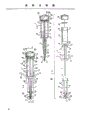
Figure 1A is the longitudinal sectional drawing of first most preferred embodiment of hypodermic syringe of the present invention;
Figure 1B is a longitudinal sectional drawing along the 1B section among Figure 1A;
Fig. 1 C is the exploded view of the hypodermic needle among Figure 1A and Figure 1B;
Fig. 2 A is hypodermic syringe among Figure 1A and Figure 1B longitudinal sectional drawing when syringe needle all stretches out before injection;
Fig. 2 B is a longitudinal sectional drawing along the 2B section among Fig. 2 A;
Fig. 2 C is the longitudinal sectional drawing of hypodermic syringe when finishing injection back syringe needle and all shrink among Figure 1A and Figure 1B;
Fig. 3 is the perspective view of the hypodermic syringe best hand-held in injection process among Figure 1A and Figure 1B;
Fig. 4 A is a part longitudinal sectional drawing of second most preferred embodiment of hypodermic syringe of the present invention; And
Fig. 4 B is the vertical view along the section 4B among Fig. 4 A.
At first see Figure 1A to Fig. 3, they have represented first most preferred embodiment of hypodermic syringe of the present invention.This hypodermic syringe comprises 1, one piston element 2 of a shell, and it is supported in the shell 1 by mode slidably, and the hypodermic needle 3 of a hollow, and it extends out from piston element 2 and becomes one with it.Piston element 2 and syringe needle 3 move together as an element.Figure 1A and 1B represent the situation in this hypodermic syringe syringe needle indentation before use shell 1.Can also see that this syringe is provided with the syringe needle 3 that stretches out, and syringe is filled with Inoculant in advance.
On the wall of safety guard 8, can drive a cannelure 15, handle component can be stretched out by shell 1 for each handle component 13.So just can be in the length travel of the outside of syringe shell 1 application piston element 2 and syringe needle 3.The length of groove 15 will be enough to allow syringe needle 3 to stretch out fully or shrink fully, and handle component 13 is preferably in when syringe needle is in each positions of above-mentioned two kinds of positions and all is positioned near the edge at groove 15 two ends.Circumferential wall 16 can be along the major part extension at the edge of each groove 15 at least.The existence of wall 16 makes syringe needle 3 be difficult to operation more when shrinking safety guard 8 fully.For making syringe compact more, handle component 13 can be made relatively thin cross section, make groove 15 can do very narrowly, thereby can limit the discrepancy of syringe needle 3.For guaranteeing that thin handle component 13 has sufficient intensity, can adopt high strength, low specific gravity material such as magnesium metal to make.Whole piston element 2 can be made with this material.
Bracing means can be housed to strengthen its rigidity on bar 11, anti-stopping bar 11 is crooked in the syringe use.Bracing means also has and helps guidance piston element 2 in shell 1.
For example, bracing means can comprise the web 17 that at least one is extended out by bar 11.Each web 17 can be come out and along its extending longitudinally by bar 11 horizontal expansions.Preferably extend four blocks of such webs 17 equidistantly from bar 11, the web 17 that the every block of web 17 on the bar 11 is adjacent differs 90 jiaos.Perhaps as shown in the figure two blocks of webs 17 that direction is opposite are only arranged.Web 17 preferably fuses with handle component 13, bar 11 and piston 12 and can move as an element with assurance piston element 2, and prevented the skew between bar 11, handle component 13 and piston 12 and its proper manipulation locations, or made offset minus to minimum.
At complete contraction state, syringe needle 3 can place the syringe needle chamber 9 of 8 li of safety guards.Pin hole 19 can reach the outside of shell 1 by the front end 10 of shell 1 with permission syringe needle 3 by extending out in the syringe needle chamber 9.Syringe needle 3 can extend the position shown in arrival Fig. 2 A and the 2B by the front end 10 to shell 1 by moving forward handle component (one or more), and this will make piston element 2 forward end move, and cause syringe needle 3 to reach the outside of shell 1 by pin hole 19.Moving forward of piston element 2 also makes piston 2 move to the direction away from film 26, thereby increased the volume of liquid storage space 23.Be retracting needle 3, handle component 13 moves away from the direction of front end 10 backward and has caused piston element 2 also to move towards the direction away from front end 10, syringe needle 3 just is withdrawn in the safety guard 8 like this, and piston 12 moves to film 26, has reduced the volume of liquid storage space 23.
Before using syringe, needle point 4 places the pin hole 19 of front end 10, and pin hole 19 can stop in a separate type pin medicated cap 5 that is fixed on removably on the front end 10.Perhaps, pin medicated cap 5 can constitute safety guard 8 part of the whole as shown in the Examples.Front end 10 can be equipped with one along the sheet 20 of turning round its horizontal expansion, staggered relatively.Be also noted that many fins are arranged on the outer surface of pin medicated cap 5, make finger can hold the pin medicated cap securely.Near turning round sheet 20 places an easily broken zone of weakness is arranged at front end 10, this is to be produced by the cannelure 21 around front end 10.
Be also noted that, a nozzle can be set simply seal to cover the outlet of pin hole 19.This seals best whole with front end 10 formations.Needle point 4 must at first be worn out this and seal, and syringe could use.Therefore, this seals and will quite approach so that worn out by syringe needle.Seal in order to wear out, piston element 2 must move forward and syringe needle 3 can be penetrated seal.
Taking away after pin medicated cap 5 exposes sub-fraction syringe needle 3, syringe needle 4 can insert in the Inoculant bottle with the required medicament of suction.When syringe needle 3 further stretches out from shell 1, liquid storage space 23 volume gain in the syringe and vacuum reduces, thus can be by syringe needle 3 and thin bar passage 14 with Inoculant suction storage space 23.Till when syringe needle 3 may extend to the syringe full of liquid or charges into the liquid of suitable dosage.
Subsequently, can go out liquid infusion by shell 1 is moved to the point of puncture of syringe needle 3.For this reason, as shown in Figure 3, also to hold the handle component 13 that extends out by shell 1, and allow palm or thumb withstand on the rear end of shell 1 with one or more fingers of a hands.By with palm or thumb rear end, the volume of liquid storage space 23 is reduced, thereby force liquid to be expelled to the injection site by thin bar passage 14 and syringe needle 3 to handle component 13 aspects pushing shell 1.In injection process, syringe needle 3 is withdrawn in the shell 1 gradually.
When injection finished, syringe needle 3 preferably all was withdrawn in the shell 1, and prevents reusing of syringe by safety device, or is difficult to reuse.This safety device can comprise a projection 22 near pin hole 19.Projection 22 can form the front end in syringe needle chamber 9 in the back of pin hole 19.Though the diameter of pin hole 19 is preferably in the space minimum that makes when syringe needle 3 is in wherein between pin hole 19 and the syringe needle 3, the diameter in syringe needle chamber 9 will be wider than the diameter of pin hole 19 relatively so that be provided with protruding 22 in pin hole 19 back.
When syringe needle 3 was fully retracted to 9 the insides, syringe needle chamber, needle point 4 was blocked by projection 22.For the ease of blocking needle point 4, syringe needle 3 can not be in line mobile with pin hole 19 when being tied.
By a kind of scheme, can there be skew in syringe needle 3, and promptly when syringe needle 3 was not tied, the general longitudinal axis with thin bar 11 of its longitudinal axis departed from an angle.This drift angle is less relatively, such as be 1.0 the degree about.When piston element 2 is positioned at cylinder chamber 7 the insides, the longitudinal axis of bar 11 before syringe uses with use in can be parallel and in line with the longitudinal axis of pin hole 19.When syringe needle 3 was arranged in pin hole 19 and suffers restraints, its longitudinal axis at first will be in line with the longitudinal axis of pin hole 19.Therefore, before syringe uses and in the middle of using, syringe needle 3 will be offset the deflection that overcomes existence, thereby makes the spring tension that remains on the syringe needle 3.If in the syringe needle 3 complete retracted needle chambeies 9,4 at needle point can be extracted out from hole 19, so that make syringe needle 3 no longer be subjected to the constraint in hole 19.Because have skew, syringe needle 3 will depart from the longitudinal axis in hole 19 again so that needle point 4 moves to beyond the axis of pin hole 19, and by syringe needle chamber 9 admittances of protruding 22 back.If attempt is stretched out syringe needle 3 again, needle point 4 will withstand projection 22, thereby prevents stretching out of syringe needle 3.The attempt that forces syringe needle 3 to move forward can cause needle point 4 to embed at least in part in the projection 22.
By another kind of scheme, the longitudinal axis of pin hole 19 can have a lateral shift with the longitudinal axis of thin bar 11, and syringe needle 3 needn't have skew again, because when syringe needle is in the pin hole, the deviation post of pin hole 19 can make syringe needle 3 produce skew.Therefore and the tension of the spring on the syringe needle 3 that produces has just guaranteed the state that can be in line again when syringe needle 3 is extracted out from pin hole 19.
Also will have a safety device to prevent after injection, some people of use syringe has a mind to expose the sub-fraction of syringe needle 3 and it can be reused, and perhaps makes this situation be difficult to take place.For this safety device is provided, main part 6 can comprise a protruding chamber 24 at its end.Protruding chamber 24 can be columnar, communicate with cylinder chamber 7 and diameter greater than cylinder chamber 7 diameters, and the longitudinal axis of its longitudinal axis and cylinder chamber 7 is in line.Therefore just producing one between cylinder chamber 7 and protruding chamber 24 is annular projection or wall 25 basically.A terminal available end cap 28 of shell 1 seals, thereby has sealed the opening in protruding chamber 24.
Piston 12 has outer wall 27, when syringe is in user mode and cylinder chamber 7 be sealed and matched.Outer wall 27 can be cut sth. askew into a frustum cone-shaped wall surface.The diameter of piston 12 preferably increases towards the direction of piston area 18.The outer wall 27 of piston 12 preferably is rubber-like at least, thereby can be compressed in cylinder chamber 7, keeps sealing state therein.Perhaps, outer wall 27 can have a cannelure and be used for holding a potted component that separates, and as an O shape ring, is sealed and matched to keep piston 12 and cylinder chamber 7.
Be in during needle point 4 beginning in the pin hole 19 syringe before use, piston 12 is positioned near film 26 places shown in Figure 1A or presses close to film 26.In this scheme, film 26 is supported by flexible member, it is contemplated that piston 12 can be pressed into film 26 in the protruding chamber 24 at least in part.When syringe needle 3 stretched out, piston 12 upwards promoted cylinder chamber 7 and arrives position shown in Fig. 2 A and the 2B.
In injection process, piston 12 returns to move to film 26.When injection finished, shown in Fig. 2 C, piston 12 compressing films 26 also made it mobile.When film 26 during interference fit, for helping moving film 26, is provided with a boss 29 on piston area 18 in protruding chamber 24.Boss 29 is substantially perpendicular to piston area 18 at least and leaves piston area 18 and stretches to film 26, and, can be located on or near the edge of piston area 18.Concentrate on the contact point of boss 29 and film 26 by the pressure that shrinks piston element 2 generations.This point makes compares with the power that acts on film 26 centers that near the edge of film 26 film 26 can be removed in the edge that only needs a less relatively masterpiece to be used for film 26.User can feel clearly that injection finishes, because when film 26 is removed, can feel that the moving resistance of handle component 13 descends.The removing of film 26 caused the pressure loss in the cylinder chamber 7 and syringe scrapped.In addition, when piston 12 entered protruding chamber 24, syringe needle 3 was also all extracted out from hole 19, enters in the syringe needle chamber 9, is blocked in protruding 22 back.
In some cases, syringe is preferably made and makes user be difficult to know when to inject end.So just can prevent (for example) thus the IDU person handles and uses syringe, prevents that syringe needle 3 from almost still keeping extension state to prevent to allow other people reuse this syringe when injection finishes.In front in the scheme of Miao Shuing, film 26 is supported by flexible member, for the syringe user, be difficult to know when piston 12 arrives this point, this is because film 26 can be removed by piston 12 at an easy rate, and does not also represent clear and definite " termination " point that the inoculation medicament is all finished by injection for piston element 2.Therefore, will be difficult to avoid piston 12 to shrink fully for the user, cross cylinder chamber 7, enter in the protruding chamber 24, and syringe needle 3 complete retraction syringe needle chambeies 9.
Because the diameter in protruding chamber 24 is greater than the diameter of cylinder chamber 7, therefore, piston 12 can extend from confined state when entering protruding chamber 24.The outer wall 27 of cutting sth. askew also helps to guide piston 12 to enter in the protruding chamber 24.This is because when piston 12 arrived annular projection 25, the shape of the stretching, extension of piston 12 and the outer wall of cutting sth. askew 27 thereof has played " drew " effect of going into protruding chamber 24 with piston 12.This effect that pulls back has guaranteed that further after syringe used, syringe needle 3 will all shrink unavoidably.
For guaranteeing that further piston 12 remains in the protruding chamber 24, a boss or a barb 30 that points to syringe needle 3 is set on the face of piston 12 at least, perhaps these boss or barb 30 can extend out from the every block of web 17 near piston 12.Barb 30 can have elasticity, and the substantial lateral extension, and when piston 12 was not constrained in the cylinder chamber 7, barb 30 was crossed the outer wall 27 of piston 12, shown in Fig. 1 C.Shown in Figure 1A, when piston 12 was in the cylinder chamber 7, barb 30 was at first to bar 11 deflections.When piston 12 entered protruding chamber 24, barb 30 laterally outwards stretched.If attempt piston 12 is withdrawn in the cylinder chamber 7, then barb 30 will be stuck in annular wall 25 places.
Figure 1A extremely hypodermic syringe shown in Figure 3 can use in the following manner:
A) syringe is furnished with the syringe needle 3 that is enclosed in the safety guard 8 to prevent contact and therefore contaminated pinhead 3.
B) back out pin medicated cap 5, expose needle point 4.For example expose syringe needle 3 about 6mm to realize extracting the purpose of Inoculant.Remove pin medicated cap 5 and can find out also whether syringe had used or quilt was employed.
C) by forward end 10 moving handle elements 13, expose syringe needle 3,, prepare injection Inoculant suction liquid storage space 23 to its whole active lengths.After the enough medicament of suction, the same piston 12 that starts with usual manner enters compressive state to drive air away.
D) entering for patient in the process of injection, safety guard 8 is delivered to a certain position with syringe needle 3, on this position when injection finishes front end 10 touch muscle.Because film 26 must remove, therefore, carry when finishing in a shot, can feel tangible resistance, allow user know that medicament has been injected and finish.
E) by continuing pushing, when feeling resistance above-mentioned, syringe has just been scrapped, and syringe can not use and be safe.Syringe needle 3 all is withdrawn in the safety guard 8, and the pressure of cylinder chamber 7 disappears.Make the people can't touch syringe needle 3 in this way, because it is when it leaves patient's muscle, covered firmly.
Second most preferred embodiment of the present invention is shown in Fig. 4 A and 4B.This embodiment is applicable to deep intramuscular injection, but the purposes of others is identical with first embodiment.
In first embodiment, syringe needle 3 is gradually in the indentation shell 1 in injection process, so that make needle point 4 when injection finishes, be exposed to the outside, and, only be outside before above-mentioned safety device is with syringe needle 3 whole suction shells 1, being exposed to.Therefore being unsuitable for syringe must penetrate the deep intramuscular injection that fat deposit enters muscle dearly.For making the present invention be adapted to this application, second embodiment provides a kind of elongated pin medicated cap 105, and to allow to take away after the pin medicated cap 105, the length of the syringe needle 103 that at first exposes is longer.Pin medicated cap 105 also can have one and turn round sheet 120, and can be the same with first embodiment, constitutes an integral body with safety guard 108, and an easily broken district that exists with the form of endless groove 121 is arranged on the wall of safety guard 108.
Because before injection end and syringe needle 103 whole withdrawals, syringe needle 103 has a longer part to be exposed, therefore, syringe needle 103 can deeper thrust muscle.Because syringe needle 103 is longer relatively than the syringe needle among first embodiment 3, so main part 106 is also long so that shell 101 can hold long syringe needle 103 than the main part among first embodiment.Particularly the protruding chamber (not shown) of main part 106 needs long enough so that piston 102 fully shrinks.For ease of using the syringe in the present embodiment, handle component 103 can be longitudinally towards the direction lengthening of end cap 128, thereby make finger can easily catch handle component 113.
Shell 1,101 can be made two parts, to make things convenient for the insertion of piston element 2,102 and syringe needle 3,103 wherein.For example safety guard 8,108 can be opened making in 6,106 minutes with main part.Therefore, piston element 2,102 can fixedly insert in the main part 6,106 to form a complete shell 1,101 before the safety guard 8,108.Film 26 and any flexible member can insert by the opening in protruding chamber 24.28,128 of end caps can be enclosed in above-mentioned parts the inside.
In another program, shell 1,101 and make an integral member by the piston element 2,102 that chute on the safety guard 8,108 5,105 or the opening by main part 6,106 insert in the shell 1.
The various parts of this syringe utilize traditional injection molding to be easy to make, and generally make with plastic material.For example, main part 6,106 and safety guard 8,108 usefulness high strength polystyrene compression moldings, piston element 2,102 and end cap 28,128 usefulness polypropylene, film 26 usefulness acrylonitrile-butadiene-styrene terpolymer (ABS) compression moldings.
Syringe of the present invention can be contained in one and be used for enabling prematurely in the container of syringe safe device.As previously mentioned, be also noted that syringe will inject the Inoculant of doses in advance.Because syringe needle will extend to whole active lengths from syringe shell, then need the elongated pin medicated cap of a syringe needle that holds to stretch out.In addition, this syringe is identical with the foregoing description.
Because when syringe finished a shot, syringe needle all was withdrawn in the shell, therefore, hypodermic syringe of the present invention uses and handles safer.After a shot is finished, there is no need then to start the syringe needle constriction device and eliminate syringe and use the back syringe needle to be exposed to outer probability.In addition, preferablely be, hypodermic syringe of the present invention can only use once, thereby the syringe that has guaranteed contaminated mistake can not reuse.
Understand, the improvement that this syringe is done and augmenting is with the scope of the present invention that does not break away from defined in the appending claims here.
Claims (14)
1, a kind of hypodermic syringe that is used for the injection inoculation agent, comprise a shell, a piston element that is fixed in slidably in the shell, one can be accommodated in the shell and the extensible hollow pinhead that comes out fully, it is characterized in that, syringe needle is supported on the piston element, and shrinks in the shell in syringe shot process.
2,, also comprise finishing being used for after the shot syringe needle is sealed in safety device in the shell according to the described hypodermic syringe of claim 1.
3, according to claim 1 or 2 described hypodermic syringes, it is characterized in that piston element comprises that one has a piston at the one end, the elongate rod that has syringe needle to extend out from the other end, wherein syringe needle has one to communicate with thin bar vertical passage, runs through the vertical passage of whole bar and piston.
4, according to the described hypodermic syringe of claim 3, it is characterized in that, shell comprises an elongated body part, wherein there is one to be used for the cylinder chamber of support piston slidably, an elongated safety guard part that has front end and be used for holding the syringe needle chamber of syringe needle, and a pin hole that runs through safety guard part front end from the syringe needle chamber.
5, hypodermic syringe according to claim 4, it is characterized in that, safety device comprises a projection that is arranged in the syringe needle chamber near pin hole, when syringe needle by fully from pin hole suction syringe needle chamber the time, this projection is with the tip sealing of syringe needle, when syringe needle was unfettered therein, syringe needle and pin hole no longer were in line.
According to the described hypodermic syringe of claim 5, it is characterized in that 6, when syringe needle was unfettered, its longitudinal axis departed from an angle with the longitudinal axis of thin bar.
According to the described hypodermic syringe of claim 4 to 6, it is characterized in that 7, safety device comprises a protruding chamber that is arranged in the main part of shell end, this protruding chamber is connected with the cylinder chamber that holds piston after finishing injection, and diameter is greater than the cylinder chamber diameter.
8, according to the described hypodermic syringe of claim 7, it is characterized in that, the junction in cylinder chamber and protruding chamber or near, have a removable film 26 to be used for protruding chamber and cylinder chamber isolating seal, when piston entered protruding chamber, this film was removed by piston.
9, described according to Claim 8 hypodermic syringe is characterized in that, film and protruding chamber are interference fit, a shallow slot is arranged to help the film location and to remain on the appropriate location on the wall of protruding chamber.
According to the described hypodermic syringe of claim 9, it is characterized in that 10, a projection of extending to the direction of film is arranged on piston, this projection be positioned at piston periphery or near, be used for making removing of film more convenient.
11, any one described hypodermic syringe in 10 according to Claim 8 is characterized in that at least one outward extending barb is arranged, to prevent piston after entering protruding chamber, to the moving cylinder chamber that enters of travelling backwards near piston.
12, according to the described hypodermic syringe of claim 4, it is characterized in that, the front end of pin medicated cap and safety guard part constitutes an integral body, and can throw off with front end, near pin medicated cap place one section weak frangible portions is arranged at front end, thereby the pin medicated cap can be twisted off, and is separated with front end, exposes a part of syringe needle wherein.
13, according to the described hypodermic syringe of claim 4, it is characterized in that, piston element comprises one at least by thin bar backward end place or near horizontal expansion is come out it handle component, in shell, have an elongated cannelure with allow should or each handle component stretch out from shell.
14, according to the described hypodermic syringe of claim 13, it is characterized in that, outer wall along most at least should or the edge of each cannelure extend.
Applications Claiming Priority (2)
| Application Number | Priority Date | Filing Date | Title |
|---|---|---|---|
| AUPJ5195 | 1989-07-12 | ||
| AUPJ519589 | 1989-07-12 |
Publications (1)
| Publication Number | Publication Date |
|---|---|
| CN1048983A true CN1048983A (en) | 1991-02-06 |
Family
ID=3774052
Family Applications (1)
| Application Number | Title | Priority Date | Filing Date |
|---|---|---|---|
| CN90106671.0A Pending CN1048983A (en) | 1989-07-12 | 1990-07-12 | Hypodermic syringe |
Country Status (8)
| Country | Link |
|---|---|
| US (1) | US5226893A (en) |
| JP (1) | JPH0649073B2 (en) |
| CN (1) | CN1048983A (en) |
| GB (1) | GB2239608B (en) |
| IE (1) | IE902498A1 (en) |
| IL (1) | IL95040A (en) |
| IN (1) | IN178741B (en) |
| WO (1) | WO1991000747A1 (en) |
Cited By (3)
| Publication number | Priority date | Publication date | Assignee | Title |
|---|---|---|---|---|
| CN104321101A (en) * | 2012-01-31 | 2015-01-28 | 株式会社资生堂 | Injection devices |
| CN104755119A (en) * | 2012-10-19 | 2015-07-01 | 安进公司 | Improved auto-injector |
| CN109552766A (en) * | 2019-01-13 | 2019-04-02 | 谢双 | Medical acupuncture needle ejector |
Families Citing this family (23)
| Publication number | Priority date | Publication date | Assignee | Title |
|---|---|---|---|---|
| EP0637256B1 (en) * | 1992-04-21 | 2002-03-13 | Eastland Technology Australia Pty. Ltd. | An improved parenteral device |
| US5836921A (en) | 1993-08-23 | 1998-11-17 | Mahurkar; Sakharam D. | Hypodermic needle assembly |
| US5643222A (en) * | 1993-08-23 | 1997-07-01 | Mahurkar; Sakharam D. | Hypodermic needle assembly |
| CA2174952A1 (en) * | 1993-10-26 | 1995-05-04 | Maxwell Edmund Whisson | Syringe or like parenteral device |
| AU676783B2 (en) * | 1993-10-26 | 1997-03-20 | Eastland Medical Systems Limited | Syringe or like parenteral device |
| US5709667A (en) * | 1995-05-17 | 1998-01-20 | Carilli; Brian D. | Hypodermic needle protection system |
| GB2307643A (en) * | 1995-12-02 | 1997-06-04 | Epsom Glass Ind Ltd | Pre-fillable disposable syringe |
| US6958055B2 (en) * | 1998-09-04 | 2005-10-25 | Nmt Group Plc | Retractable needle syringe including a sheath and an intravenous adapter |
| GB2359754B (en) | 2000-03-03 | 2004-04-28 | Nmt Group Plc | Needle sheath |
| US6530903B2 (en) | 2000-02-24 | 2003-03-11 | Xiping Wang | Safety syringe |
| US20060264840A1 (en) * | 2005-05-09 | 2006-11-23 | Daniel Thayer | Syringe |
| US7972301B2 (en) | 2006-04-03 | 2011-07-05 | Safeshot Technologies, Llc | Safety needle syringe braking system |
| US20070250003A1 (en) * | 2006-04-03 | 2007-10-25 | Bare Rex O | Fluid activated retractable safety syringe |
| US7806858B2 (en) * | 2006-04-19 | 2010-10-05 | Safeshot Technologies, Llc | Vacuum actuated small volume syringe |
| US8152762B2 (en) * | 2006-04-20 | 2012-04-10 | Safeshot Technologies, Llc | Plunger activated vacuum release mechanism for a syringe |
| US8398601B2 (en) * | 2006-11-06 | 2013-03-19 | Safeshot Technologies, Llc | Puncturable membrane for safety syringe |
| US20080114307A1 (en) * | 2006-11-06 | 2008-05-15 | Jeffrey Smith | Puncturable membrane for safety syringe |
| US7972300B2 (en) * | 2006-05-05 | 2011-07-05 | Safeshot Technologies, Llc | Syringe |
| US8088104B2 (en) * | 2006-05-24 | 2012-01-03 | Safeshot Technologies, Llc | Syringe |
| US8617112B2 (en) * | 2007-03-30 | 2013-12-31 | Terumo Kabushiki Kaisha | Indwelling needle assembly |
| US8095870B2 (en) * | 2007-06-06 | 2012-01-10 | Oracle International Corporation | Extensible document transformation language: an innovative way of generating business document and report |
| US8277422B2 (en) | 2010-07-23 | 2012-10-02 | Safeshot Technologies, Llc | Multi-chambered retractable safety syringe |
| TWI689326B (en) | 2014-08-06 | 2020-04-01 | 加拿大商複製細胞生命科學公司 | Injection devices |
Family Cites Families (24)
| Publication number | Priority date | Publication date | Assignee | Title |
|---|---|---|---|---|
| US1555282A (en) * | 1924-12-23 | 1925-09-29 | George N Hein | Hypodermic-syringe construction |
| US3066671A (en) * | 1959-10-27 | 1962-12-04 | Milton J Cohen | Disposable additive container |
| GB932285A (en) * | 1961-06-08 | 1963-07-24 | Boehringer & Soehne Gmbh | Injection ampoule |
| US3587575A (en) * | 1969-09-15 | 1971-06-28 | Lichtenstein Eric Stefan | Self-contained, moving needle syringe with hydraulic safety lock |
| US3722512A (en) * | 1970-08-05 | 1973-03-27 | Lincoln Labor Inc | One hand injector |
| US3906947A (en) * | 1970-12-15 | 1975-09-23 | Harold S Cloyd | Syringe |
| US3841329A (en) * | 1972-09-11 | 1974-10-15 | Upjohn Co | Compact syringe |
| GB2064964A (en) * | 1979-12-12 | 1981-06-24 | Nat Res Dev | Syringe |
| AU566250B2 (en) * | 1983-10-19 | 1987-10-15 | Locali Pty. Ltd. | Syringe in which needle connects to plunger |
| US4681567A (en) * | 1986-04-03 | 1987-07-21 | Masters Edwin J | Syringe with safety sheath |
| US4795432A (en) * | 1987-02-19 | 1989-01-03 | Karczmer Claude M | Shield assembly for hypodermic injection devices |
| US4832696A (en) * | 1987-03-05 | 1989-05-23 | Luther Medical Products, Inc. | Assembly of needle and protector |
| US4770655A (en) * | 1987-03-13 | 1988-09-13 | Habley Medical Technology Corporation | Disease control syringe having a retractable needle |
| US4767413A (en) * | 1987-04-20 | 1988-08-30 | Habley Medical Technology Corporation | Dental syringe having an automatically retractable needle |
| DE3852885T2 (en) * | 1987-04-22 | 1995-05-18 | Maxwell Edmund Whisson | PARENTERAL ARRANGEMENT. |
| US4747831A (en) * | 1987-04-29 | 1988-05-31 | Phase Medical, Inc. | Cannula insertion set with safety retracting needle |
| CH673775A5 (en) * | 1987-07-10 | 1990-04-12 | Jacques Verlier | |
| US4950252A (en) * | 1987-11-02 | 1990-08-21 | Luther Medical Products, Inc. | Single hand actuated locking safety catheter and method of use |
| US4813426A (en) * | 1987-11-09 | 1989-03-21 | Habley Medical Technology Corporation | Shielded safety syringe having a retractable needle |
| WO1989004681A1 (en) * | 1987-11-18 | 1989-06-01 | Catch 522 Pty. Limited | Single use syringe |
| US4938745A (en) * | 1988-02-25 | 1990-07-03 | Sagstetter William E | Needle guard with visual confirmation of lock |
| US4892521A (en) * | 1988-08-03 | 1990-01-09 | Lincoln Mills, Inc. | Protective cover for hypodermic needle |
| US4909793A (en) * | 1988-08-29 | 1990-03-20 | Vining Herbert C | Intravenous catheter apparatus with retractable stylet |
| US4917669A (en) * | 1989-02-08 | 1990-04-17 | Safetyject | Catheter inserter |
-
1990
- 1990-07-09 WO PCT/AU1990/000295 patent/WO1991000747A1/en active Application Filing
- 1990-07-09 US US07/663,918 patent/US5226893A/en not_active Expired - Fee Related
- 1990-07-09 JP JP2509324A patent/JPH0649073B2/en not_active Expired - Lifetime
- 1990-07-10 IE IE249890A patent/IE902498A1/en unknown
- 1990-07-11 IN IN560MA1990 patent/IN178741B/en unknown
- 1990-07-11 IL IL9504090A patent/IL95040A/en not_active IP Right Cessation
- 1990-07-12 CN CN90106671.0A patent/CN1048983A/en active Pending
-
1991
- 1991-03-11 GB GB9105090A patent/GB2239608B/en not_active Expired - Fee Related
Cited By (5)
| Publication number | Priority date | Publication date | Assignee | Title |
|---|---|---|---|---|
| CN104321101A (en) * | 2012-01-31 | 2015-01-28 | 株式会社资生堂 | Injection devices |
| CN104321101B (en) * | 2012-01-31 | 2018-02-06 | 株式会社资生堂 | Injection device |
| CN104755119A (en) * | 2012-10-19 | 2015-07-01 | 安进公司 | Improved auto-injector |
| CN109552766A (en) * | 2019-01-13 | 2019-04-02 | 谢双 | Medical acupuncture needle ejector |
| CN109552766B (en) * | 2019-01-13 | 2019-12-13 | 山东中医药大学 | medical acupuncture needle ejector |
Also Published As
| Publication number | Publication date |
|---|---|
| IL95040A (en) | 1994-11-11 |
| GB2239608A (en) | 1991-07-10 |
| GB2239608B (en) | 1993-01-20 |
| JPH0649073B2 (en) | 1994-06-29 |
| WO1991000747A1 (en) | 1991-01-24 |
| IN178741B (en) | 1997-06-14 |
| GB9105090D0 (en) | 1991-05-01 |
| US5226893A (en) | 1993-07-13 |
| JPH04500621A (en) | 1992-02-06 |
| IE902498A1 (en) | 1991-02-13 |
Similar Documents
| Publication | Publication Date | Title |
|---|---|---|
| CN1048983A (en) | Hypodermic syringe | |
| CN1137240A (en) | Hypodermic syringe with retractable needle mount | |
| CN101347646B (en) | Spring launched needle safety clip | |
| EP1765438B1 (en) | Single-use syringe | |
| CN1230216C (en) | Disposable syringe | |
| US5085640A (en) | Non-reusable medical needle apparatus | |
| US5180369A (en) | Self destructive safety syringe | |
| KR20040103930A (en) | Intradermal injector | |
| CN1635919A (en) | Retractable needle medical device for injecting fluid from a pre-filled cartridge | |
| CN1867368A (en) | Injection device comprising a needle cover | |
| CN1541124A (en) | Prefillable intradermal delivery device | |
| CN1531446A (en) | Intradermal needle | |
| WO2014184321A2 (en) | Syringes | |
| CN1429631A (en) | Medical needle assembly | |
| IL114093A (en) | Blunt cannula construction for multiple applications | |
| MXPA06001075A (en) | Syringe assembly having disabling mechanism. | |
| KR102272644B1 (en) | Disposable safety needle and injection device comprising the same | |
| CN103127589A (en) | Safety self-destruction syringe | |
| WO2006081460A2 (en) | Low-cost non-reusable and anti-needlestick enhancements to disposable syringes | |
| US6941983B2 (en) | Syringe guide | |
| KR100673284B1 (en) | One-use retracting syringe with positive needle retention | |
| AU624979B2 (en) | Hypodermic syringe | |
| CN2612386Y (en) | Self-destruction type disposable safe syringe without residue | |
| KR20180016745A (en) | Needle unit for syringe | |
| CN1827185A (en) | Intracutaneous injection device capable of being filled with liquor beforehand |
Legal Events
| Date | Code | Title | Description |
|---|---|---|---|
| C06 | Publication | ||
| PB01 | Publication | ||
| C10 | Entry into substantive examination | ||
| SE01 | Entry into force of request for substantive examination | ||
| C01 | Deemed withdrawal of patent application (patent law 1993) | ||
| WD01 | Invention patent application deemed withdrawn after publication |