RU2136373C1 - Centrifugal concentrator - Google Patents
Centrifugal concentrator Download PDFInfo
- Publication number
- RU2136373C1 RU2136373C1 RU98110120/03A RU98110120A RU2136373C1 RU 2136373 C1 RU2136373 C1 RU 2136373C1 RU 98110120/03 A RU98110120/03 A RU 98110120/03A RU 98110120 A RU98110120 A RU 98110120A RU 2136373 C1 RU2136373 C1 RU 2136373C1
- Authority
- RU
- Russia
- Prior art keywords
- inclined shaft
- cone
- bowl
- shaft
- shaped bowl
- Prior art date
Links
- 239000000463 material Substances 0.000 claims abstract description 12
- 230000001105 regulatory effect Effects 0.000 claims 1
- 229910052500 inorganic mineral Inorganic materials 0.000 abstract description 18
- 239000011707 mineral Substances 0.000 abstract description 18
- 238000000926 separation method Methods 0.000 abstract description 10
- 239000012141 concentrate Substances 0.000 abstract description 8
- 230000005484 gravity Effects 0.000 abstract description 4
- CWYNVVGOOAEACU-UHFFFAOYSA-N Fe2+ Chemical compound [Fe+2] CWYNVVGOOAEACU-UHFFFAOYSA-N 0.000 abstract description 3
- 238000000034 method Methods 0.000 abstract description 3
- 239000010432 diamond Substances 0.000 abstract description 2
- 238000005065 mining Methods 0.000 abstract description 2
- 229910000510 noble metal Inorganic materials 0.000 abstract description 2
- 238000007599 discharging Methods 0.000 abstract 2
- 230000000712 assembly Effects 0.000 abstract 1
- 238000000429 assembly Methods 0.000 abstract 1
- 230000000694 effects Effects 0.000 abstract 1
- 239000000126 substance Substances 0.000 abstract 1
- 239000002245 particle Substances 0.000 description 8
- XLYOFNOQVPJJNP-UHFFFAOYSA-N water Substances O XLYOFNOQVPJJNP-UHFFFAOYSA-N 0.000 description 4
- 238000009825 accumulation Methods 0.000 description 2
- 238000000605 extraction Methods 0.000 description 2
- 238000005406 washing Methods 0.000 description 2
- 230000001133 acceleration Effects 0.000 description 1
- 230000005540 biological transmission Effects 0.000 description 1
- 230000015572 biosynthetic process Effects 0.000 description 1
- 238000004140 cleaning Methods 0.000 description 1
- 238000011010 flushing procedure Methods 0.000 description 1
- PCHJSUWPFVWCPO-UHFFFAOYSA-N gold Chemical compound [Au] PCHJSUWPFVWCPO-UHFFFAOYSA-N 0.000 description 1
- 239000010931 gold Substances 0.000 description 1
- 229910052737 gold Inorganic materials 0.000 description 1
- 239000008187 granular material Substances 0.000 description 1
- 229910052751 metal Inorganic materials 0.000 description 1
- 239000002184 metal Substances 0.000 description 1
- 239000000203 mixture Substances 0.000 description 1
- 238000005457 optimization Methods 0.000 description 1
- 230000003534 oscillatory effect Effects 0.000 description 1
- 239000010970 precious metal Substances 0.000 description 1
- 239000004576 sand Substances 0.000 description 1
- 239000007787 solid Substances 0.000 description 1
Images
Landscapes
- Centrifugal Separators (AREA)
Abstract
Description
Изобретение относится к горнодобывающей технике, в частности к устройствам для обогащения руд и песков, содержащих алмазы, цветные и благородные металлы, преимущественно для разделения по плотности тонкоизмельченных материалов в центробежном поле. The invention relates to mining equipment, in particular to a device for the beneficiation of ores and sand containing diamonds, non-ferrous and noble metals, mainly for density separation of finely ground materials in a centrifugal field.
Известен концентратор для отделения золота, включающий станину, подвешенный на ней разделитель в форме чаши с возможностью совершения вращательных и колебательных движений, привод, питающее устройство (патент США N 2256504, кл. 209-437 - аналог). A known hub for separating gold, including a bed, a separator suspended in it in the form of a bowl with the possibility of performing rotational and oscillatory movements, a drive, a feeding device (US patent N 2256504, CL 209-437 - analogue).
К недостаткам концентратора относится ненадежность конструкции, невозможность регулирования величины и оптимизации центробежных сил для разделения минералов по плотности. The disadvantages of the concentrator include the unreliability of the design, the inability to control the magnitude and optimization of centrifugal forces for the separation of minerals by density.
Известен центробежный концентратор, включающий конусообразную чашу, монтированную на наклонном валу с возможностью вращения вокруг вертикальной оси, питающее и разгрузочное приспособления, стопор, не позволяющий конусообразной чаше совершать вращательное движение вокруг собственной оси, но не препятствующий движению вокруг вертикальной оси (SU 899125A, 23.01.82, В 03 В 5/32 - прототип). A centrifugal concentrator is known, including a cone-shaped bowl mounted on an inclined shaft with the possibility of rotation around a vertical axis, feeding and unloading devices, a stopper that does not allow the cone-shaped bowl to rotate around its own axis, but does not impede movement around the vertical axis (SU 899125A, 23.01. 82, 03B 5/32 - prototype).
Недостатками аппарата являются его недостаточная надежность в работе и невозможность получать заданную степень сокращения исходного материала, что не позволяет выделять концентраты с высоким содержанием полезных компонентов. The disadvantages of the apparatus are its lack of reliability in the work and the inability to obtain a given degree of reduction of the source material, which does not allow to allocate concentrates with a high content of useful components.
Техническая задача изобретения - повышение надежности работы концентратора, обеспечение снижения потерь полезных минералов путем эффективного регулирования параметров разделения, упрощения наладки его узлов, в частности узла загрузки и выгрузки уловленных полезных минералов. The technical task of the invention is to increase the reliability of the concentrator, to reduce the loss of useful minerals by effectively adjusting the separation parameters, simplifying the adjustment of its nodes, in particular the node for loading and unloading the caught useful minerals.
Изобретение позволяет более эффективно разделить смеси материалов, содержащих минералы цветных и благородных металлов и пустой породы. The invention allows more efficient separation of mixtures of materials containing non-ferrous and precious metal minerals and gangue.
Технический результат, который может быть получен при осуществлении изобретения, заключается как в повышении извлечения полезных минералов, так и в повышении качества готового продукта. The technical result that can be obtained by carrying out the invention is both to increase the extraction of useful minerals and to improve the quality of the finished product.
Более высокие технологические показатели достигаются тем, что центробежный концентратор, включающий конусообразную чашу, монтированную на наклонном валу с возможностью вращения вокруг вертикальной оси, питающее и разгрузочное приспособления, стопор не позволяющий конусообразной чаше совершать вращательное движение вокруг собственной оси, но не препятствующий движению вокруг вертикальной оси, по изобретению наклонный вал в нижней части установлен шарнирно, а в верхней части наклонного вала установлен подшипник и входящий в него штифт, жестко связанный с приводным валом через закрепленное на нем соединительное устройство с пазом для регулирования угла наклона, причем стопор закреплен в нижней части наклонного вала, концентратор снабжен разгрузочным приспособлением для тяжелой фракции, конусообразная чаша снабжена специальной внутренней поверхностью, выбираемой в зависимости от концентрации полезных компонентов в обогащаемом материале. Higher technological performance is achieved by the fact that a centrifugal concentrator, including a cone-shaped bowl mounted on an inclined shaft with the possibility of rotation around the vertical axis, feeding and unloading devices, a stopper that does not allow the cone-shaped bowl to rotate around its own axis, but not preventing movement around the vertical axis , according to the invention, the inclined shaft in the lower part is pivotally mounted, and in the upper part of the inclined shaft there is a bearing and the shafts included in it t, rigidly connected to the drive shaft through a connecting device fixed to it with a groove for adjusting the angle of inclination, with the stopper fixed at the bottom of the inclined shaft, the concentrator equipped with a discharge device for the heavy fraction, the cone-shaped bowl is equipped with a special inner surface, selected depending on the concentration of useful components in the enriched material.
Конусообразная чаша, монтированная с жесткой фиксацией в определенном положении, после совершения оборота вокруг вертикальной оси сообщает своей поверхностью резким толчок разделяемому материалу внутри чаши, благодаря чему частицы разделяемого материала приобретают высокое начальное ускорение и разгоняются до необходимой скорости. A cone-shaped bowl mounted with rigid fixation in a certain position, after making a revolution around the vertical axis, gives its surface a sharp push to the material to be separated inside the bowl, due to which the particles of the material to be separated acquire a high initial acceleration and accelerate to the required speed.
В результате движения конусообразной чаши, закрепленной на наклонном валу, вокруг вертикальной оси на разделяемый материал воздействуют переменные по величине и направлению силы, обеспечивающие эффективную дезинтеграцию и разделение минеральных частиц по плотности. As a result of the movement of a cone-shaped bowl fixed on an inclined shaft around a vertical axis, the material to be separated is affected by variables in magnitude and direction of force, which ensure effective disintegration and separation of mineral particles by density.
С целью более полного улавливания и концентрирования полезных минералов чаша имеет специальную внутреннюю поверхность. In order to more fully capture and concentrate useful minerals, the bowl has a special inner surface.
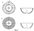
Для доводочных операции по перечистке гравитационных концентратов внутренняя поверхность имеет восемь канавок, отстающих друг от друга на 45o, которые проходят от верхнего края чаши до днища дугами, причем конец каждой дуги у днища смещен относительно начала дуги у верхнего края чаши на 180o. Глубина канавки соответствует крупности частиц полезного минерала и составляет 2-4 мм (фиг. 2А). Тяжелые частицы полезных минералов, коснувшиеся боковой поверхности чаши, попадают в канавки и транспортируются к днищу чаши, при этом предотвращается их случайный выброс с легкой фракцией.For finishing operations on cleaning gravity concentrates, the inner surface has eight grooves that are 45 o behind each other, which extend from the upper edge of the bowl to the bottom by arcs, and the end of each arc at the bottom is 180 ° offset from the beginning of the arc at the top of the bowl. The depth of the groove corresponds to the particle size of the useful mineral and is 2-4 mm (Fig. 2A). Heavy particles of useful minerals that touch the side surface of the bowl fall into the grooves and transported to the bottom of the bowl, thereby preventing their accidental discharge with a light fraction.
Для обогащения грубозернистых материалов с низким содержанием полезных компонентов внутренняя поверхность выполняется с кольцевыми нарифлениями в виде треугольных выступов, высота которых составляет 3-6 мм (фиг.2Б). Тяжелые минералы удерживаются кольцевыми нарифлениями и смываются к днищу чаши. To enrich coarse-grained materials with a low content of useful components, the inner surface is made with annular arches in the form of triangular protrusions, the height of which is 3-6 mm (Fig.2B). Heavy minerals are held in annular ring patterns and washed off to the bottom of the bowl.
Разгрузочное приспособление позволяет вести процесс накопления в течение длительного времени с образованием у днища чаши минеральной постели, в которой накапливаются полезные минералы, а затем эффективно и быстро произвести разгрузку концентрата. The unloading device allows the accumulation process to be carried out for a long time with the formation of a mineral bed at the bottom of the bowl, in which useful minerals accumulate, and then the concentrate is unloaded efficiently and quickly.
Таким образом, минеральная постель внутри чаши подвергается многократной промывке, что позволяет производить сокращение исходного материала до 10000 раз и получать в одну стадию богатые гравитационные концентраты. Thus, the mineral bed inside the bowl is subjected to repeated washing, which allows to reduce the source material up to 10,000 times and get rich gravity concentrates in one stage.
На фиг. 1 схематично изображен концентратор; на фиг. 2 - специальная внутренняя поверхность конусообразной чаши. In FIG. 1 schematically shows a hub; in FIG. 2 - a special inner surface of the cone-shaped bowl.
Концентратор состоит из рамы 1, на которой установлен электродвигатель 2, приводящий с помощью клиноременной передачи 3 во вращение вал 4 и закрепленное на нем соединительное устройство 5 для регулирования угла наклона вала 6, соединенное жестко с наклонным валом 6 в пазу 7. Наклонный вал 6 опирается на раму 1 в нижней своей части шарниром 8. На валу 6 монтирована конусообразная чаша 9 со специальной поверхностью 10. Чаша 9 в днище имеет разгрузочное отверстие тяжелой фракции 11, соединенное с нижней полой частью вала 6 и которое в процессе работы закрыто донным клапаном 12. Клапан 12 закреплен на патрубке 13, находящемся на валу 6, с возможностью перемещения вдоль вала для закрытия и открытия клапана, причем закрытие клапана осуществляет пружина 14. На патрубке 13 закреплен дистрибутор в виде металлического круга 15, на который подается пульпа из питателя 16. Также на патрубке 13 в верхней его части закреплен диск 17, имеющий возможность сцепления с диском 18, закрепленным на штоке 19, имеющем возможность перемещения вдоль вертикальной оси. В верхней части вала 6 закреплен подшипник 20, соединенный со штифтом 21, который в свою очередь имеет жесткое крепление с устройством 5 в пазу 7. В нижней части вала 6 закреплен стопор 22 свободно входящий в отверстие 23 в раме 1. На раме 1 размещен сборник 24 для улавливания легкой фракции. The hub consists of a frame 1 on which an
Аппарат (концентратор) работает следующим образом. The device (hub) operates as follows.
Чаша 9, закрепленная на наклонном валу 6, приводится в движение электродвигателем 2 через соединительное устройство 5. Обогащаемый продукт в виде пульпы самотеком через узел подачи направляется внутрь конусообразной чаши, которая работает в режиме накопления. При этом донный клапан находится в закрытом положении. Пульпа попадает на дистрибутор 15 и отбрасывается к боковой поверхности чаши 9. Вращение наклонного вала 6 вокруг вертикальной оси, на котором закреплена чаша, создает внутри чаши водяную волну, перемещающуюся по спирали от днища к верхнему краю. Величина или крутизна создаваемой волны зависит от угла наклона вала 6. Экспериментальным путем были установлены пределы изменения угла наклона, которые составляют 4-9o. Скорость передвижения водяной волны внутри чаши зависит от скорости вращения вала 4, которая изменяется от 80 до 140 об/мин.The bowl 9, mounted on an inclined shaft 6, is driven by an
Указанная скорость вращения не создает значительных центробежных сил, которые расплющивали бы водяную волну по поверхности чаши, как это происходит в центробежных аппаратах с более высокой скоростью вращения, и поэтому волна за счет инерции перекатывается по боковой поверхности чаши по спирали от днища к верхнему краю. The indicated rotation speed does not create significant centrifugal forces that would flatten the water wave over the surface of the bowl, as is the case in centrifugal devices with a higher rotation speed, and therefore, due to inertia, the wave rolls along the side surface of the bowl in a spiral from the bottom to the upper edge.
Приведенные параметры наклона вала 6 и скорости вращения вала 4 создают в бегущей по внутренней поверхности чаши волне оптимальные для разделения зернистых материалов центробежные силы. Под действием переменных центробежных сил пульпа разгоняется и отбрасывается к боковой стенке чаши 9. Тяжелые частицы сильнее прижимаются к боковой поверхности чаши, чем легкие, и удерживаются на ней при вращении. Более эффективному улавливанию способствует специальная внутренняя поверхность чаши 9. Тяжелые частицы накапливаются на днище чаши 9 в виде минеральной постели, а легкие частицы выносятся волной вверх и выходят через разгрузочное устройство в сборнике 24. The above parameters of the inclination of the shaft 6 and the speed of rotation of the shaft 4 create a centrifugal force in the wave traveling along the inner surface of the bowl, which is optimal for the separation of granular materials. Under the action of variable centrifugal forces, the pulp accelerates and is thrown to the side wall of the bowl 9. Heavy particles are more strongly pressed to the side surface of the bowl than light ones, and are held on it during rotation. The special inner surface of the bowl 9 contributes to more efficient capture. Heavy particles accumulate on the bottom of the bowl 9 in the form of a mineral bed, and light particles are carried upward and exit through the discharge device in the collector 24.
После процесса обогащения подача пульпы в чашу прекращается и осуществляется разгрузка тяжелой фракции (концентрата). Шток 19 переводится в верхнее положение, диск 18 сцепляется с диском 17 и поднимает клапан 12, закрепленный на патрубке 13. В конусообразную чашу подается смывная вода, и через отверстие 11 и полую часть вала 6 тяжелые частицы разгружаются. После разгрузки шток 19 переводится в нижнее положение и передаточная система, состоящая из дисков 17, 18 и патрубка 13, запирает клапан 12 в отверстии 11. Более плотному закрытию клапана способствует пружина 14. After the enrichment process, the pulp supply to the bowl is stopped and the heavy fraction (concentrate) is unloaded. The rod 19 is moved to the upper position, the disk 18 engages with the disk 17 and raises the valve 12, mounted on the nozzle 13. Flushing water is supplied into the conical bowl, and heavy particles are unloaded through the hole 11 and the hollow part of the shaft 6. After unloading, the rod 19 is moved to the lower position and the transmission system, consisting of disks 17, 18 and the nozzle 13, closes the valve 12 in the hole 11. A spring 14 contributes to a denser closure of the valve.
Заявляемый концентратор обеспечивает надежную и эффективную работу при производительности (по твердой массе) до 2,0 т/час. The inventive hub provides reliable and efficient operation with a capacity (solid mass) of up to 2.0 t / h.
За счет повышения интенсивности процесса обогащения и многократной промывки минеральной постели улучшается качество разделения. Удается повысить извлечение полезных минералов с одновременным повышением качества концентрата. By increasing the intensity of the enrichment process and repeatedly washing the mineral bed, the separation quality is improved. It is possible to increase the extraction of useful minerals while improving the quality of the concentrate.
Claims (3)
Priority Applications (1)
| Application Number | Priority Date | Filing Date | Title |
|---|---|---|---|
| RU98110120/03A RU2136373C1 (en) | 1998-05-27 | 1998-05-27 | Centrifugal concentrator |
Applications Claiming Priority (1)
| Application Number | Priority Date | Filing Date | Title |
|---|---|---|---|
| RU98110120/03A RU2136373C1 (en) | 1998-05-27 | 1998-05-27 | Centrifugal concentrator |
Publications (1)
| Publication Number | Publication Date |
|---|---|
| RU2136373C1 true RU2136373C1 (en) | 1999-09-10 |
Family
ID=20206517
Family Applications (1)
| Application Number | Title | Priority Date | Filing Date |
|---|---|---|---|
| RU98110120/03A RU2136373C1 (en) | 1998-05-27 | 1998-05-27 | Centrifugal concentrator |
Country Status (1)
| Country | Link |
|---|---|
| RU (1) | RU2136373C1 (en) |
Cited By (4)
| Publication number | Priority date | Publication date | Assignee | Title |
|---|---|---|---|---|
| RU2645021C2 (en) * | 2016-07-19 | 2018-02-15 | Григорий Григорьевич Михайленко | "sphere-m" centrifugal concentrator |
| RU2648759C1 (en) * | 2016-11-14 | 2018-03-28 | Григорий Григорьевич Михайленко | Method of centrifugal separation of mixtures and device for its implementation |
| RU2707111C1 (en) * | 2019-06-24 | 2019-11-22 | Григорий Григорьевич Михайленко | Precessional centrifugal concentrator |
| US11938489B2 (en) | 2019-11-13 | 2024-03-26 | Flsmidth A/S | Centrifugal separator having an improved flow and system comprising such a centrifugal separator |
Citations (3)
| Publication number | Priority date | Publication date | Assignee | Title |
|---|---|---|---|---|
| DE2409224B2 (en) * | 1973-03-20 | 1976-06-16 | Clasicon (Proprietary) Ltd., Bloemfonstein, Oranje Freistaat (Südafrika) | DEVICE FOR CLASSIFYING SOLID COMPONENTS OF A LIQUID MIXTURE |
| SU1505584A1 (en) * | 1988-01-14 | 1989-09-07 | Московский Геологоразведочный Институт Им.Серго Орджоникидзе | Centrifugal separator for dressing fine-dispersed mineral materials |
| RU2065775C1 (en) * | 1994-02-02 | 1996-08-27 | Марк Аврамович Спиртус | Centrifugal concentrator |
-
1998
- 1998-05-27 RU RU98110120/03A patent/RU2136373C1/en not_active IP Right Cessation
Patent Citations (3)
| Publication number | Priority date | Publication date | Assignee | Title |
|---|---|---|---|---|
| DE2409224B2 (en) * | 1973-03-20 | 1976-06-16 | Clasicon (Proprietary) Ltd., Bloemfonstein, Oranje Freistaat (Südafrika) | DEVICE FOR CLASSIFYING SOLID COMPONENTS OF A LIQUID MIXTURE |
| SU1505584A1 (en) * | 1988-01-14 | 1989-09-07 | Московский Геологоразведочный Институт Им.Серго Орджоникидзе | Centrifugal separator for dressing fine-dispersed mineral materials |
| RU2065775C1 (en) * | 1994-02-02 | 1996-08-27 | Марк Аврамович Спиртус | Centrifugal concentrator |
Cited By (4)
| Publication number | Priority date | Publication date | Assignee | Title |
|---|---|---|---|---|
| RU2645021C2 (en) * | 2016-07-19 | 2018-02-15 | Григорий Григорьевич Михайленко | "sphere-m" centrifugal concentrator |
| RU2648759C1 (en) * | 2016-11-14 | 2018-03-28 | Григорий Григорьевич Михайленко | Method of centrifugal separation of mixtures and device for its implementation |
| RU2707111C1 (en) * | 2019-06-24 | 2019-11-22 | Григорий Григорьевич Михайленко | Precessional centrifugal concentrator |
| US11938489B2 (en) | 2019-11-13 | 2024-03-26 | Flsmidth A/S | Centrifugal separator having an improved flow and system comprising such a centrifugal separator |
Similar Documents
| Publication | Publication Date | Title |
|---|---|---|
| EP0275159B1 (en) | Centrifugal concentrator | |
| US5447239A (en) | Gold pan with flukes and stratifiers | |
| CN87103807A (en) | Mineral separator | |
| RU2136373C1 (en) | Centrifugal concentrator | |
| CN115041300A (en) | Inverted cone magnetic separator | |
| KR890000145B1 (en) | Centrifugal separator and method of operating same | |
| EP0809534B1 (en) | Mineral separator | |
| CN111495585A (en) | Sorting magnet separator becomes more meticulous | |
| RU2707111C1 (en) | Precessional centrifugal concentrator | |
| RU2094122C1 (en) | Centrifugal separator | |
| RU2648759C1 (en) | Method of centrifugal separation of mixtures and device for its implementation | |
| RU2147934C1 (en) | Mechanical chute-type sluice box and method of concentration of heavy minerals and metals | |
| RU2132234C1 (en) | Precessional centrifugal separator | |
| RU2094124C1 (en) | Centrifugal separator | |
| RU2049561C1 (en) | Apparatus for separation of mixes of granular materials | |
| CN211707102U (en) | A centrifugal continuous concentrator | |
| RU2139141C1 (en) | Gravitation apparatus | |
| RU2142859C1 (en) | Device and method for pneumatic concentration of raw material containing heavy minerals and metals | |
| US1163876A (en) | Apparatus for separating or classifying ores. | |
| RU2094123C1 (en) | Centrifugal separator | |
| RU2760664C1 (en) | Precession centrifugal concentrator | |
| US4071143A (en) | Ore separating method and apparatus | |
| CN214917129U (en) | Filtering centrifuge with auxiliary feeding function | |
| RU9175U1 (en) | ROUND TRAY WITH INERTIAL TYPE ACTUATOR | |
| RU2132738C1 (en) | Apparatus for recovering precious metals |
Legal Events
| Date | Code | Title | Description |
|---|---|---|---|
| MM4A | The patent is invalid due to non-payment of fees |
Effective date: 20060528 |
|
| HK4A | Changes in a published invention | ||
| MM4A | The patent is invalid due to non-payment of fees |
Effective date: 20130528 |