RU2117373C1 - Device for emergency disconnection of thyristor converter in response to open circuit in its power circuit - Google Patents
Device for emergency disconnection of thyristor converter in response to open circuit in its power circuit Download PDFInfo
- Publication number
- RU2117373C1 RU2117373C1 RU92004202A RU92004202A RU2117373C1 RU 2117373 C1 RU2117373 C1 RU 2117373C1 RU 92004202 A RU92004202 A RU 92004202A RU 92004202 A RU92004202 A RU 92004202A RU 2117373 C1 RU2117373 C1 RU 2117373C1
- Authority
- RU
- Russia
- Prior art keywords
- input
- output
- circuit
- phase
- converter
- Prior art date
Links
- 230000001681 protective effect Effects 0.000 claims abstract description 7
- 230000006698 induction Effects 0.000 abstract description 2
- 230000000694 effects Effects 0.000 abstract 1
- 239000000126 substance Substances 0.000 abstract 1
- 230000000903 blocking effect Effects 0.000 description 3
- 239000003990 capacitor Substances 0.000 description 3
- 238000004870 electrical engineering Methods 0.000 description 2
- 238000010586 diagram Methods 0.000 description 1
- 238000012544 monitoring process Methods 0.000 description 1
- 239000003471 mutagenic agent Substances 0.000 description 1
Images
Landscapes
- Ac-Ac Conversion (AREA)
Abstract
Description
Изобретение относится к электротехнике и предназначено для защиты асинхронных электродвигателей, работающих с тиристорными преобразователя. The invention relates to electrical engineering and is intended to protect asynchronous electric motors working with thyristor converters.
Известно устройство [1] , предназначенное для защитного отключения тиристорного преобразователя при обрыве его вентильной цепи, содержащее силовой тиристорный коммутатор, вспомогательный слаботочный коммутатор тока, последовательно соединенные с ним резистор, конденсатор и пороговый элемент в виде электромагнитного реле, а также исполнительный элемент защиты. Причем каждая цепочка из последовательно соединенных резистора, конденсатора и тиристора вспомогательного коммутатора подключены параллельно соответствующему тиристору силового коммутатора, при этом параллельно каждому конденсатору цепочки включен пороговый элемент, выходы всех пороговых элементов подключены к входам исполнительного элемента защиты, а катоды и управляющие электроды тиристоров вспомогательного коммутатора предназначены для соединения с катодами и управляющими электродами соответствующих тиристоров силового коммутатора. A device [1] is known, which is designed for protective shutdown of a thyristor converter when its gate circuit is interrupted, containing a power thyristor switch, an auxiliary low-current current switch, a resistor, a capacitor, and a threshold element in the form of an electromagnetic relay connected in series with it, as well as an actuating protection element. Moreover, each chain of series-connected resistor, capacitor and thyristor of the auxiliary switch is connected in parallel to the corresponding thyristor of the power switch, while in parallel to each capacitor of the chain a threshold element is connected, the outputs of all threshold elements are connected to the inputs of the executive protection element, and the cathodes and control electrodes of the thyristors of the auxiliary switch are designed for connecting to the cathodes and control electrodes of the corresponding power transistor thyristors mutator.
Работа основана на различной проводимости силовых тиристоров при их нормальной работе и при невключении по причине обрыва силовой цепи при отсутствии сигнала управления. The work is based on the different conductivity of the power thyristors during their normal operation and when not turned on due to an open circuit in the absence of a control signal.
Основным недостатком вышеуказанного устройства является то, что его схема не реагирует на обрыв силовой цепи питающего напряжения в точках выше или ниже блока тиристорного коммутатора. Наличие малонадежных пороговых элементов в виде электромагнитных реле снижает общую надежность работы бесконтактного тиристорного коммутатора данного устройства. The main disadvantage of the above device is that its circuit does not respond to an open circuit of the power supply voltage at points above or below the thyristor switch unit. The presence of unreliable threshold elements in the form of electromagnetic relays reduces the overall reliability of the contactless thyristor switch of this device.
Наиболее близким к изобретению по техническому исполнению является устройство [2], содержащее три датчика тока, блок суммирования, исполнительный орган. Работа устройства основана на контроле величины токов в фазах электродвигателя. При возникновении по какой-либо причине амплитудной асимметрии токов реагирует блок суммирования и выдает сигнал на исполнительный орган, который блокирует работу системы управления преобразователя. Closest to the invention in technical execution is a device [2] containing three current sensors, a summing unit, an executive body. The operation of the device is based on monitoring the magnitude of the currents in the phases of the electric motor. If amplitude asymmetry of currents occurs for any reason, the summing unit responds and gives a signal to the actuator, which blocks the operation of the converter control system.
Недостатком данного устройства является то, что область применения его ограничена использованием с преобразователем частоты, так как входным сигналом исполнительного органа устройства являются синусоидальные сигналы напряжения датчиков, амплитуда которых пропорциональна токам в фазах электродвигателя. Устройство невозможно использовать в тиристорных преобразователях, на выходах которых при определенных условиях могут возникать бестоковые паузы, например в тиристорных коммутаторах напряжения с фазовым управлением. The disadvantage of this device is that its scope is limited to use with a frequency converter, since the input signal to the actuator of the device is sinusoidal voltage signals of the sensors, the amplitude of which is proportional to the currents in the phases of the electric motor. The device cannot be used in thyristor converters, at the outputs of which under certain conditions current-free pauses may occur, for example, in thyristor voltage switches with phase control.
Предлагаемое изобретение относится к электротехнике для защиты асинхронных электродвигателей, работающих с тиристорными преобразователями, при обрыве силовых цепей преобразователя или отсутствии по какой-либо причине выходного напряжения преобразователя в одной или нескольких фазах. The present invention relates to electrical engineering for the protection of asynchronous electric motors operating with thyristor converters, when the power circuits of the converter are cut off or for some reason there is no output voltage of the converter in one or several phases.
Задача - повышение надежности и расширение возможностей устройства. The task is to increase reliability and expand the capabilities of the device.
Это достигается тем, что устройство для защитного отключения тиристорного преобразователя при обрыве силовой цепи трехфазного асинхронного электродвигателя, питаемого от тиристорного преобразователя, содержащее три датчика тока, блок суммирования, исполнительный орган, систему управления, причем измерительный вход каждого датчика тока включен последовательно в линию питания соответствующей фазы электродвигателя, а вход блока суммирования подключен к входу исполнительного органа, вход которого связан с входом системы управления преобразователя, снабжено тремя формирователями коротких импульсов, каждый из которых состоит из двухполупериодного выпрямителя, включенного последовательно с логическим элементом И, дифференцирующей RC-цепи, ограничивающего диода, причем выход датчика тока в каждой фазе подключен к первому выводу выпрямителя, второй входной вывод выпрямителя подключен к нулевой шине, выход логического элемента И нагружен на дифференцирующую RC-цепь, выход которой подключен к соответствующему входу блока суммирования, а исполнительный орган содержит последовательно соединенные логический элемент И-НЕ, расширитель импульсов и исполнительный элемент защиты, выполненный, например, в виде триггера. This is achieved by the fact that the device for protective shutdown of the thyristor converter when the power circuit of a three-phase asynchronous motor is disconnected, powered by a thyristor converter, containing three current sensors, a summing unit, an actuator, a control system, and the measuring input of each current sensor is connected in series to the power line of the corresponding phases of the electric motor, and the input of the summing unit is connected to the input of the executive body, the input of which is connected to the input of the control system of the generator, is equipped with three short-pulse formers, each of which consists of a half-wave rectifier connected in series with the logic element And, a differentiating RC circuit, limiting the diode, and the output of the current sensor in each phase is connected to the first output of the rectifier, the second input output of the rectifier is connected to to the zero bus, the output of the AND gate is loaded on a differentiating RC circuit, the output of which is connected to the corresponding input of the summing unit, and the actuator contains been consistent connected AND gate NOR expander pulses and executive protection element made, e.g., as a trigger.
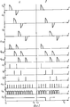
На фиг. 1 изображена функциональная схема устройства для защитного отключения тиристорного преобразователя при обрыве силовой цепи; на фиг. 2 а - осциллограммы напряжений устройства при нормальном режиме работы, б - осциллограммы напряжений устройства в аварийном режиме работы. In FIG. 1 shows a functional diagram of a device for protective shutdown of a thyristor converter in the event of an open circuit; in FIG. 2 a - waveforms of the voltage of the device during normal operation, b - waveforms of the voltage of the device in emergency operation.
Устройство (фиг. 1) для защитного отключения тиристорного преобразователя при обрыве силовой цепи содержит тиристорные коммутаторы 1, 2 и 3 со встречно-параллельно включенными тиристорами в каждой фазе, датчики тока 4, 5 и 6, формирователи коротких импульсов 7, 8 и 9, состоящие из выпрямителей 10, логических элементов И 11, дифференцирующих RC-цепей, ограничивающих диодов, блок суммирования 12, исполнительный орган 13, состоящий из логического элемента И-НЕ 14, расширителя импульсов 15 [3], исполнительного элемента защиты (триггера) 16, систему управления преобразователем 17. При этом датчики тока включены в каждой фазе двигателя, выходы датчиков тока 4, 5 и 6 подсоединены соответственно к входам формирователей коротких импульсов 7, 8 и 9. The device (Fig. 1) for the protective shutdown of the thyristor converter when the power circuit is broken contains thyristor switches 1, 2 and 3 with thyristors in opposite phase connected in each phase, current sensors 4, 5 and 6, short pulse shapers 7, 8 and 9, consisting of
Формирователь импульсов представляет собой последовательно соединенные выпрямители 10, логический элемент И 11, дифференциальную RC-цепь, ограничивающий диод, анод которого подсоединен к общей шине. Выходы формирователя каждой фазы подсоединены к входам блока суммирования 12, выход которого подключен на вход исполнительного органа 13, который состоит из последовательно соединенных логического элемента И-НЕ 14, расширителя импульсов 15, исполнительного элементах защиты 16. Выходной сигнал исполнительного органа 13 воздействует на блокировочный вход системы управления преобразователем. The pulse shaper is a series-connected
Устройство работает следующим образом. The device operates as follows.
Ток каждой фазы асинхронного электродвигателя 18 измеряется датчиками тока 4 - 6. Выходное напряжение датчиков тока подается на входы формирователей импульсов 7 - 9, которые формируют короткие импульсы по фронту импульсов тока в фазах питающего напряжения. Затем короткие импульсы с каждой фазы подаются на входы блока суммирования 12, выходной сигнал которого в виде последовательности импульсов с интервалом 60 эл. град. подается на вход исполнительного органа 13, а сигнал с его выхода - на блокировочный вход системы управления 17. The current of each phase of the induction motor 18 is measured by current sensors 4 to 6. The output voltage of the current sensors is fed to the inputs of the pulse shapers 7 to 9, which form short pulses along the front of the current pulses in the phases of the supply voltage. Then short pulses from each phase are fed to the inputs of the summing unit 12, the output signal of which is in the form of a sequence of pulses with an interval of 60 el. hail. fed to the input of the executive body 13, and the signal from its output to the blocking input of the control system 17.
В нормальном режиме работы (интервал времени 1-2) на фиг. 2,а в выходном напряжении каждой фазы преобразователя присутствуют симметричные отрезки синусоиды положительной и отрицательной полуволны. Напряжение каждой фазы выпрямляется выпрямителями 10 - напряжения U7-10 - U9-10 и в каждой фазе по передним фронтам напряжения U7-10 - U9-10 с помощью логических элементов 11, RC-цепей и диодов формируются короткие импульсы U7 - U9, отстоящие друг от друга на 180 эл. град., которые подаются на входы блока суммирования 12, на выходе которого образуется последовательность положительных единичных импульсов с интервалом 60 эл. град., которые подаются на вход исполнительного органа 13, где из положительных импульсы преобразуются в импульсы нулевого уровня логическим элементом И-НЕ 14 и с его выхода импульсы нулевого уровня подаются на вход расширителя импульсов 15. На выходе расширителя импульсов образуется напряжение единичного логического уровня, которое воздействует на исполнительный элемент 16 таким образом, что блокировочный сигнал на входе системы управления 17 преобразователя отсутствует и преобразователь находится в рабочем состоянии.In normal operation (time interval 1-2) in FIG. 2, and in the output voltage of each phase of the converter there are symmetrical segments of the sinusoid of the positive and negative half-waves. The voltage of each phase is rectified by rectifiers 10 - voltage U 7-10 - U 9-10 and in each phase along the leading edges of the voltage U 7-10 - U 9-10 , short pulses U 7 are formed using logic elements 11, RC circuits and diodes - U 9 , spaced from each other by 180 el. grad., which are fed to the inputs of the summing unit 12, the output of which forms a sequence of positive unit pulses with an interval of 60 el. grad., which are fed to the input of the executive body 13, where from positive pulses are converted into zero-level pulses by the AND-NOT 14 logic element and from its output, zero-level pulses are fed to the input of the pulse expander 15. At the output of the pulse expander, a voltage of a single logical level is generated, which acts on the actuating element 16 so that the blocking signal at the input of the control system 17 of the converter is absent and the converter is in working condition.
При исчезновении одного или нескольких импульсов напряжения в фазах тиристорного преобразователя, что соответствует обрыву фазы или невключению тиристора (фиг. 2,б, интервал t3 - t4), также сформируются на выходе 14 импульсы нулевого уровня, но с интервалом более чем 60 эл. град. Это вызовет появление нулевого уровня в выходном напряжении U15 расширителя импульсов 15. Нулевой сигнал с выхода 15, воздействуя на исполнительный элемент 16, блокирует управляющие импульсы тиристорного преобразователя, прекращая его работу.If one or more voltage pulses disappears in the phases of the thyristor converter, which corresponds to a phase failure or non-inclusion of the thyristor (Fig. 2b, interval t 3 - t 4 ), zero level pulses will also be generated at output 14, but with an interval of more than 60 e . hail. This will cause the appearance of a zero level in the output voltage U 15 of the pulse expander 15. The zero signal from output 15, acting on the actuating element 16, blocks the control pulses of the thyristor converter, stopping its operation.
Список литературы
1. Авторское свидетельство ССР N 1510045, кл. H 02 H 7/10, 1987. Устройство для защитного отключения тиристорного преобразователя при обрыве его вентильной цепи.Bibliography
1. Copyright certificate of the SSR N 1510045, cl. H 02 H 7/10, 1987. Device for protective shutdown of a thyristor converter when its valve circuit is broken.
2. Авторское свидетельство ССР N 1379863, кл. H 02 H 7/08, 1985. Устройство защиты от несимметричных режимов трехфазного асинхронного электродвигателя. 2. Copyright certificate of the Soviet Socialist Republic N 1379863, cl. H 02 H 7/08, 1985. Protection device against asymmetrical modes of a three-phase asynchronous electric motor.
3. Лысенко В. В. Функциональные элементы релейных устройств на интегральных микросхемах. М.: Энергоатомиздат, 1990, с. 115 - 117. 3. Lysenko VV Functional elements of relay devices on integrated circuits. M .: Energoatomizdat, 1990, p. 115 - 117.
Claims (2)
Priority Applications (1)
| Application Number | Priority Date | Filing Date | Title |
|---|---|---|---|
| RU92004202A RU2117373C1 (en) | 1992-10-27 | 1992-10-27 | Device for emergency disconnection of thyristor converter in response to open circuit in its power circuit |
Applications Claiming Priority (1)
| Application Number | Priority Date | Filing Date | Title |
|---|---|---|---|
| RU92004202A RU2117373C1 (en) | 1992-10-27 | 1992-10-27 | Device for emergency disconnection of thyristor converter in response to open circuit in its power circuit |
Publications (2)
| Publication Number | Publication Date |
|---|---|
| RU92004202A RU92004202A (en) | 1995-02-20 |
| RU2117373C1 true RU2117373C1 (en) | 1998-08-10 |
Family
ID=20131568
Family Applications (1)
| Application Number | Title | Priority Date | Filing Date |
|---|---|---|---|
| RU92004202A RU2117373C1 (en) | 1992-10-27 | 1992-10-27 | Device for emergency disconnection of thyristor converter in response to open circuit in its power circuit |
Country Status (1)
| Country | Link |
|---|---|
| RU (1) | RU2117373C1 (en) |
Cited By (4)
| Publication number | Priority date | Publication date | Assignee | Title |
|---|---|---|---|---|
| RU2161356C1 (en) * | 1999-10-25 | 2000-12-27 | Открытое акционерное общество Проектно-конструкторское бюро вагоностроения "Магистраль" | Protective device for pieces of high-voltage electrical equipment |
| RU2321125C1 (en) * | 2007-02-01 | 2008-03-27 | Анатолий Анатольевич Дьяконов | Off-operation protective device for electric instruments and apparatuses |
| RU2326480C1 (en) * | 2007-04-04 | 2008-06-10 | Государственное образовательное учреждение высшего профессионального образования Томский политехнический университет | Method of control and provision of survivability of three phase induction motor |
| RU2546062C2 (en) * | 2013-04-16 | 2015-04-10 | Анатолий Андреевич Лебедин | Reversible valve inverter |
-
1992
- 1992-10-27 RU RU92004202A patent/RU2117373C1/en active
Cited By (4)
| Publication number | Priority date | Publication date | Assignee | Title |
|---|---|---|---|---|
| RU2161356C1 (en) * | 1999-10-25 | 2000-12-27 | Открытое акционерное общество Проектно-конструкторское бюро вагоностроения "Магистраль" | Protective device for pieces of high-voltage electrical equipment |
| RU2321125C1 (en) * | 2007-02-01 | 2008-03-27 | Анатолий Анатольевич Дьяконов | Off-operation protective device for electric instruments and apparatuses |
| RU2326480C1 (en) * | 2007-04-04 | 2008-06-10 | Государственное образовательное учреждение высшего профессионального образования Томский политехнический университет | Method of control and provision of survivability of three phase induction motor |
| RU2546062C2 (en) * | 2013-04-16 | 2015-04-10 | Анатолий Андреевич Лебедин | Reversible valve inverter |
Similar Documents
| Publication | Publication Date | Title |
|---|---|---|
| US4675799A (en) | Control system for power converter | |
| KR970060623A (en) | Method and circuit to protect power circuit from short circuit and over current fault | |
| RU2117373C1 (en) | Device for emergency disconnection of thyristor converter in response to open circuit in its power circuit | |
| US3536957A (en) | Polyphase circuit input fault detection system | |
| RU2152679C1 (en) | Thyristor converter protective device | |
| US4263646A (en) | Missed commutation detector and safeguard arrangement | |
| JP3449172B2 (en) | Three-phase four-wire neutral-phase open-phase detector and circuit breaker | |
| US3343038A (en) | Phase loss detector and circuit controlled thereby | |
| JP4514278B2 (en) | Semiconductor control device | |
| JP2926933B2 (en) | Output short-circuit protection method for voltage type inverter | |
| SU1534620A1 (en) | Method of protection of thyristor inverter | |
| SU1149341A1 (en) | Protective de-energization device | |
| SU851599A1 (en) | Device for protecting from current leakage in shaft traction network with controllable thyristorized rectifier | |
| SU439047A1 (en) | Device for protection of electric power systems of direct current | |
| JPH0611489Y2 (en) | Fault detection circuit | |
| SU1525846A1 (en) | Device for controlling two fast-acting gates connected to common load | |
| SU997165A1 (en) | Device for protecting load from wrong phase alternation and phase break | |
| SU930476A1 (en) | Protective cut-out device for shaft traction dc networks | |
| SU736314A1 (en) | Electric drive of heavy longitudinally-working machine tool table | |
| SU978266A1 (en) | Device for protecting converter from short circuiting currents in outer circuits | |
| SU600646A1 (en) | Arrangement for protective disconnecting at earthing of contact dc network, including controlled power rectifier and triggering pulse interrupter in control circuit | |
| SU1367117A1 (en) | Thyristor inverter | |
| SU1081724A1 (en) | Device for current protection of a.c.power network against short circuit | |
| SU1356113A2 (en) | Apparatus for heat protection of electric motor | |
| SU976824A1 (en) | Device for protecting thyristor electric drive |