RU2114792C1 - Plant for biochemically removing organic and nitrogen containing impurities from concentrated waste waters - Google Patents
Plant for biochemically removing organic and nitrogen containing impurities from concentrated waste waters Download PDFInfo
- Publication number
- RU2114792C1 RU2114792C1 RU95119517A RU95119517A RU2114792C1 RU 2114792 C1 RU2114792 C1 RU 2114792C1 RU 95119517 A RU95119517 A RU 95119517A RU 95119517 A RU95119517 A RU 95119517A RU 2114792 C1 RU2114792 C1 RU 2114792C1
- Authority
- RU
- Russia
- Prior art keywords
- pipe
- water
- receiving chamber
- iii
- circulation
- Prior art date
Links
Images


Classifications
-
- Y—GENERAL TAGGING OF NEW TECHNOLOGICAL DEVELOPMENTS; GENERAL TAGGING OF CROSS-SECTIONAL TECHNOLOGIES SPANNING OVER SEVERAL SECTIONS OF THE IPC; TECHNICAL SUBJECTS COVERED BY FORMER USPC CROSS-REFERENCE ART COLLECTIONS [XRACs] AND DIGESTS
- Y02—TECHNOLOGIES OR APPLICATIONS FOR MITIGATION OR ADAPTATION AGAINST CLIMATE CHANGE
- Y02W—CLIMATE CHANGE MITIGATION TECHNOLOGIES RELATED TO WASTEWATER TREATMENT OR WASTE MANAGEMENT
- Y02W10/00—Technologies for wastewater treatment
- Y02W10/10—Biological treatment of water, waste water, or sewage
Landscapes
- Biological Treatment Of Waste Water (AREA)
Abstract
Description
Изобретение относится к биохимической очистке концентрированных сточных вод с содержанием органических загрязнений по БПК от 1000 до 3000 мг/л, азота аммонийных солей до 150 мг/л и может быть использовано при очистке производственных сточных вод мясокомбинатов, звероводческих ферм, птицефабрик, маслосырзаводов и т.д., а также в микробиологическом и химическом синтезе. The invention relates to biochemical treatment of concentrated wastewater with an organic impurity content of BOD from 1000 to 3000 mg / l, ammonium nitrogen up to 150 mg / l and can be used in the treatment of industrial wastewater from meat plants, fur farms, poultry farms, creameries, etc. D., as well as in microbiological and chemical synthesis.
Наиболее близкой по достигаемому эффекту является установка для биохимической очистки концентрированных вод от органических и азотсодержащих загрязнений, содержащая комбинированное устройство, включающее биофильтр с системой орошения, цилиндроконический аэротенк-отстойник с водоструйными аэрационными колоннами и трубопроводом отвода иловой смеси, камеру смешения, циркуляционный насос и технологические трубопроводы [1]. The closest effect to be achieved is a plant for the biochemical treatment of concentrated water from organic and nitrogen-containing contaminants, containing a combined device including a biofilter with an irrigation system, a cylinder-conical aeration tank with water-jet aeration columns and a sludge discharge pipe, a mixing chamber, a circulation pump and process pipelines [one].
Для очистки сточных вод более эффективна многостадийная схема, обеспечивающая на каждой стадии адаптацию определенных видов микроорганизмов и различные режимы процесса биохимического окисления. For wastewater treatment, a multi-stage scheme is more effective, which ensures at each stage the adaptation of certain types of microorganisms and various modes of the biochemical oxidation process.
При большой производительности значительно увеличивается строительная высота аэротенков-отстойников, а при устройстве днища из нескольких конических приямков с отведением ила из каждого усложняется регулировка гидродинамического режима циркуляции иловой смеси. With high productivity, the construction height of the aeration tanks-sumps increases significantly, and when the bottom is made up of several conical pits with drainage of sludge from each, it becomes more difficult to adjust the hydrodynamic circulation mode of the sludge mixture.
Задачами предлагаемой установки являются расширение диапазона применения, повышение степени очистки концентрированных сточных вод, сокращение строительной высоты сооружений и эксплуатационных затрат. The objectives of the proposed installation are to expand the range of applications, increase the degree of purification of concentrated wastewater, reduce the construction height of structures and operating costs.
Поставленные задачи решаются тем, что в технологическую схему установки включен биокоагулятор I, оборудованный перфорированным трубопроводом с регулятором расхода жидкости на отводном трубопроводе к комбинированному устройству II, циркуляционный трубопровод которого подсоединен к приемной камере аэратора 1 и к дополнительно включенному в схему реактору для подготовки субстрата IV. В качестве второй ступени очистки и нитрификатора имеется также комбинированное устройство III, оборудованное затопленной загрузкой и гелий-неоновыми лазерами (ГНЛ) и снабженное дополнительным трубопроводом, который подсоединен к циркуляционному трубопроводу III и к приемной камере 1, а отводной трубопровод подсоединен к распределительному лотку аэробного биореактора-нитрификатора V, оборудованного коаксиально расположенной камерой насыщения жидкости кислородом, искусственной загрузкой, отстойной зоной, циркуляционным насосом, который подсоединен к перфорированному трубопроводу и к приемной камере водоструйного аэратора, а также отводящим трубопроводом, подключенным к смесителю, к которому в свою очередь подсоединен трубопроводом IV. Смеситель соединен с распределительной системой денитрификатора IV, оборудованного искусственной загрузкой и водоструйным аэратором. The tasks are solved by the fact that the biocoagulator I is equipped with a perforated pipeline with a fluid flow regulator on the branch pipe to the combined device II, the circulation pipe of which is connected to the receiving chamber of the aerator 1 and to the reactor additionally included in the scheme for preparing substrate IV. As the second stage of purification and nitrification, there is also a combined device III, equipped with a flooded loading and helium-neon lasers (GNL) and equipped with an additional pipe, which is connected to the circulation pipe III and to the receiving chamber 1, and the drain pipe is connected to the distribution tray of the aerobic bioreactor -nitrifier V, equipped with a coaxially located oxygen saturation chamber, artificial loading, settling zone, circulation pump, which d is connected to a perforated conduit and the receiving chamber to the water jet aerator, and the discharging pipe connected to the mixer, which in turn is coupled IV tubing. The mixer is connected to the IV denitrification distribution system equipped with artificial loading and a water-jet aerator.
Днище II и III выполнено плоским с устройством валиков с углами наклона откосов 45-65o, разделяющими днище на ячейки. При этом нижние торцы аэрационных колонн располагаются на расстоянии 0,2-0,7 м от днища и расставлены равномерно по проекции к плоскости днищ ячеек, а трубопровод отвода иловой смеси всасывающими патрубками расположен по периметру днища аэротенка-отстойника и на расстоянии 0,1-0,5 м от днища. Загрузка выполнена из искусственного материала, представляющего пластины с отверстиями и щетинками.The bottom II and III is made flat with the device rollers with slope angles of slopes of 45-65 o dividing the bottom into cells. At the same time, the lower ends of the aeration columns are located at a distance of 0.2-0.7 m from the bottom and are evenly spaced along the projection to the plane of the cell bottoms, and the sludge discharge pipe with suction pipes is located around the perimeter of the bottom of the aeration tank-settler and at a distance of 0.1- 0.5 m from the bottom. The loading is made of artificial material representing plates with holes and bristles.
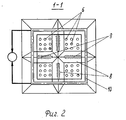
На фиг. 1 изображена технологическая схема установки для биохимической очистки концентрированных сточных вод от органических и азотсодержащих загрязнений; на фиг. 2 и 3 - план и разрез нижней части устройства II и III, соответственно; на фиг. 4-6 - виды и разрез искусственной загрузки, соответственно. In FIG. 1 shows a process diagram of a plant for biochemical treatment of concentrated wastewater from organic and nitrogen-containing contaminants; in FIG. 2 and 3 - plan and section of the lower part of the device II and III, respectively; in FIG. 4-6 - types and section of artificial loading, respectively.
Установка включает трубопровод подачи исходной сточной жидкости 1, подсоединенный к приемной камере водоструйного аэратора 2 биокоагулятора - усреднителя 1, который подсоединен трубопроводом с регулятором расхода жидкости 3 к камере смешения 4 комбинированного устройства II, состоящего из биофильтра 5 с системой орошения и сборным поддоном, к которому подсоединены аэрационные колонны 6, основная часть которых заглублена в аэротенке на один уровень. Расстояние от нижних торцов колонн до днища аэротенка-отстойника 7 составляет 0,2-0,7 м. Днище выполняется горизонтальным с устройством откосов и валиков 8 с углами наклона 45-65o. Над валиками 8 устанавливается фиксированная загрузка в виде пластин 9, имеющих отверстия и щетинки. Сборный трубопровод 10 с всасывающими патрубками располагается по периметру днища и с расстояниями от днища 0,1-0,5 м. Циркуляционный трубопровод устройства II подсоединен трубопроводом 11 к приемной камере 2 биокоагулятора-усреднителя 1 и трубопроводом 12 к реактору для подготовки органического субстрата IV.The installation includes a feed pipe for the initial waste fluid 1, connected to the receiving chamber of the water-
Устройство II в свою очередь соединено трубопроводом с камерой смешения комбинированного устройства III, циркуляционный трубопровод которого подсоединен также трубопроводом 13 к приемной камере 2 биокоагулятора-усреднителя I. The device II, in turn, is connected by a pipe to the mixing chamber of the combined device III, the circulation pipe of which is also connected by a pipe 13 to the
Комбинированное устройство III подсоединено трубопроводом к распределительному лотку 14 аэробного биореактора V, оборудованного приемной камерой 15 с аэрационными колоннами 16, размещенными в коаксиально расположенной камере аэрации 17, фиксированной загрузкой 18 из штампованных пластмассовых листов с отверстиями и щетинками, подвешенных вертикально, выделенной по периметру резервуара отстойной зоной 19 со сборным лотком, циркуляционным насосом 20, всасывающий трубопровод которого подсоединен к перфорированному трубопроводу 21, уложенному по внутреннему периметру реактора V, а напорный трубопровод 22 подсоединен к приемной камере 15. The combined device III is connected by a pipeline to the distribution tray 14 of the aerobic bioreactor V, equipped with a receiving chamber 15 with aeration columns 16 located in a coaxially located aeration chamber 17, a fixed load of 18 from stamped plastic sheets with holes and bristles suspended vertically, allocated around the tank perimeter zone 19 with a collection tray, a circulation pump 20, the suction pipe of which is connected to a perforated pipe 21, laid along the inner perimeter of the reactor V, and the pressure pipe 22 is connected to the receiving chamber 15.
Сборный лоток реактора V подсоединен трубопроводом 23 к смесителю 24, куда также подсоединен трубопроводом 25 реактор IV. В свою очередь смеситель 24 подсоединен трубопроводом 26 к распределительной системе 27 денитрификатора IV. В емкости денитрификатора установлена загрузка 28 также из пластмассовых штампованных листов с отверстиями и щетинками и сборные лотки, подсоединенные трубопроводом к водоструйному аэратору 29. The collecting tray of the reactor V is connected by a pipe 23 to the mixer 24, where reactor IV is also connected by a pipe 25. In turn, the mixer 24 is connected by a pipe 26 to the distribution system 27 of the denitrifier IV. In the container of the denitrifier, a load of 28 is also made of stamped plastic sheets with holes and bristles and prefabricated trays connected by a pipeline to the water-jet aerator 29.
На фиг. 2, 3 изображен план и разрез нижней части днища комбинированных устройств II, III с валиками 8, откосами и координатной сеткой размещения аэрационных колонн 6 и отводящим трубопроводом 10 с всасывающими патрубками 30. На фиг. 4 - 6 изображены виды и разрез искусственной загрузки с отверстиями и щетинками. In FIG. 2, 3 show a plan and a section of the lower part of the bottom of the combined devices II, III with
Установка для биохимической очистки концентрированных сточных вод от органических и азотсодержащих загрязнений работает следующим образом. Installation for biochemical treatment of concentrated wastewater from organic and nitrogen-containing pollution works as follows.
Сточные воды после предварительной механической обработки подаются в приемную камеру 2 водоструйного аэратора биокоагулятора-усреднителя I. Туда же по трубопроводу 13 подается иловая смесь (избыточная биомасса) из комбинированного устройства III и по трубопроводу 11 часть иловой смеси (избыточная биомасса) из комбинированного устройства II. Биокоагулятор-усреднитель предназначен для снижения концентрации взвешенных веществ на 50-60% и органических загрязнений по БПК 20-25%. При этом содержание снизится на 7-10%. After preliminary mechanical treatment, the wastewater is fed into the
Осветленная сточная жидкость, собранная перфорированным трубопроводом через трубопровод с регулятором расхода 3, равномерно отводится в камеру смешения 4 устройства II. The clarified wastewater collected by the perforated pipe through a pipe with a flow regulator 3 is evenly discharged into the mixing chamber 4 of the device II.
Комбинированное устройство II предназначено для окисления органических загрязнений сточных вод при высоких нагрузках на ил. Образование биоценоза на щетинках загрузки 9 повышает концентрацию активной биомассы в реакционном объеме аэротенка. Наличие отверстий способствует смешению потоков. Combined device II is designed for the oxidation of organic wastewater contaminants at high loads on sludge. The formation of biocenosis on the bristles of the
Эффективность очистки исходных стоков на данной стадии составит по БПК 45-60%, по взвешенным веществам 35-40%. The efficiency of purification of the initial effluents at this stage will be 45-60% for BOD and 35-40% for suspended solids.
При исходной концентрации N-NH
Предложенная схема расстановки аэрационных колонн 6 и конструкция днища с валиками 8 обеспечивают эффективное перемешивание иловой смеси в зоне аэрации и исключает образование зон залегания ила. Наличие всасывающих патрубков 30 на трубопроводе 10 обеспечивает равномерное отведение иловой смеси по всему периметру днища. Осветленная, частично очищенная жидкость после комбинированного устройства II поступает в камеру смешения устройства III, в котором осуществляется очистка сточной жидкости при низких нагрузках на биомассу. Для интенсификации биохимических процессов производится облучение циркулирующей жидкости с помощью гелий-неоновых лазеров (ГНЛ). Эффективность очистки сточных вод на данной стадии составит от БПК исходной сточной жидкости 25-35%. Снижение N-NH
Осветленная, очищенная жидкость из устройства III направляется в распределительный лоток 13 аэробного реактора V. Обеспечение биохимического процесса кислородом, перемешивание содержимого и движение жидкости через загрузку 18 осуществляются с помощью циркуляционного насоса 20, забирающего жидкость через перфорированный трубопровод 21 и подающего циркулирующую жидкость по трубопроводу 22 в приемную камеру 15 водоструйного аэратора с аэрационными колоннами 16. The clarified, purified liquid from the device III is sent to the distribution tray 13 of the aerobic reactor V. The oxygen supply of the biochemical process, the mixing of the contents and the movement of the liquid through the charge 18 are carried out using a circulation pump 20 that draws the liquid through the perforated pipe 21 and feeds the circulating liquid through the pipe 22 c the receiving chamber 15 of the water-jet aerator with aeration columns 16.
В камере аэрации 17 происходит насыщение жидкости кислородом воздуха. Жидкость, содержащая растворенный кислород, поступает в пространство над загрузкой 18, где смешивается с жидкостью, поступающей через лоток 14 из устройства III. In the aeration chamber 17, the liquid is saturated with oxygen. The liquid containing dissolved oxygen enters the space above the charge 18, where it is mixed with the liquid entering through the tray 14 from the device III.
При циркуляции жидкости через загрузку в направлении "сверху вниз" происходит окисление иммобилизованной на загрузке микрофлорой остаточных органических загрязнений. When the liquid circulates through the load in the direction from top to bottom, oxidation of residual organic pollutants immobilized at the load by microflora occurs.
Реактор V предназначен для доведения степени очистки очищенных сточных вод по БПК и взвешенным веществам до 3 мг/л, осуществления процесса отдувки оставшегося аммонийного азота и завершения нитрификации. Reactor V is designed to bring the degree of purification of treated wastewater by BOD and suspended solids to 3 mg / l, the process of blowing the remaining ammonium nitrogen and complete nitrification.
На данном этапе содержание N-NH
При облучении иловой смеси гелий-неоновыми лазерами скорость роста микроорганизмов возрастает в 2-3 раза и соответственно сокращается время, необходимое для полной сорбции оставшихся загрязнений. Это позволяет исключить вторичное загрязнение очищенной жидкости при осуществлении процессов денитрификации. When the silt mixture is irradiated with helium-neon lasers, the growth rate of microorganisms increases by 2–3 times and, accordingly, the time required for complete sorption of the remaining contaminants is reduced. This eliminates the secondary contamination of the purified liquid during denitrification processes.
Из смесителя 24 смесь очищенной воды и субстрата по трубопроводу 26 подается в распределительную систему 27 денитрификатора IV. Далее жидкость проходит через слой взвешенного и иммобилизованного на загрузке 28 денитрифицирующего ила, где задерживаются частицы хлопьевидного субстрата и затем используются для питания факультативных анаэробов. В денитрификаторе эффективность удаления нитратного азота составит 90-95%. Остаточные концентрации различных форм минерального азота после отдувки составят: N-NH
Использование изобретения позволяет получить высокий эффект очистки сточных вод с высоким содержанием трудноокисляемых органических веществ и азота аммонийных солей. The use of the invention allows to obtain a high effect of wastewater treatment with a high content of hardly oxidizable organic substances and nitrogen of ammonium salts.
Claims (3)
Priority Applications (3)
| Application Number | Priority Date | Filing Date | Title |
|---|---|---|---|
| RU95119517A RU2114792C1 (en) | 1995-11-15 | 1995-11-15 | Plant for biochemically removing organic and nitrogen containing impurities from concentrated waste waters |
| PCT/RU1996/000202 WO1997005070A1 (en) | 1995-07-26 | 1996-07-25 | Facility for the biochemical purification of effluent |
| AU73468/96A AU7346896A (en) | 1995-07-26 | 1996-07-25 | Facility for the biochemical purification of effluent |
Applications Claiming Priority (1)
| Application Number | Priority Date | Filing Date | Title |
|---|---|---|---|
| RU95119517A RU2114792C1 (en) | 1995-11-15 | 1995-11-15 | Plant for biochemically removing organic and nitrogen containing impurities from concentrated waste waters |
Publications (1)
| Publication Number | Publication Date |
|---|---|
| RU2114792C1 true RU2114792C1 (en) | 1998-07-10 |
Family
ID=20173908
Family Applications (1)
| Application Number | Title | Priority Date | Filing Date |
|---|---|---|---|
| RU95119517A RU2114792C1 (en) | 1995-07-26 | 1995-11-15 | Plant for biochemically removing organic and nitrogen containing impurities from concentrated waste waters |
Country Status (1)
| Country | Link |
|---|---|
| RU (1) | RU2114792C1 (en) |
Cited By (9)
| Publication number | Priority date | Publication date | Assignee | Title |
|---|---|---|---|---|
| RU2162824C1 (en) * | 1999-11-17 | 2001-02-10 | Закрытое акционерное общество "Куйбышевазот" | System for biochemical purification of sewage waters from organic and nitrogen-containing compounds and water return for water supply of enterprise |
| RU2185332C1 (en) * | 2001-06-01 | 2002-07-20 | Ракитин Георгий Валентинович | Device for purification of aqueous solutions |
| RU2220915C2 (en) * | 2001-01-17 | 2004-01-10 | Колесникова Надежда Владимировна | Installation for biochemical purification of sewage |
| RU2390502C2 (en) * | 2004-06-02 | 2010-05-27 | ОуТиВи ЭсЭй | Method of treating water using biological reactor and device for realising said method |
| MD4015C2 (en) * | 2009-02-20 | 2010-09-30 | Государственный Университет Молд0 | Process for the purification of sewage waters from ammonium nitrogen |
| RU2440932C2 (en) * | 2010-04-06 | 2012-01-27 | Владимир Петрович Колесников | Installation for deep biochemical treatment of effluents with high content of organic contaminants, carbon sulphide, hydrosulphides, and ammonium nitrogen |
| WO2012033423A1 (en) * | 2010-09-09 | 2012-03-15 | Kolesnikov Vladimir Petrovich | Apparatus for thorough biochemical purification of waste water |
| US8685235B2 (en) | 2009-02-04 | 2014-04-01 | Vladimir Petrovich Kolesnjkov | Integrated sewage treatment plant |
| RU2711619C1 (en) * | 2019-07-30 | 2020-01-17 | Федеральное государственное бюджетное образовательное учреждение высшего образования "Тульский государственный университет" (ТулГУ) | Automated device for domestic waste water treatment |
-
1995
- 1995-11-15 RU RU95119517A patent/RU2114792C1/en not_active IP Right Cessation
Non-Patent Citations (1)
| Title |
|---|
| SU, авторское свидетельство N 1761688, кл. 6 C 02 F 3/02, 1992. * |
Cited By (10)
| Publication number | Priority date | Publication date | Assignee | Title |
|---|---|---|---|---|
| RU2162824C1 (en) * | 1999-11-17 | 2001-02-10 | Закрытое акционерное общество "Куйбышевазот" | System for biochemical purification of sewage waters from organic and nitrogen-containing compounds and water return for water supply of enterprise |
| RU2220915C2 (en) * | 2001-01-17 | 2004-01-10 | Колесникова Надежда Владимировна | Installation for biochemical purification of sewage |
| RU2185332C1 (en) * | 2001-06-01 | 2002-07-20 | Ракитин Георгий Валентинович | Device for purification of aqueous solutions |
| RU2390502C2 (en) * | 2004-06-02 | 2010-05-27 | ОуТиВи ЭсЭй | Method of treating water using biological reactor and device for realising said method |
| US8685235B2 (en) | 2009-02-04 | 2014-04-01 | Vladimir Petrovich Kolesnjkov | Integrated sewage treatment plant |
| MD4015C2 (en) * | 2009-02-20 | 2010-09-30 | Государственный Университет Молд0 | Process for the purification of sewage waters from ammonium nitrogen |
| RU2440932C2 (en) * | 2010-04-06 | 2012-01-27 | Владимир Петрович Колесников | Installation for deep biochemical treatment of effluents with high content of organic contaminants, carbon sulphide, hydrosulphides, and ammonium nitrogen |
| EA023425B1 (en) * | 2010-04-06 | 2016-06-30 | Владимир Петрович КОЛЕСНИКОВ | Apparatus for deep biochemical wastewater treatment |
| WO2012033423A1 (en) * | 2010-09-09 | 2012-03-15 | Kolesnikov Vladimir Petrovich | Apparatus for thorough biochemical purification of waste water |
| RU2711619C1 (en) * | 2019-07-30 | 2020-01-17 | Федеральное государственное бюджетное образовательное учреждение высшего образования "Тульский государственный университет" (ТулГУ) | Automated device for domestic waste water treatment |
Similar Documents
| Publication | Publication Date | Title |
|---|---|---|
| US5514277A (en) | Treatment of wastewater and sludges | |
| AU2004274400B2 (en) | Single vessel multi-zone wastewater bio-treatment system | |
| CA2132592C (en) | A method of treating wastewater | |
| CN102173510A (en) | Sludge reflow-free device with simultaneous nitrification and denitrification (SND) function and operation control method thereof | |
| CN108383320A (en) | A kind of integrated processing method of livestock breeding wastewater | |
| CN114988632A (en) | Domestic sewage sludge synchronous ecological treatment integrated equipment and treatment method | |
| CN112551828A (en) | Low-carbon-nitrogen-ratio rural domestic sewage treatment device and treatment process thereof | |
| RU2114792C1 (en) | Plant for biochemically removing organic and nitrogen containing impurities from concentrated waste waters | |
| CN210001741U (en) | Sewage treatment device | |
| RU189953U1 (en) | INSTALLATION FOR BIOLOGICAL PURIFICATION OF COMMUNAL WASTEWATER FROM NITROGEN AND Phosphorus compounds | |
| CN210825829U (en) | Improvement type MBR sewage treatment device | |
| KR20140132258A (en) | Biological Advanced Wastewater Treatment Technology | |
| US20220073390A1 (en) | Fixed Biofilm Anaerobic-Aerobic Combined Reactor For Treating Wastewater | |
| CN216377647U (en) | High-efficient pulse water distribution anaerobism sludge denitrification reaction unit | |
| RU2114070C1 (en) | Installation for biochemically removing organic and nitrogen containing impurities from waste waters | |
| CA1155976A (en) | Apparatus for anoxic-aerobic activated sludge process and treatment of waste waters | |
| RU2136614C1 (en) | Device for biological elimination of organic substances, nitrogen and phosphorus compounds from sewage waters | |
| CN211644993U (en) | Urban domestic sewage integrated treatment device | |
| RU10167U1 (en) | BIOREACTOR FOR WASTE WATER TREATMENT FROM BIOGENIC ELEMENTS - NITROGEN AND PHOSPHORUS | |
| CN210393887U (en) | Small-size sewage treatment integration equipment | |
| CN218931842U (en) | Sludge reduction sewage treatment system | |
| CN220926516U (en) | Integrated automatic control air supply distributed MABR treatment equipment | |
| CN112979078A (en) | Continuous water inlet sewage treatment process and treatment device thereof | |
| CN219860898U (en) | Vertical integrated bioreactor | |
| JP2673488B2 (en) | Method and apparatus for treating organic wastewater |
Legal Events
| Date | Code | Title | Description |
|---|---|---|---|
| MM4A | The patent is invalid due to non-payment of fees |
Effective date: 20091116 |