RU2114690C1 - Method and device for circulation of substance in fluidized solids reactor - Google Patents
Method and device for circulation of substance in fluidized solids reactor Download PDFInfo
- Publication number
- RU2114690C1 RU2114690C1 RU95117992A RU95117992A RU2114690C1 RU 2114690 C1 RU2114690 C1 RU 2114690C1 RU 95117992 A RU95117992 A RU 95117992A RU 95117992 A RU95117992 A RU 95117992A RU 2114690 C1 RU2114690 C1 RU 2114690C1
- Authority
- RU
- Russia
- Prior art keywords
- chamber
- particles
- particle
- reactor
- end wall
- Prior art date
Links
Images
Classifications
-
- B—PERFORMING OPERATIONS; TRANSPORTING
- B01—PHYSICAL OR CHEMICAL PROCESSES OR APPARATUS IN GENERAL
- B01J—CHEMICAL OR PHYSICAL PROCESSES, e.g. CATALYSIS OR COLLOID CHEMISTRY; THEIR RELEVANT APPARATUS
- B01J8/00—Chemical or physical processes in general, conducted in the presence of fluids and solid particles; Apparatus for such processes
- B01J8/18—Chemical or physical processes in general, conducted in the presence of fluids and solid particles; Apparatus for such processes with fluidised particles
- B01J8/24—Chemical or physical processes in general, conducted in the presence of fluids and solid particles; Apparatus for such processes with fluidised particles according to "fluidised-bed" technique
- B01J8/26—Chemical or physical processes in general, conducted in the presence of fluids and solid particles; Apparatus for such processes with fluidised particles according to "fluidised-bed" technique with two or more fluidised beds, e.g. reactor and regeneration installations
-
- B—PERFORMING OPERATIONS; TRANSPORTING
- B01—PHYSICAL OR CHEMICAL PROCESSES OR APPARATUS IN GENERAL
- B01J—CHEMICAL OR PHYSICAL PROCESSES, e.g. CATALYSIS OR COLLOID CHEMISTRY; THEIR RELEVANT APPARATUS
- B01J8/00—Chemical or physical processes in general, conducted in the presence of fluids and solid particles; Apparatus for such processes
- B01J8/18—Chemical or physical processes in general, conducted in the presence of fluids and solid particles; Apparatus for such processes with fluidised particles
- B01J8/1836—Heating and cooling the reactor
-
- B—PERFORMING OPERATIONS; TRANSPORTING
- B01—PHYSICAL OR CHEMICAL PROCESSES OR APPARATUS IN GENERAL
- B01J—CHEMICAL OR PHYSICAL PROCESSES, e.g. CATALYSIS OR COLLOID CHEMISTRY; THEIR RELEVANT APPARATUS
- B01J8/00—Chemical or physical processes in general, conducted in the presence of fluids and solid particles; Apparatus for such processes
- B01J8/18—Chemical or physical processes in general, conducted in the presence of fluids and solid particles; Apparatus for such processes with fluidised particles
- B01J8/24—Chemical or physical processes in general, conducted in the presence of fluids and solid particles; Apparatus for such processes with fluidised particles according to "fluidised-bed" technique
- B01J8/38—Chemical or physical processes in general, conducted in the presence of fluids and solid particles; Apparatus for such processes with fluidised particles according to "fluidised-bed" technique with fluidised bed containing a rotatable device or being subject to rotation or to a circulatory movement, i.e. leaving a vessel and subsequently re-entering it
- B01J8/384—Chemical or physical processes in general, conducted in the presence of fluids and solid particles; Apparatus for such processes with fluidised particles according to "fluidised-bed" technique with fluidised bed containing a rotatable device or being subject to rotation or to a circulatory movement, i.e. leaving a vessel and subsequently re-entering it being subject to a circulatory movement only
- B01J8/388—Chemical or physical processes in general, conducted in the presence of fluids and solid particles; Apparatus for such processes with fluidised particles according to "fluidised-bed" technique with fluidised bed containing a rotatable device or being subject to rotation or to a circulatory movement, i.e. leaving a vessel and subsequently re-entering it being subject to a circulatory movement only externally, i.e. the particles leaving the vessel and subsequently re-entering it
-
- F—MECHANICAL ENGINEERING; LIGHTING; HEATING; WEAPONS; BLASTING
- F22—STEAM GENERATION
- F22B—METHODS OF STEAM GENERATION; STEAM BOILERS
- F22B31/00—Modifications of boiler construction, or of tube systems, dependent on installation of combustion apparatus; Arrangements of dispositions of combustion apparatus
- F22B31/0007—Modifications of boiler construction, or of tube systems, dependent on installation of combustion apparatus; Arrangements of dispositions of combustion apparatus with combustion in a fluidized bed
- F22B31/0084—Modifications of boiler construction, or of tube systems, dependent on installation of combustion apparatus; Arrangements of dispositions of combustion apparatus with combustion in a fluidized bed with recirculation of separated solids or with cooling of the bed particles outside the combustion bed
- F22B31/0092—Modifications of boiler construction, or of tube systems, dependent on installation of combustion apparatus; Arrangements of dispositions of combustion apparatus with combustion in a fluidized bed with recirculation of separated solids or with cooling of the bed particles outside the combustion bed with a fluidized heat exchange bed and a fluidized combustion bed separated by a partition, the bed particles circulating around or through that partition
-
- F—MECHANICAL ENGINEERING; LIGHTING; HEATING; WEAPONS; BLASTING
- F23—COMBUSTION APPARATUS; COMBUSTION PROCESSES
- F23C—METHODS OR APPARATUS FOR COMBUSTION USING FLUID FUEL OR SOLID FUEL SUSPENDED IN A CARRIER GAS OR AIR
- F23C10/00—Fluidised bed combustion apparatus
- F23C10/02—Fluidised bed combustion apparatus with means specially adapted for achieving or promoting a circulating movement of particles within the bed or for a recirculation of particles entrained from the bed
- F23C10/04—Fluidised bed combustion apparatus with means specially adapted for achieving or promoting a circulating movement of particles within the bed or for a recirculation of particles entrained from the bed the particles being circulated to a section, e.g. a heat-exchange section or a return duct, at least partially shielded from the combustion zone, before being reintroduced into the combustion zone
- F23C10/08—Fluidised bed combustion apparatus with means specially adapted for achieving or promoting a circulating movement of particles within the bed or for a recirculation of particles entrained from the bed the particles being circulated to a section, e.g. a heat-exchange section or a return duct, at least partially shielded from the combustion zone, before being reintroduced into the combustion zone characterised by the arrangement of separation apparatus, e.g. cyclones, for separating particles from the flue gases
- F23C10/10—Fluidised bed combustion apparatus with means specially adapted for achieving or promoting a circulating movement of particles within the bed or for a recirculation of particles entrained from the bed the particles being circulated to a section, e.g. a heat-exchange section or a return duct, at least partially shielded from the combustion zone, before being reintroduced into the combustion zone characterised by the arrangement of separation apparatus, e.g. cyclones, for separating particles from the flue gases the separation apparatus being located outside the combustion chamber
-
- B—PERFORMING OPERATIONS; TRANSPORTING
- B01—PHYSICAL OR CHEMICAL PROCESSES OR APPARATUS IN GENERAL
- B01J—CHEMICAL OR PHYSICAL PROCESSES, e.g. CATALYSIS OR COLLOID CHEMISTRY; THEIR RELEVANT APPARATUS
- B01J2208/00—Processes carried out in the presence of solid particles; Reactors therefor
- B01J2208/00008—Controlling the process
- B01J2208/00017—Controlling the temperature
- B01J2208/00026—Controlling or regulating the heat exchange system
- B01J2208/00035—Controlling or regulating the heat exchange system involving measured parameters
- B01J2208/00088—Flow rate measurement
-
- B—PERFORMING OPERATIONS; TRANSPORTING
- B01—PHYSICAL OR CHEMICAL PROCESSES OR APPARATUS IN GENERAL
- B01J—CHEMICAL OR PHYSICAL PROCESSES, e.g. CATALYSIS OR COLLOID CHEMISTRY; THEIR RELEVANT APPARATUS
- B01J2208/00—Processes carried out in the presence of solid particles; Reactors therefor
- B01J2208/00008—Controlling the process
- B01J2208/00017—Controlling the temperature
- B01J2208/00106—Controlling the temperature by indirect heat exchange
- B01J2208/00115—Controlling the temperature by indirect heat exchange with heat exchange elements inside the bed of solid particles
- B01J2208/00132—Tubes
-
- B—PERFORMING OPERATIONS; TRANSPORTING
- B01—PHYSICAL OR CHEMICAL PROCESSES OR APPARATUS IN GENERAL
- B01J—CHEMICAL OR PHYSICAL PROCESSES, e.g. CATALYSIS OR COLLOID CHEMISTRY; THEIR RELEVANT APPARATUS
- B01J2208/00—Processes carried out in the presence of solid particles; Reactors therefor
- B01J2208/00008—Controlling the process
- B01J2208/00017—Controlling the temperature
- B01J2208/00106—Controlling the temperature by indirect heat exchange
- B01J2208/00168—Controlling the temperature by indirect heat exchange with heat exchange elements outside the bed of solid particles
- B01J2208/00212—Plates; Jackets; Cylinders
-
- B—PERFORMING OPERATIONS; TRANSPORTING
- B01—PHYSICAL OR CHEMICAL PROCESSES OR APPARATUS IN GENERAL
- B01J—CHEMICAL OR PHYSICAL PROCESSES, e.g. CATALYSIS OR COLLOID CHEMISTRY; THEIR RELEVANT APPARATUS
- B01J2208/00—Processes carried out in the presence of solid particles; Reactors therefor
- B01J2208/00008—Controlling the process
- B01J2208/00017—Controlling the temperature
- B01J2208/00477—Controlling the temperature by thermal insulation means
- B01J2208/00495—Controlling the temperature by thermal insulation means using insulating materials or refractories
-
- F—MECHANICAL ENGINEERING; LIGHTING; HEATING; WEAPONS; BLASTING
- F23—COMBUSTION APPARATUS; COMBUSTION PROCESSES
- F23C—METHODS OR APPARATUS FOR COMBUSTION USING FLUID FUEL OR SOLID FUEL SUSPENDED IN A CARRIER GAS OR AIR
- F23C2206/00—Fluidised bed combustion
- F23C2206/10—Circulating fluidised bed
- F23C2206/101—Entrained or fast fluidised bed
-
- F—MECHANICAL ENGINEERING; LIGHTING; HEATING; WEAPONS; BLASTING
- F23—COMBUSTION APPARATUS; COMBUSTION PROCESSES
- F23C—METHODS OR APPARATUS FOR COMBUSTION USING FLUID FUEL OR SOLID FUEL SUSPENDED IN A CARRIER GAS OR AIR
- F23C2206/00—Fluidised bed combustion
- F23C2206/10—Circulating fluidised bed
- F23C2206/103—Cooling recirculating particles
Abstract
Description
Изобретение относится к способу и устройству для циркуляции твердых веществ в реакторе с псевдоожиженным слоем, включающем камеру реактора, имеющую боковые стенки, ограничивающие внутреннее пространство камеры реактора, и решетку на дне камеры реактора; отверстие для выпуска газа, примыкающее к верхней части камеры реактора и псевдоожиженный слой твердых частиц в камере реактора, причем псевдоожиженный слой имеет внутреннюю циркуляцию твердых частиц. The invention relates to a method and apparatus for circulating solids in a fluidized bed reactor, comprising a reactor chamber having side walls defining the interior of the reactor chamber and a lattice at the bottom of the reactor chamber; a gas outlet opening adjacent to the upper part of the reactor chamber and a fluidized bed of solid particles in the reactor chamber, the fluidized bed having an internal circulation of solid particles.
В реакторах с псевдоожиженным слоем (как обычных с "кипящим" слоем, так и с циркулирующим слоем) происходит внутренняя циркуляция твердых веществ, образующих этот слой внутри камеры реактора. Вещество, образующее этот слой, находится в непрерывном движении вверх и вниз. Чем меньше размеры твердых частиц, тем легче они перемещаются вверх в камере реактора. Таким образом, происходит фракционирование твердых частиц в камере реактора. Более плотная фракция твердых частиц, содержащая более крупные частицы, формируется в нижней части камеры реактора, в то время как менее плотная фракция твердых частиц, содержащая более мелкие твердые частицы, формируется выше. In fluidized bed reactors (both conventional with a fluidized bed and with a circulating layer), internal circulation of solids occurs, forming this layer inside the reactor chamber. The substance that forms this layer is in continuous movement up and down. The smaller the size of the solid particles, the easier they move up in the reactor chamber. Thus, fractionation of solid particles occurs in the reactor chamber. A denser fraction of solid particles containing larger particles is formed in the lower part of the reactor chamber, while a less dense fraction of solid particles containing smaller solid particles is formed higher.
В некоторых процессах может быть необходимо собрать часть частиц, образующих слой, для отдельной обработки, такой, как, например, охлаждение или классификация, в разных местах до дальнейшей обработки этой части в главной камере реактора. In some processes, it may be necessary to collect part of the particles forming the layer for separate processing, such as, for example, cooling or classification, in different places before further processing of this part in the main chamber of the reactor.
Известен способ, когда твердые частицы извлекаются из камеры реактора и после определенной обработки, например после охлаждения, возвращаются вновь в камеру. A known method is when solids are removed from the reactor chamber and after a certain treatment, for example after cooling, are returned to the chamber.
Однако часто бывает желательно иметь возможность обрабатывать частицы внутри камеры реактора без необходимости выгружать и пропускать их через внешний сепаратор частиц и внешнюю обрабатывающую камеру. Особенно при обработке больших объемов частиц может быть предпочтительно осуществлять это в камере реактора, без внешней циркуляции. However, it is often desirable to be able to process particles inside the reactor chamber without having to unload and pass them through an external particle separator and an external processing chamber. Especially when processing large volumes of particles, it may be preferable to do this in the reactor chamber, without external circulation.
При этом может быть желательно воспользоваться возможностью осуществления циркуляции больших объемов твердых частиц внутри камеры реактора с псевдоожиженным слоем, в нижней ее части. В ходе многих процессов также может являться преимуществом обработка в основном частиц определенного размера. Однако частицы размера, пригодного для, например, термического восстановления, часто в связи с фракционированием в нижней части камеры реактора смешиваются с большими частицами или с большими объектами, которые могут препятствовать оптимальному термическому восстановлению. Большие объекты препятствуют, например, переносу тепла на поверхности и вызывают механические повреждения. In this case, it may be desirable to take advantage of the possibility of circulating large volumes of solid particles inside the chamber of a fluidized bed reactor in its lower part. In many processes, it can also be an advantage to process mainly particles of a certain size. However, particles of a size suitable for, for example, thermal reduction, often due to fractionation in the lower part of the reactor chamber are mixed with large particles or with large objects that may interfere with optimal thermal recovery. Large objects prevent, for example, the transfer of heat to the surface and cause mechanical damage.
При этом желательно собирать в ограниченном пространстве, таком, как камера для частиц, используемая в качестве внутреннего теплообменника, достаточное количество частиц, имеющих определенный размер, пригодный для особой цели, например, термического восстановления. Входные отверстия, направляющие частицы во внутренний теплообменник, могут быть слишком маленькими для того, чтобы пропустить достаточное количество частиц в камеру. Кроме того, входные отверстия камеры для частиц могут быть расположены в месте, где уменьшена внутренняя циркуляция. Таким образом, может возникнуть необходимость сосредоточить поток частиц в камеру для частиц. In this case, it is desirable to collect in a limited space, such as a chamber for particles used as an internal heat exchanger, a sufficient number of particles having a certain size, suitable for a particular purpose, for example, thermal recovery. The inlets guiding the particles into the internal heat exchanger may be too small to allow enough particles to enter the chamber. In addition, the inlet openings of the particle chamber may be located at a location where internal circulation is reduced. Thus, it may be necessary to concentrate the flow of particles into the particle chamber.
Следовательно, задачей изобретения является создание усовершенствованного способа и усовершенствованного устройства для сбора твердых частиц из зоны внутренней циркуляции твердых частиц в реакторе с псевдоожиженным слоем для отдельной обработки твердых частиц в реакторе с псевдоожиженным слоем. Therefore, it is an object of the invention to provide an improved method and an improved device for collecting particulate matter from an internal circulation zone of particulate matter in a fluidized bed reactor for separately treating particulate matter in a fluidized bed reactor.
В особенности задачей изобретения является создание усовершенствованного способа и устройства для возврата тепла от твердых частиц при их внутренней циркуляции в камере реактора с псевдоожиженным слоем. In particular, it is an object of the invention to provide an improved method and apparatus for recovering heat from solid particles during their internal circulation in a fluidized bed reactor chamber.
В соответствии с изобретением способ циркуляции твердых веществ в реакторе с псевдоожиженным слоем, имеющем внутреннюю циркуляцию твердых частиц, осуществляется по следующим этапам:
(а) сбор твердых частиц из зоны внутренней циркуляции в камеру для твердых частиц, имеющую верхнюю собирающую стенку с входными отверстиями, обеспечивающими поступление твердых частиц в камеру для твердых частиц;
(б) расположение собирающей стенки в зоне внутренней циркуляции твердых частиц для приема потока частиц, имеющего площадь горизонтального сечения A;
(в) приведение в движение потока частиц в камеру для частиц через входные отверстия, имеющие общую площадь B, которая значительно меньше площади A;
(г) возвращение по меньшей мере части частиц из камеры для частиц в камеру реактора.In accordance with the invention, a method for circulating solids in a fluidized bed reactor having internal circulation of solids is carried out in the following steps:
(a) collecting particulate matter from an internal circulation zone into a particulate chamber having an upper collecting wall with inlet openings providing solids to enter the particulate chamber;
(b) the location of the collecting wall in the zone of internal circulation of solid particles to receive a particle stream having a horizontal cross-sectional area A;
(c) driving the particle stream into the particle chamber through inlet openings having a total area B that is significantly less than area A;
(d) returning at least a portion of the particles from the particle chamber to the reactor chamber.
В соответствии с предпочтительным примером выполнения устройства, согласно изобретению площадь сечения A более чем в два раза больше, чем общая площадь B входных отверстий. Большая верхняя собирающая стенка может использоваться для сбора частиц из камеры реактора с большой площадью поперечного сечения. Собирающая стенка в первом варианте может являться верхней стенкой камеры для частиц, имеющей площадь A, размеры и форму поперечного сечения камеры для частиц. According to a preferred embodiment of the device according to the invention, the cross-sectional area A is more than twice as large as the total inlet area B. A large upper collecting wall can be used to collect particles from a reactor chamber with a large cross-sectional area. The collecting wall in the first embodiment may be the upper wall of the particle chamber having an area A, dimensions and cross-sectional shape of the particle chamber.
Однако собирающая стенка в других вариантах выполнения устройства в соответствии с изобретением может представлять собой верхнюю торцевую стенку с выступами, направляющими частицы в камеру, при этом собирающая стенка собирает частицы из более широкого потока. However, the collecting wall in other embodiments of the device in accordance with the invention may be an upper end wall with protrusions directing the particles into the chamber, while the collecting wall collects particles from a wider stream.
Частицы, собираемые собирающей стенкой, концентрируются путем их направления только во входные отверстия, составляющие ограниченную площадь верхней стенки. Это ведет к повышению плотности потока частиц, проходящих через входные отверстия в камеру для частиц. Определенное расположение входных отверстий позволяет направлять потоки частиц в заданные участки камеры для частиц, например сосредотачивать частицы в определенных секциях переноса тепла этой камеры. Particles collected by the collecting wall are concentrated by directing them only to the inlet openings, which make up the limited area of the upper wall. This leads to an increase in the flux density of particles passing through the inlet openings to the particle chamber. A specific location of the inlet openings allows the particle flows to be directed to predetermined sections of the particle chamber, for example to concentrate particles in certain sections of the heat transfer of this chamber.
Входные отверстия могут также использоваться для классификации частиц, попавших в камеру для частиц. Таким образом, входные отверстия могут пропускать из псевдоожиженного слоя через верхнюю торцевую стенку в камеру для частиц только те частицы, размеры которых меньше заданного размера. Верхняя торцевая стенка таким образом является пустотелой стенкой между камерой реактора и камерой для частиц. Большие объекты, имеющие большие, чем заданные размеры, будут направляться в камере реактора вниз, вне камеры для частиц. Inlet openings can also be used to classify particles trapped in the particle chamber. Thus, the inlet can pass from the fluidized bed through the upper end wall into the chamber for particles only those particles whose sizes are smaller than a given size. The upper end wall is thus a hollow wall between the reactor chamber and the particle chamber. Large objects that are larger than the specified size will be directed downward in the reactor chamber, outside the particle chamber.
Кроме того, в соответствии с изобретением предлагается устройство для классификации твердых частиц в реакторе с псевдоожиженным слоем, имеющем внутреннюю циркуляцию частиц. Устройство включает камеру для частиц, расположенную в псевдоожиженном слое с твердыми частицами и имеющую верхнюю торцевую собирающую стенку с площадью горизонтальной проекции A входные отверстия, такие, как сверления или пазы, расположенные в собирающей стенке для того, чтобы пропускать частицы, находящиеся в псевдоожиженном слое, в камеру для частиц, причем общая площадь входных отверстий B составляет менее половины площади A, и камеру для частиц, кроме того, имеющую стенку с по меньшей мере одним отверстием для рециркуляции частиц из камеры для частиц в камеру реактора. In addition, in accordance with the invention, there is provided a device for classifying solid particles in a fluidized bed reactor having an internal particle circulation. The device includes a particle chamber located in a fluidized bed with solid particles and having an upper end collecting wall with a horizontal projection area A inlet openings, such as holes or grooves located in the collecting wall, in order to pass particles in the fluidized bed, into the particle chamber, the total area of the inlet openings B being less than half the area A, and the particle chamber further having a wall with at least one opening for recirculating particles from amers for particles in the reactor chamber.
Поверхности для переноса тепла в соответствии с предпочтительным примером выполнения устройства согласно изобретению расположены в камере для частиц. Тепло, таким образом легко, и эффективно извлекается из частиц без неблагоприятного влияния крупных объектов. Heat transfer surfaces according to a preferred embodiment of the device according to the invention are arranged in a particle chamber. Heat is thus easily and effectively extracted from particles without the adverse effects of large objects.
Камера для частиц может располагаться в положении, примыкающем к боковой стенке или к внутренней перегородке реактора в нижней его части для сбора, и при необходимости классификации твердых частиц, стекающих под действием сил тяжести вниз, вдоль стенок реактора. В этом случае верхняя или "крышевая" деталь камеры для частиц представляет собой собирающую или торцевую стенку. Верхняя торцевая собирающая стенка может быть горизонтальной или наклонной. The particle chamber can be located in a position adjacent to the side wall or to the inner baffle of the reactor in its lower part for collection, and if necessary, the classification of solid particles flowing down under the action of gravity along the walls of the reactor. In this case, the upper or “roof” part of the particle chamber is a collecting or end wall. The upper end collecting wall may be horizontal or inclined.
Верхняя торцевая стенка камеры для частиц может представлять собой пустотелую стенку и иметь отверстия, пропускающие только частицы размера, меньшего, чем заданный размер, и не допускающие в камеру для частиц крупные объекты. Благодаря наклону верхней торцевой стенки на 30 - 45o от горизонтали большие объекты продолжают движение вниз вдоль внешней стороны торцевой стенки, не перекрывая отверстий в стенке.The upper end wall of the particle chamber may be a hollow wall and have openings that allow only particles of a size smaller than a predetermined size and which do not allow large objects to enter the particle chamber. Due to the inclination of the upper end wall at 30 - 45 o from the horizontal, large objects continue to move down along the outer side of the end wall, without blocking the holes in the wall.
Изобретение может использоваться в камерах сгорания с псевдоожиженным слоем, где одна или несколько камер для частиц смонтированы на дне камеры сгорания. Камера или камеры для частиц могут примыкать к боковым стенкам или внутренним перегородкам камеры сгорания или могут располагаться на ее дне отдельно. В некоторых вариантах выполнения устройства, соответствующего изобретению, камеры для частиц могут иметь выступы, направленные вверх. The invention can be used in fluidized-bed combustion chambers, where one or more particle chambers are mounted on the bottom of the combustion chamber. The chamber or chambers for particles may adjoin the side walls or internal partitions of the combustion chamber or may be located separately at its bottom. In some embodiments of the device of the invention, the particle chambers may have upwardly extending protrusions.
В горячей среде камера для частиц может быть оснащена панелями водопроводных труб так же, как и сама камера реактора. Панели труб могут иметь огнеупорную защиту. Отверстия в верхней торцевой стенке в этом случае могут быть проделаны в ребрах, объединяющих смежные водопроводные трубы или могут быть выполнены посредством изгиба водопроводной трубы или двух смежных водопроводных труб для образования паза между трубами. Если верхняя торцевая стенка имеет огнеупорную защиту, в огнеупорном покрытии может быть сформирована выемка и отверстия могут быть проделаны на дне выемки. In a hot environment, the particle chamber can be equipped with water pipe panels in the same way as the reactor chamber itself. Pipe panels may have fire protection. The holes in the upper end wall in this case can be made in the ribs connecting the adjacent water pipes or can be made by bending the water pipe or two adjacent water pipes to form a groove between the pipes. If the upper end wall has refractory protection, a recess may be formed in the refractory coating and openings may be made at the bottom of the recess.
При этом может быть проделано только одно отверстие или паз, если его достаточно для прохождения необходимого объема частиц. Обычно для прохождения достаточного объема частиц в верхней торцевой стенке бывает несколько отверстий или пазов. Пазы или ряды отверстий в горизонтальной или наклонной верхней торцевой стенке камеры для частиц могут преимущественно располагаться перпендикулярно боковой стенке реактора. In this case, only one hole or groove can be made if it is enough to pass the required volume of particles. Typically, to pass a sufficient volume of particles in the upper end wall there are several holes or grooves. The grooves or rows of holes in the horizontal or inclined upper end wall of the particle chamber may advantageously be located perpendicular to the side wall of the reactor.
Кроме того, могут применяться длинные камеры для частиц, покрывающие по существу всю длину боковой стенки или нескольких боковых стенок, или может применяться одна или две небольших камеры для частиц, расположенных отдельно и независимо друг от друга у боковой стенки. In addition, long particle chambers covering substantially the entire length of the side wall or several side walls may be used, or one or two small particle chambers located separately and independently from the side wall may be used.
Камера для частиц может подниматься до уровня 3 - 8 м над решеткой циркуляционного реактора с псевдоожиженным слоем, посредством чего довольно большой объем нисходящего потока частиц может быть собран верхней торцевой стенкой камеры для частиц. В некоторых случаях небольшая камера для частиц способна обработать больше частиц, чем может собрать ее верхняя торцевая стенка. В этих случаях к верхней торцевой стенке может быть присоединена выступающая поверхность. Выступающая поверхность должна быть устроена так, чтобы направлять частицы из прилежащих участков к верхней торцевой стенке. The particle chamber can rise to a level of 3-8 m above the grate of the circulating fluidized bed reactor, whereby a rather large volume of the downward flow of particles can be collected by the upper end wall of the particle chamber. In some cases, a small particle chamber is capable of processing more particles than its upper end wall can assemble. In these cases, a protruding surface may be attached to the upper end wall. The protruding surface should be designed to direct particles from adjacent areas to the upper end wall.
Входные отверстия в верхней торцевой стенке в циркуляционных камерах сгорания с псевдоожиженным слоем могут быть отверстиями, имеющими диаметр около 50 мм, предпочтительно около 30 мм или менее, или пазами, имеющими ширину около 50 мм, предпочтительно около 30 мм или менее. Такие отверстия пропускают только приблизительно круглые частицы размером менее 50 мм или продолговатые частицы, имеющие ширину менее 50 мм через верхнюю торцевую или пустотелую стенку. The inlet openings in the upper end wall of the circulating fluidized-bed combustion chambers may be openings having a diameter of about 50 mm, preferably about 30 mm or less, or grooves having a width of about 50 mm, preferably about 30 mm or less. Such holes allow only approximately circular particles of less than 50 mm in size or oblong particles having a width of less than 50 mm to pass through the upper end or hollow wall.
В камерах сгорания с псевдоожиженным слоем камера для частиц может использоваться для извлечения тепла. Так, испарители, пароперегреватели или другие теплообменные/теплопередающие поверхности помещаются в камеру для частиц. Изобретение дает возможность работы камеры сгорания при низкой загрузке даже, когда невозможно получить достаточный уровень нагрева верхних районов камеры сгорания или во внешних теплообменниках, соединенных через сепараторы частиц с внешним контуром рециркуляции. Изобретение делает возможным достижение баланса между пароперегреванием и испарением для различных загрузок и различных видов топлива. Изобретение также делает возможным достижение более высоких температур пара, когда горящие топлива выделяют агрессивные газы, если пароперенагреватели расположены в камере для частиц, имеющей менее агрессивную газовую среду, чем в камере реактора, или неагрессивную газовую среду. In fluidized-bed combustion chambers, a particle chamber can be used to extract heat. So, evaporators, superheaters, or other heat transfer / heat transfer surfaces are placed in the particle chamber. The invention enables the combustion chamber to operate at low load even when it is not possible to obtain a sufficient level of heating of the upper regions of the combustion chamber or in external heat exchangers connected through particle separators to an external recirculation loop. The invention makes it possible to achieve a balance between superheating and evaporation for different loads and different types of fuel. The invention also makes it possible to achieve higher vapor temperatures when burning fuels emit aggressive gases if the superheaters are located in a particle chamber having a less aggressive gas medium than in the reactor chamber or a non-aggressive gas medium.
Поверхности для переноса тепла в камере для частиц могут иметь любое известное устройство. Перенос тепла может управляться впуском псевдоожижающего воздуха/газа в камеру с мелкозернистым веществом. Псевдоожижающий воздух может использоваться как вторичный воздух в камере сгорания. The heat transfer surfaces in the particle chamber may have any known device. The heat transfer can be controlled by the inlet of fluidizing air / gas into the chamber with fine-grained material. Fluidizing air can be used as secondary air in the combustion chamber.
При этом важно добиться хорошего смешивания твердого вещества в камере для частиц, если тепло извлекается из частиц в этой камере. Смешивание может быть оптимизировано путем оснащения камеры для частиц входным отверстием или отверстиями и выходным отверстием или отверстиями, расположенными в противоположных ее концах. It is important to achieve good mixing of the solid in the particle chamber if heat is extracted from the particles in this chamber. Mixing can be optimized by equipping the particle chamber with an inlet or holes and an outlet or holes located at opposite ends thereof.
Частицы могут рециркулировать из камеры для частиц в камеру реактора через сливные отверстия. Эти отверстия могут быть либо только в одной боковой стенке камеры для частиц либо в нескольких боковых стенках. В большинстве случаев целесообразно расположить сливные отверстия на расстоянии от входных отверстий (расположенных в верхней торцевой стенке), если необходимо достичь хорошего смешивания частиц в камере для частиц. Particles can be recycled from the particle chamber to the reactor chamber through the drain holes. These openings can either be in only one side wall of the particle chamber or in several side walls. In most cases, it is advisable to arrange the drain holes at a distance from the inlets (located in the upper end wall) if it is necessary to achieve good mixing of the particles in the particle chamber.
В другом случае частицы могут рециркулировать через газовую пробку, такую, как узкие отверстия, типа пазов, расположенных один над другим в боковой стенке камеры для частиц. Частицы могут также рециркулировать через газовую пробку типа L-образного клапана, расположенного между камерой для частиц и камерой реактора. Рециркуляция может управляться путем впуска псевдоожижающего воздуха в тонкие частицы вблизи газовой пробки. Конечно, частицы могут также рециркулировать в камеру реактора при помощи механических средств, таких, как шнековый питатель. Alternatively, the particles can be recycled through a gas plug, such as narrow openings, such as grooves located one above the other in the side wall of the particle chamber. Particles can also be recycled through a gas plug such as an L-shaped valve located between the particle chamber and the reactor chamber. Recirculation can be controlled by introducing fluidizing air into the fine particles near the gas plug. Of course, the particles can also be recycled to the reactor chamber by mechanical means such as a screw feeder.
Кроме того, псевдоожижающий воздух, подающийся в камеру сгорания для управления переносом тепла или для подачи частиц в камеру для частиц, может использоваться в качестве вторичного воздуха в камере сгорания. Выходные отверстия для частиц или входные отверстия для частиц позволяют газу выходить наружу через верхнюю торцевую стенку против направления потока частиц. Поток частиц, направленный внутрь камеры для частиц, нестабилен и не предотвращает выхода газов из камеры. In addition, fluidizing air supplied to the combustion chamber to control heat transfer or to supply particles to the particle chamber can be used as secondary air in the combustion chamber. Particle outlets or particle inlets allow gas to escape through the upper end wall against the direction of particle flow. The particle flow directed into the particle chamber is unstable and does not prevent the escape of gases from the chamber.
В циркуляционном реакторе с псевдоожиженным слоем вещество, образующее подушку, выпускается с выхлопными газами и отделяется от газов в сепараторе частиц. Частицы после этого снова подаются через входное отверстие для частиц в камеру реактора, обычно в его нижнюю часть. При использовании камеры для частиц в соответствии с изобретением в циркуляционном реакторе с псевдоожиженным слоем это внешнее циркулирующее вещество, образующее этот слой, может быть полностью или частично вновь подаваться в реактор через камеру для частиц. Входное отверстие для вещества с внешней циркуляцией, таким образом, формируется в камере для частиц. Поскольку поверхности для переноса тепла располагаются в камере для частиц, тепло извлекается как из вещества с внешней циркуляцией, так и с внутренней циркуляцией. In the circulating fluidized bed reactor, the pad forming material is discharged with exhaust gases and is separated from the gases in the particle separator. The particles are then again fed through the particle inlet to the reactor chamber, usually to its lower part. When using the particle chamber in accordance with the invention in a circulation reactor with a fluidized bed, this external circulating substance forming this layer can be completely or partially re-fed into the reactor through the particle chamber. An inlet for a substance with external circulation is thus formed in the particle chamber. Since the heat transfer surfaces are located in the particle chamber, heat is extracted both from the external circulation material and the internal circulation.
Изобретение позволяет создать усовершенствованные способ и устройство для обработки твердых частиц в ходе внутренней циркуляции в камере реактора. Изобретение в особенности предлагает усовершенствованный способ концентрации больших объемов частиц и извлечения тепла из этих частиц без необходимости их внешней циркуляции и без участия вызывающих проблемы крупных объектов. Кроме того изобретение позволяет создать испаритель с простой и надежной конструкцией. The invention allows to create an improved method and device for processing solid particles during internal circulation in the reactor chamber. The invention in particular provides an improved method for concentrating large volumes of particles and extracting heat from these particles without the need for their external circulation and without the participation of large objects causing problems. In addition, the invention allows to create an evaporator with a simple and reliable design.
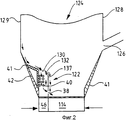
На фиг. 1 схематически показан вертикальный разрез циркуляционного реактора с псевдоожиженным слоем в соответствии с первым предпочтительным вариантом осуществления настоящего изобретения; на фиг. 2 и 3 - увеличенные разрезы нижней части камеры реактора с псевдоожиженным слоем в соответствии с другими вариантами осуществления изобретения; на фиг. 4 - в перспективе нижняя часть камеры реактора с псевдоожиженным слоем в соответствии с еще одним вариантом осуществления изобретения; на фиг. 5 и 6 - в увеличенном масштабе виды пустотелых стенок в камерах для частиц в соответствии с другими вариантами осуществления изобретения; на фиг. 7 - вид в перспективе с частичным разрезом пустотелой стенки, соответствующий фиг. 6. In FIG. 1 is a schematic vertical sectional view of a circulating fluidized bed reactor in accordance with a first preferred embodiment of the present invention; in FIG. 2 and 3 are enlarged sections of the lower part of the chamber of a fluidized bed reactor in accordance with other embodiments of the invention; in FIG. 4 is a perspective view of the lower part of the chamber of a fluidized bed reactor in accordance with yet another embodiment of the invention; in FIG. 5 and 6 are enlarged views of the hollow walls in particle chambers in accordance with other embodiments of the invention; in FIG. 7 is a perspective view in partial section of a hollow wall corresponding to FIG. 6.
На фиг. 1 показан циркуляционный реактор 10 с псевдоожиженным слоем, имеющий камеру реактора 12, обычную воздушную камеру 14 с решеткой 15 для подачи псевдоожижающего воздуха в камеру реактора, обычный сепаратор частиц 16, обычное выходное отверстие 18 для газа и обычный возвратный канал 20 для рециркуляции твердых частиц в камеру реактора 12. In FIG. 1 shows a circulating fluidized bed reactor 10 having a reactor chamber 12, a conventional air chamber 14 with a grill 15 for supplying fluidizing air to the reactor chamber, a conventional particle separator 16, a conventional gas outlet 18 and a conventional return channel 20 for recirculating solid particles into reactor chamber 12.
Камера для частиц 22 в соответствии с настоящим изобретением расположена в нижней части 24 камеры реактора 12. В соответствии с данным вариантом осуществления изобретения камера для частиц 12 соединена с входным отверстием 26 для частиц, рециркулирующих через возвратный канал 20. При таком способе относительно мелкозернистое вещество, поступающее из реактора 10, увлеченное газообразными продуктами горения, вводится в камеру для частиц 22. При этом может быть несколько входных отверстий для рециркулирующих частиц, и камера для частиц 22 может быть соединена с каждым из входных отверстий или только с одним или частью отверстий. Particle chamber 22 in accordance with the present invention is located at the bottom 24 of reactor chamber 12. According to this embodiment of the invention, particle chamber 12 is connected to particle inlet 26 recirculated through return duct 20. In this method, a relatively fine-grained material, coming from the reactor 10, carried away by the gaseous products of combustion, is introduced into the chamber for particles 22. There may be several inlets for recirculating particles, and the chamber for particles 22 can be l is connected to each of the inlets or to only one or part of the holes.
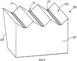
Дополнительно частицы, движущиеся вниз вдоль боковой стенки 28 камеры 12, захватываются пустотелой стенкой 30, образующей крышу для частиц 22. Отверстия 32 в пустотелой стенке 30 пропускают мелкие твердые частицы (см. стрелки 34) сквозь пустотелую стенку 30. Большие объекты (см. стрелки 36) опускаются вниз вдоль внешней поверхности 37 камеры для частиц 22. Частицы, поступающие во входное отверстие 26 и отверстия 32, вновь попадают в нижнюю часть камеры реактора через отверстия 38. Additionally, particles moving downward along the side wall 28 of the chamber 12 are trapped by the hollow wall 30 forming the roof for the particles 22. The holes 32 in the hollow wall 30 pass small solid particles (see arrows 34) through the hollow wall 30. Large objects (see arrows 36) fall down along the outer surface 37 of the particle chamber 22. Particles entering the inlet 26 and openings 32 again fall into the lower part of the reactor chamber through the
Отверстия 38 для вновь поступающих в камеру реактора частиц могут составлять при необходимости газовую пробку. Отверстия могут, например, представлять собой узкие пазы, расположенные друг над другом, причем каждый паз формирует L-образный клапан.
Поверхности для переноса тепла 40 расположены в камере для частиц 22. Поверхностями для переноса тепла 40 могут, например, быть поверхности испарителя или пароперегревателя. При помощи извлечения тепла из частиц, циркулирующих внутри камеры реактора 12, становится возможным получение существенного количества тепла даже при малых загрузках. The heat transfer surfaces 40 are located in the particle chamber 22. The heat transfer surfaces 40 may, for example, be the surfaces of an evaporator or superheater. By extracting heat from the particles circulating inside the chamber of the reactor 12, it becomes possible to obtain a significant amount of heat even at low loads.
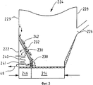
На фиг. 2 показан увеличенный вид нижней части 124 другого варианта выполнения камеры реактора в соответствии с изобретением. В этом варианте компоненты, сопоставимые с показанными на фиг. 1, обозначены теми же цифрами, но с добавлением перед ними цифры "1". В соответствии с этим вариантом осуществления изобретения, камера для частиц 122 расположена в положении, примыкающем к боковой стенке 129, противоположной боковой стенке 128, имеющей входное отверстие 126 для рециркулирующих тонких твердых частиц. Камера для частиц 122 расположена в нижней части 124 камеры реактора, имеющей наклонные огнеупорные стенки 41. Часть 42 огнеупорной стенки 41, примыкающая к боковой стенке 129, образует также боковую стенку камеры для тонкого вещества 122. Пустотелая стенка 130 и боковая стенка 137 камеры 122 предпочтительно также имеют огнеупорное покрытие. Пустотелая стенка 130 и боковая стенка 137 образуют перегородку между донным пространством 124 камеры реактора и пространством камеры для частиц 122. In FIG. 2 is an enlarged view of a
В циркуляционном реакторе с псевдоожиженным слоем плотный поток частиц движется по направлению вниз вдоль боковых стенок 41, и существенная часть частиц может проходить через камеру для частиц 122. Поверхности для переноса 140 преимущественно расположены в камере для частиц 122. Перенос тепла может управляться регулированием потока псевдоожижающего воздуха из воздушной камеры 46. Возвращение частиц в камеру реактора 112 через отверстия 138 также может контролироваться регулированием потока псевдоожижающего воздуха вблизи отверстий 138. In a circulating fluidized bed reactor, a dense particle flow moves downward along the
На фиг. 3 показан другой вариант осуществления изобретения. В этом варианте компоненты, сопоставимые с показанными на фиг. 2, обозначены теми же двузначными цифрами, но с добавлением перед ними цифры "2". В этом варианте осуществления изобретения камера для частиц сконструирована как часть наклонной огнеупорной стенки 242 нижней части камеры реактора 224. Входные отверстия 232, имеющие предопределенный диаметр или ширину, находятся в верхней части огнеупорной части стенки 242, причем эта верхняя часть посредством этого образует пустотелую стенку 230. Выходные отверстия 238 находятся в нижней части огнеупорной боковой стенки 241 для возвращения частиц в камеру реактора. Твердые частицы попадают в камеру для частиц через отверстия 232 и вновь поступают в камеру реактора через отверстия 238. Некоторые частицы при необходимости могут выпускаться из камеры 222 через выходное отверстие 48. In FIG. 3 shows another embodiment of the invention. In this embodiment, components comparable to those shown in FIG. 2 are denoted by the same two-digit numbers, but with the addition of the numbers “2” in front of them. In this embodiment, the particle chamber is designed as part of an inclined
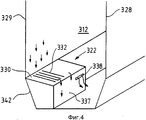
На фиг. 4 показан вид в перспективе еще одного варианта осуществления изобретения. В этом варианте компоненты, сопоставимые с показанными на фиг. 3, обозначены теми же двузначными цифрами, но с добавлением перед ними цифры "3". В этом варианте осуществления изобретения входные отверстия 332 и выходные отверстия 338 находятся в противоположных частях камеры для частиц 322 для осуществления хорошего смешивания там вещества. Выходные отверстия 338 пропускают твердые частицы из камеры для частиц 322 в камеру реактора 312. Уровень частиц в камере для частиц 322 зависит от расположения выходных отверстий 338 в стенке 337. In FIG. 4 is a perspective view of yet another embodiment of the invention. In this embodiment, components comparable to those shown in FIG. 3 are denoted by the same two-digit numbers, but with the addition of the numbers “3” in front of them. In this embodiment, the
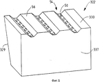
На фиг. 5 и 6 показаны в увеличенном масштабе виды пустотелых стенок 330 реактора, соответствующего фиг. 4. In FIG. 5 and 6 are enlarged views of the
Отверстия 50 в пустотелой стенке на фиг. 5 и пазы 52 на фиг. 6 выполнены в выемках 54 огнеупорного покрытия 56, покрывающего боковые стенки 337 и крышу 330 камеры для частиц 332. The
Стенки камеры для частиц 322 могут быть выполнены из панелей труб, например, водопроводных или испарительных труб, соединенных между собой ребрами. Выемки 54 в варианте, показанном на фиг. 5 и 6, выполнены так, что ребра между трубами оставлены свободными. Отверстия 50 или пазы 52 расположены в ребрах. The walls of the chamber for
В варианте осуществления изобретения, показанном на фиг. 6, пустотелая стенка 330 имеет наклонные, образующие гребни поверхности 57 между выемками 54 без заметных горизонтальных плоскостей. Таким образом, все частицы, движущиеся вниз на пустотелую стенку 330, направляются в пазы 52 на дне выемок 54. Частицы собираются с площади сечения, значительно большей, чем общая площадь пазов 52. Частицы собираются с площади сечения, по меньшей мере, в два раза большей, чем площадь общая пазов. Гребни 57 позволяют собирать и классифицировать частицы с большой площади без необходимости увеличения размеров и количества пазов 52. In the embodiment shown in FIG. 6, the
В других вариантах осуществления изобретения части верхней стенки (30, 130 и т.д.) камеры для частиц (22, 122 и т.д.) могут также образовывать направляющие стенки, направляющие частицы к отверстиям или пазам. In other embodiments of the invention, portions of the upper wall (30, 130, etc.) of the particle chamber (22, 122, etc.) may also form guide walls directing particles to the holes or grooves.
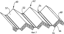
На фиг. 7 показан вид с частичным разрезом гребнеобразных элементов 57 пустотелой стенки 330, показанной на фигуре 6. Гребнеобразные элементы 57 выполнены в виде V-образных секций из трубчатых плит 60 и 62 с огнеупорным покрытием 63. Трубчатая плита выполнена из труб 64, соединенных ребрами 66. Секции из трубчатых плит расположены параллельно друг другу, при этом между каждыми двумя соседними секциями 60 и 62 оставлен паз 52. In FIG. 7 shows a partial sectional view of the comb-shaped
Площадь верхней собирающей стенки (30, 130, 230 и 330) камеры для частиц (22, 122, 222 и 322) в каждом варианте осуществления изобретения имеет площадь горизонтальной проекции A. Входные отверстия (32, 132, 232, 50 и 52), с другой стороны, имеют общую площадь B, которая составляет менее чем половину площади A. The area of the upper collecting wall (30, 130, 230 and 330) of the particle chamber (22, 122, 222 and 322) in each embodiment of the invention has a horizontal projection area A. Entrance openings (32, 132, 232, 50 and 52), on the other hand, have a total area B, which is less than half the area A.
Таким образом, будет видно, что в соответствии с изобретением созданы устройство и способ, обеспечивающие увеличенные возможности по сбору и классификации частиц, циркулирующих внутри реактора с псевдоожиженным слоем. Thus, it will be seen that in accordance with the invention, a device and method are provided that provide increased capabilities for collecting and classifying particles circulating inside a fluidized bed reactor.
Несмотря на то, что изобретение изложено в связи с вариантом изобретения, который сейчас может считаться наиболее приближенным к практике и предпочтительным, очевидно, что изобретение не ограничивается описанными вариантами, а, напротив, охватывает различные модификации и подобные устройства, соответствующие характеру и объему прилагаемой формулы изобретения. Despite the fact that the invention is set forth in connection with a variant of the invention, which may now be considered the closest to practice and preferred, it is obvious that the invention is not limited to the described options, but, on the contrary, covers various modifications and similar devices corresponding to the nature and scope of the attached claims inventions.
Claims (24)
Applications Claiming Priority (3)
| Application Number | Priority Date | Filing Date | Title |
|---|---|---|---|
| US041,571 | 1993-04-05 | ||
| US041.571 | 1993-04-05 | ||
| US08/041,571 US5332553A (en) | 1993-04-05 | 1993-04-05 | Method for circulating solid material in a fluidized bed reactor |
Publications (2)
| Publication Number | Publication Date |
|---|---|
| RU95117992A RU95117992A (en) | 1997-12-27 |
| RU2114690C1 true RU2114690C1 (en) | 1998-07-10 |
Family
ID=21917233
Family Applications (1)
| Application Number | Title | Priority Date | Filing Date |
|---|---|---|---|
| RU95117992A RU2114690C1 (en) | 1993-04-05 | 1994-03-28 | Method and device for circulation of substance in fluidized solids reactor |
Country Status (18)
| Country | Link |
|---|---|
| US (2) | US5332553A (en) |
| EP (1) | EP0692998B1 (en) |
| JP (1) | JP3326179B2 (en) |
| KR (1) | KR100321603B1 (en) |
| CN (1) | CN1105597C (en) |
| AT (1) | ATE155710T1 (en) |
| CA (1) | CA2158273C (en) |
| DE (1) | DE69404453T2 (en) |
| DK (1) | DK0692998T3 (en) |
| EE (1) | EE03189B1 (en) |
| ES (1) | ES2107199T3 (en) |
| FI (1) | FI119916B (en) |
| IL (1) | IL109065A (en) |
| PL (1) | PL176229B1 (en) |
| RU (1) | RU2114690C1 (en) |
| TW (1) | TW243492B (en) |
| UA (1) | UA27070C2 (en) |
| WO (1) | WO1994022570A1 (en) |
Cited By (2)
| Publication number | Priority date | Publication date | Assignee | Title |
|---|---|---|---|---|
| EA010170B1 (en) * | 2002-12-23 | 2008-06-30 | Оутокумпу Текнолоджи Ой | Method and plant for the conveyance of fine-grained solids |
| EA010276B1 (en) * | 2002-12-23 | 2008-08-29 | Оутокумпу Текнолоджи Ой | Method and apparatus for heat treatment in a fluidized bed |
Families Citing this family (24)
| Publication number | Priority date | Publication date | Assignee | Title |
|---|---|---|---|---|
| FR2690512B1 (en) * | 1992-04-27 | 1994-09-09 | Stein Industrie | Circulating fluidized bed reactor comprising external exchangers fed by internal recirculation. |
| FI93701C (en) * | 1993-06-11 | 1995-05-26 | Ahlstroem Oy | Method and apparatus for handling hot gases |
| FI93274C (en) * | 1993-06-23 | 1995-03-10 | Ahlstroem Oy | Method and apparatus for treating or recovering a hot gas stream |
| US5533471A (en) * | 1994-08-17 | 1996-07-09 | A. Ahlstrom Corporation | fluidized bed reactor and method of operation thereof |
| US5526775A (en) † | 1994-10-12 | 1996-06-18 | Foster Wheeler Energia Oy | Circulating fluidized bed reactor and method of operating the same |
| DE4439565C2 (en) * | 1994-11-05 | 1998-10-08 | Rethmann Lippewerk Recycling G | Valve device for the metered introduction of fine pockets into a fluidized bed reactor |
| US5522160A (en) * | 1995-01-05 | 1996-06-04 | Foster Wheeler Energia Oy | Fluidized bed assembly with flow equalization |
| US5567228A (en) * | 1995-07-03 | 1996-10-22 | Foster Wheeler Energy Corporation | System for cooling and cleaning synthesized gas using ahot gravel bed |
| US6139805A (en) * | 1995-11-15 | 2000-10-31 | Ebara Corporation | Fluidized-bed reactor |
| US6237541B1 (en) * | 2000-04-19 | 2001-05-29 | Kvaerner Pulping Oy | Process chamber in connection with a circulating fluidized bed reactor |
| US20040100902A1 (en) * | 2002-11-27 | 2004-05-27 | Pannalal Vimalchand | Gas treatment apparatus and method |
| EP1491253A1 (en) * | 2003-06-26 | 2004-12-29 | Urea Casale S.A. | Fluid bed granulation process and apparatus |
| FR2866695B1 (en) * | 2004-02-25 | 2006-05-05 | Alstom Technology Ltd | OXY-COMBUSTION BOILER WITH OXYGEN PRODUCTION |
| US7464669B2 (en) * | 2006-04-19 | 2008-12-16 | Babcock & Wilcox Power Generation Group, Inc. | Integrated fluidized bed ash cooler |
| US8129482B2 (en) * | 2008-02-27 | 2012-03-06 | Westlake Longview Corporation | Method of preventing or reducing polymer agglomeration on grid in fluidized-bed reactors |
| US8124697B2 (en) * | 2008-02-27 | 2012-02-28 | Westlake Longview Corporation | Method of preventing or reducing agglomeration on grid in fluidized-bed vessel |
| US9163830B2 (en) * | 2009-03-31 | 2015-10-20 | Alstom Technology Ltd | Sealpot and method for controlling a solids flow rate therethrough |
| US8434430B2 (en) * | 2009-09-30 | 2013-05-07 | Babcock & Wilcox Power Generation Group, Inc. | In-bed solids control valve |
| FI123548B (en) * | 2010-02-26 | 2013-06-28 | Foster Wheeler Energia Oy | Arrangement in a fluidized bed reactor |
| CN102840577B (en) * | 2011-06-23 | 2015-03-25 | 中国科学院工程热物理研究所 | Circulation fluidized bed boiler having compact type external dual fluidized bed heat exchanger |
| IN2015DN00277A (en) * | 2012-08-27 | 2015-06-12 | Southern Co | |
| US20170356642A1 (en) * | 2016-06-13 | 2017-12-14 | The Babcock & Wilcox Company | Circulating fluidized bed boiler with bottom-supported in-bed heat exchanger |
| CN106838889B (en) * | 2017-02-09 | 2019-09-27 | 重庆大学 | A kind of circulating fluidized bed boiler of the interior circulation ash heat exchanger of band |
| FI129147B (en) * | 2017-12-19 | 2021-08-13 | Valmet Technologies Oy | A circulating fluidized bed boiler with a loopseal heat exchanger |
Family Cites Families (17)
| Publication number | Priority date | Publication date | Assignee | Title |
|---|---|---|---|---|
| GB1397800A (en) * | 1972-09-01 | 1975-06-18 | Coal Industry Patents Ltd | Fluidised bed combusters |
| US3893426A (en) * | 1974-03-25 | 1975-07-08 | Foster Wheeler Corp | Heat exchanger utilizing adjoining fluidized beds |
| US4333909A (en) * | 1980-05-09 | 1982-06-08 | Foster Wheeler Energy Corporation | Fluidized bed boiler utilizing precalcination of acceptors |
| DE3688007D1 (en) * | 1985-06-12 | 1993-04-22 | Metallgesellschaft Ag | COMBUSTION DEVICE WITH CIRCULATING FLUID BED. |
| US4690802A (en) * | 1985-12-31 | 1987-09-01 | Exxon Research And Engineering Company | Apparatus for controlling the temperature in catalyst regeneration |
| CA1285375C (en) * | 1986-01-21 | 1991-07-02 | Takahiro Ohshita | Thermal reactor |
| SE457661B (en) * | 1986-06-12 | 1989-01-16 | Lars Axel Chambert | SEAT AND REACTOR FOR FLUIDIZED BOTTOM |
| US4896717A (en) * | 1987-09-24 | 1990-01-30 | Campbell Jr Walter R | Fluidized bed reactor having an integrated recycle heat exchanger |
| US4915061A (en) * | 1988-06-06 | 1990-04-10 | Foster Wheeler Energy Corporation | Fluidized bed reactor utilizing channel separators |
| FI84202C (en) * | 1989-02-08 | 1991-10-25 | Ahlstroem Oy | Reactor chamber in a fluidized bed reactor |
| SU1666863A1 (en) * | 1989-05-23 | 1991-07-30 | А.Г.Робул и А.И.Легенченко | Furnace with fluidized bed |
| US4951612A (en) * | 1989-05-25 | 1990-08-28 | Foster Wheeler Energy Corporation | Circulating fluidized bed reactor utilizing integral curved arm separators |
| US4947804A (en) * | 1989-07-28 | 1990-08-14 | Foster Wheeler Energy Corporation | Fluidized bed steam generation system and method having an external heat exchanger |
| US5005528A (en) * | 1990-04-12 | 1991-04-09 | Tampella Keeler Inc. | Bubbling fluid bed boiler with recycle |
| US5054436A (en) * | 1990-06-12 | 1991-10-08 | Foster Wheeler Energy Corporation | Fluidized bed combustion system and process for operating same |
| US5069171A (en) * | 1990-06-12 | 1991-12-03 | Foster Wheeler Agency Corporation | Fluidized bed combustion system and method having an integral recycle heat exchanger with a transverse outlet chamber |
| US5341766A (en) * | 1992-11-10 | 1994-08-30 | A. Ahlstrom Corporation | Method and apparatus for operating a circulating fluidized bed system |
-
1993
- 1993-04-05 US US08/041,571 patent/US5332553A/en not_active Expired - Lifetime
-
1994
- 1994-03-21 IL IL10906594A patent/IL109065A/en active IP Right Grant
- 1994-03-28 PL PL94310976A patent/PL176229B1/en not_active IP Right Cessation
- 1994-03-28 EP EP94910431A patent/EP0692998B1/en not_active Expired - Lifetime
- 1994-03-28 ES ES94910431T patent/ES2107199T3/en not_active Expired - Lifetime
- 1994-03-28 AT AT94910431T patent/ATE155710T1/en not_active IP Right Cessation
- 1994-03-28 RU RU95117992A patent/RU2114690C1/en not_active IP Right Cessation
- 1994-03-28 KR KR1019950704215A patent/KR100321603B1/en not_active IP Right Cessation
- 1994-03-28 UA UA95104402A patent/UA27070C2/en unknown
- 1994-03-28 DE DE69404453T patent/DE69404453T2/en not_active Expired - Lifetime
- 1994-03-28 CN CN94191693A patent/CN1105597C/en not_active Expired - Fee Related
- 1994-03-28 JP JP52170494A patent/JP3326179B2/en not_active Expired - Fee Related
- 1994-03-28 DK DK94910431.9T patent/DK0692998T3/en active
- 1994-03-28 CA CA002158273A patent/CA2158273C/en not_active Expired - Fee Related
- 1994-03-28 WO PCT/FI1994/000113 patent/WO1994022570A1/en active IP Right Grant
- 1994-04-05 US US08/222,862 patent/US5476639A/en not_active Expired - Lifetime
- 1994-04-12 TW TW083103245A patent/TW243492B/zh active
- 1994-08-10 EE EE9400030A patent/EE03189B1/en not_active IP Right Cessation
-
1995
- 1995-09-18 FI FI954374A patent/FI119916B/en not_active IP Right Cessation
Cited By (2)
| Publication number | Priority date | Publication date | Assignee | Title |
|---|---|---|---|---|
| EA010170B1 (en) * | 2002-12-23 | 2008-06-30 | Оутокумпу Текнолоджи Ой | Method and plant for the conveyance of fine-grained solids |
| EA010276B1 (en) * | 2002-12-23 | 2008-08-29 | Оутокумпу Текнолоджи Ой | Method and apparatus for heat treatment in a fluidized bed |
Also Published As
| Publication number | Publication date |
|---|---|
| EP0692998B1 (en) | 1997-07-23 |
| US5332553A (en) | 1994-07-26 |
| KR960701691A (en) | 1996-03-08 |
| ATE155710T1 (en) | 1997-08-15 |
| WO1994022570A1 (en) | 1994-10-13 |
| PL176229B1 (en) | 1999-05-31 |
| US5476639A (en) | 1995-12-19 |
| PL310976A1 (en) | 1996-01-22 |
| CA2158273C (en) | 2002-07-30 |
| DK0692998T3 (en) | 1998-03-02 |
| FI119916B (en) | 2009-05-15 |
| JP3326179B2 (en) | 2002-09-17 |
| DE69404453T2 (en) | 1997-12-18 |
| CN1105597C (en) | 2003-04-16 |
| KR100321603B1 (en) | 2002-06-20 |
| DE69404453D1 (en) | 1997-08-28 |
| EP0692998A1 (en) | 1996-01-24 |
| EE03189B1 (en) | 1999-06-15 |
| CA2158273A1 (en) | 1994-10-13 |
| JPH08508203A (en) | 1996-09-03 |
| IL109065A0 (en) | 1994-06-24 |
| ES2107199T3 (en) | 1997-11-16 |
| TW243492B (en) | 1995-03-21 |
| IL109065A (en) | 1999-06-20 |
| CN1120818A (en) | 1996-04-17 |
| FI954374A (en) | 1995-12-01 |
| UA27070C2 (en) | 2000-02-28 |
| FI954374A0 (en) | 1995-09-18 |
Similar Documents
| Publication | Publication Date | Title |
|---|---|---|
| RU2114690C1 (en) | Method and device for circulation of substance in fluidized solids reactor | |
| CA1305633C (en) | Method of burning carbonaceous materials in a fluidized bed reactor and a device for working the method | |
| CA1154335A (en) | Fluidized bed heat exchanger with water cooled air distributor and dust hopper | |
| RU2141870C1 (en) | Method and device for circulation of solid substance in reactor with fluidized bed | |
| EP0593229B1 (en) | Fluidized bed reactor utilizing a baffle system and method of operating same | |
| US4253425A (en) | Internal dust recirculation system for a fluidized bed heat exchanger | |
| CA1259859A (en) | Circulating fluidized bed reactor temperature control | |
| RU2232939C2 (en) | Circulating fluidized bed reactor | |
| JPH04227403A (en) | Fluidized-bed combustion apparatus and operating method thereof | |
| RU95117992A (en) | METHOD FOR SOLID CIRCULATION IN A REACTOR WITH A LIQUID PILLOW AND DEVICE FOR ITS IMPLEMENTATION | |
| EP0682761B1 (en) | Method and apparatus for recovering heat in a fluidized bed reactor | |
| EP0682760B1 (en) | Method and apparatus for operating a circulating fluidized bed reactor system | |
| RU2139136C1 (en) | Fluidized bed apparatus (versions), combination of this apparatus with combustion chamber or gasifier and method of treatment of solid granular material | |
| JPH0571708A (en) | Fluidized bed reactor and method of operating fluidized bed reactor utilizing improved particle removing device | |
| EP0667945B2 (en) | Method and apparatus for operating a circulating fluidized bed reactor system | |
| US5393315A (en) | Immersed heat exchanger in an integral cylindrical cyclone and loopseal | |
| JP2939338B2 (en) | Fluidized bed reactor and method for producing the same | |
| EP0082622A1 (en) | Fluidized bed combustion apparatus and method of carrying out fluidized bed combustion | |
| PT99750A (en) | METHOD OF CONTROL OF THE FURNACE TEMPERATURE FOR A FLUIDIZED BOILING COMBUSTION SYSTEM |
Legal Events
| Date | Code | Title | Description |
|---|---|---|---|
| MM4A | The patent is invalid due to non-payment of fees |
Effective date: 20110329 |