RU2088503C1 - Plastic box - Google Patents
Plastic box Download PDFInfo
- Publication number
- RU2088503C1 RU2088503C1 RU9393046335A RU93046335A RU2088503C1 RU 2088503 C1 RU2088503 C1 RU 2088503C1 RU 9393046335 A RU9393046335 A RU 9393046335A RU 93046335 A RU93046335 A RU 93046335A RU 2088503 C1 RU2088503 C1 RU 2088503C1
- Authority
- RU
- Russia
- Prior art keywords
- box
- segments
- row
- central rib
- flaps
- Prior art date
Links
- 239000004033 plastic Substances 0.000 title claims description 9
- 229920003023 plastic Polymers 0.000 title claims description 9
- 239000002991 molded plastic Substances 0.000 claims abstract description 4
- 239000003351 stiffener Substances 0.000 claims description 3
- 238000004519 manufacturing process Methods 0.000 abstract description 3
- 238000012856 packing Methods 0.000 abstract description 2
- 239000000126 substance Substances 0.000 abstract 1
- 238000001746 injection moulding Methods 0.000 description 4
- 239000000243 solution Substances 0.000 description 3
- 238000001125 extrusion Methods 0.000 description 2
- 239000000463 material Substances 0.000 description 2
- 238000000465 moulding Methods 0.000 description 2
- 229920001169 thermoplastic Polymers 0.000 description 2
- 239000004416 thermosoftening plastic Substances 0.000 description 2
- 230000002860 competitive effect Effects 0.000 description 1
- 238000005516 engineering process Methods 0.000 description 1
- 239000000945 filler Substances 0.000 description 1
- 235000012055 fruits and vegetables Nutrition 0.000 description 1
- 238000002347 injection Methods 0.000 description 1
- 239000007924 injection Substances 0.000 description 1
- 239000011159 matrix material Substances 0.000 description 1
- 239000002184 metal Substances 0.000 description 1
- 238000000034 method Methods 0.000 description 1
- 239000000123 paper Substances 0.000 description 1
- 230000035515 penetration Effects 0.000 description 1
- 239000002985 plastic film Substances 0.000 description 1
- 229920001187 thermosetting polymer Polymers 0.000 description 1
- 239000002699 waste material Substances 0.000 description 1
Images
Classifications
-
- B—PERFORMING OPERATIONS; TRANSPORTING
- B65—CONVEYING; PACKING; STORING; HANDLING THIN OR FILAMENTARY MATERIAL
- B65D—CONTAINERS FOR STORAGE OR TRANSPORT OF ARTICLES OR MATERIALS, e.g. BAGS, BARRELS, BOTTLES, BOXES, CANS, CARTONS, CRATES, DRUMS, JARS, TANKS, HOPPERS, FORWARDING CONTAINERS; ACCESSORIES, CLOSURES, OR FITTINGS THEREFOR; PACKAGING ELEMENTS; PACKAGES
- B65D11/00—Containers having bodies formed by interconnecting or uniting two or more rigid, or substantially rigid, components made wholly or mainly of plastics material
- B65D11/18—Containers having bodies formed by interconnecting or uniting two or more rigid, or substantially rigid, components made wholly or mainly of plastics material collapsible, i.e. with walls hinged together or detachably connected
- B65D11/1833—Containers having bodies formed by interconnecting or uniting two or more rigid, or substantially rigid, components made wholly or mainly of plastics material collapsible, i.e. with walls hinged together or detachably connected whereby all side walls are hingedly connected to the base panel
-
- B—PERFORMING OPERATIONS; TRANSPORTING
- B65—CONVEYING; PACKING; STORING; HANDLING THIN OR FILAMENTARY MATERIAL
- B65D—CONTAINERS FOR STORAGE OR TRANSPORT OF ARTICLES OR MATERIALS, e.g. BAGS, BARRELS, BOTTLES, BOXES, CANS, CARTONS, CRATES, DRUMS, JARS, TANKS, HOPPERS, FORWARDING CONTAINERS; ACCESSORIES, CLOSURES, OR FITTINGS THEREFOR; PACKAGING ELEMENTS; PACKAGES
- B65D5/00—Rigid or semi-rigid containers of polygonal cross-section, e.g. boxes, cartons or trays, formed by folding or erecting one or more blanks made of paper
- B65D5/001—Rigid or semi-rigid containers of polygonal cross-section, e.g. boxes, cartons or trays, formed by folding or erecting one or more blanks made of paper stackable
- B65D5/005—Separate or attached stacking elements
- B65D5/006—Separate corner posts and like elements
-
- B—PERFORMING OPERATIONS; TRANSPORTING
- B65—CONVEYING; PACKING; STORING; HANDLING THIN OR FILAMENTARY MATERIAL
- B65D—CONTAINERS FOR STORAGE OR TRANSPORT OF ARTICLES OR MATERIALS, e.g. BAGS, BARRELS, BOTTLES, BOXES, CANS, CARTONS, CRATES, DRUMS, JARS, TANKS, HOPPERS, FORWARDING CONTAINERS; ACCESSORIES, CLOSURES, OR FITTINGS THEREFOR; PACKAGING ELEMENTS; PACKAGES
- B65D2301/00—Details of blanks
- B65D2301/20—Details of blanks made of plastic material
Landscapes
- Engineering & Computer Science (AREA)
- Mechanical Engineering (AREA)
- Rigid Containers With Two Or More Constituent Elements (AREA)
- Stackable Containers (AREA)
- Containers Having Bodies Formed In One Piece (AREA)
- Assembled Shelves (AREA)
- Injection Moulding Of Plastics Or The Like (AREA)
Abstract
Description
Изобретение касается пластмассового ящика такого типа, который включает:
лист из формованной пластмассы с центральной частью, образующей основание ящика, и четырьмя складывающимися створками, шарнирно соединенными с центральной частью и формирующими боковые стенки ящика; и
четыре угловых стойки из пластмассы, каждая из которых имеет два желоба, в которые устанавливаются соответствующие боковые кромки двух соседних створок.The invention relates to a plastic box of this type, which includes:
a sheet of molded plastic with a central part forming the base of the box and four folding sashes pivotally connected to the central part and forming the side walls of the box; and
four corner posts made of plastic, each of which has two gutters, in which the corresponding side edges of two adjacent wings are installed.
У ящиков указанного типа, которые уже предложены, стойки предназначены для обеспечения боковых стенок ящиков жесткостью и поддержания веса штабелированных ящиков. Во французском патенте N 1.344.783 описывается ящик, изготовленный из материала на основе бумаги, боковые створки которого взаимно соединены угловыми элементами, изготовленными из металлических секций. For boxes of the indicated type, which have already been proposed, racks are designed to provide the side walls of the boxes with rigidity and to maintain the weight of the stacked boxes. French patent N 1.344.783 describes a box made of paper-based material, the side wings of which are mutually connected by corner elements made of metal sections.
Предпринимались многочисленные попытки изготовить пластмассовые стойки, которые обеспечивали устойчивое соединение с концами боковых створок ящика и которые были бы достаточно прочными, чтобы выдерживать вес штабелированных, т. е. установленных друг на друга ящиков. Пластмассовый ящик с боковыми стенками, шарнирно соединенными с основанием и скрепленные вместе с помощью угловых элементов (французский документ N 2.217.223. B 65 D 19/00). Кромки боковых стенок имеют Т-образную форму в поперечном сечении и предназначены для установки их в желобах подрезанного профиля углового элемента. Для получения стойки такого типа (французский документ 2.217.223) необходимо использовать пресс-формы, имеющие пресс-штоки, которые являются более сложными, деликатными и дорогими, чем простые состоящие из двух частей формы, с помощью которых, однако, нельзя получить подрезанные профили. Numerous attempts have been made to make plastic racks that provide a stable connection to the ends of the side flaps of the drawer and are strong enough to support the weight of stacked, that is, installed on top of each other drawers. Plastic box with side walls pivotally connected to the base and fastened together using corner elements (French document N 2.217.223. B 65 D 19/00). The edges of the side walls are T-shaped in cross section and are designed to be installed in the grooves of the trimmed profile of the corner element. To obtain a rack of this type (French document 2.217.223), it is necessary to use molds having press rods that are more complex, delicate and expensive than simple two-part molds, with which, however, cropped profiles cannot be obtained .
Патент США N 4.21.274 признает, что литьевое формование угловых стоек является очень дорогостоящим процессом из-за склонности пресс-форм и следовательно, предлагает выдавливание стоек для складывающихся ящиков. Однако, метод выдавливания не позволяет получить стойки с опорными соединениями, пригодными для бокового поддержания штабелированных ящиков. Поэтому, выдавленные стойки требуют дополнительно штифтовой формы элементов, получаемых литьевым формованием и обеспечивающих определенную степень внутреннего проникновения установленных друг на друга стоек. US Pat. No. 4.21.274 recognizes that injection molding of corner posts is a very expensive process because of the tendency of the molds and therefore offers extrusion of stands for folding drawers. However, the extrusion method does not allow to obtain racks with supporting joints suitable for lateral support of stacked boxes. Therefore, extruded racks additionally require a pin-shaped form of the elements obtained by injection molding and providing a certain degree of internal penetration of the racks mounted on top of each other.
Если посчитать, что рынок ежегодно требует производства ящиков порядка десятков миллионов штук/год и что каждый ящик требует четырех стоек, то будет понятно насколько важно найти решение, которое позволило бы изготавливать стойки как можно более экономично. If we consider that the market annually requires the production of boxes of the order of tens of millions of pieces / year and that each box requires four racks, then it will be clear how important it is to find a solution that would make it possible to produce racks as economically as possible.
Цель изобретения создание стойки, которая может изготавливаться с помощью технологии литья под давлением или литьевого формования с использованием простых состоящих из двух частей форм без подвижных элементов. В соответствии с изобретением эта цель достигается благодаря тому, что, каждая стойка включает:
центральное ребро с продольной осью, перпендикулярной к основанию ящика;
первый и второй ряды сегментов, выполненных за одно целое с ребром и имеющих соответствующие опорные поверхности, образующие противоположные стенки желобов для размещения боковых кромок створок, при этом сегменты каждого ряда разделены пространствами, высота которых вдоль продольной оси ребра равна или больше, чем высота по той же оси сегментов противоположного ряда, причем опорные поверхности сегментов каждого ряда обращены к простраствам между сегментами противоположного ряда.The purpose of the invention is the creation of a rack, which can be manufactured using injection molding or injection molding technology using simple two-part molds without movable elements. In accordance with the invention, this goal is achieved due to the fact that each rack includes:
central rib with a longitudinal axis perpendicular to the base of the box;
the first and second rows of segments made in one piece with the rib and having corresponding supporting surfaces forming opposite walls of the grooves to accommodate the lateral edges of the flaps, while the segments of each row are separated by spaces whose height along the longitudinal axis of the rib is equal to or greater than the height the same axis of the segments of the opposite row, and the supporting surfaces of the segments of each row facing the spaces between the segments of the opposite row.
Техническое решение по изобретению обеспечивает устойчивое механическое соединение между боковыми стенками ящика и стойками без необходимости выполнять в них желоба подрезанного профиля. Следовательно, становится возможным использовать простые состоящие из двух частей формы, которые могут изготавливать очень большое число деталей, например, 25-50 за каждый формовочный цикл. Это решение позволяет также использовать рециркулированные и наполненные термопластмассы. Благодаря решению проблемы стоимости стоек, настоящее изобретение делает пластмассовые ящики конкурентоспособными с деревянными и картонными ящиками, которые в настоящее время широко используются для упаковки фруктов и овощей. The technical solution according to the invention provides a stable mechanical connection between the side walls of the box and the racks without the need to run in them the grooves of the trimmed profile. Therefore, it becomes possible to use simple two-part molds that can produce a very large number of parts, for example, 25-50 for each molding cycle. This solution also allows the use of recycled and filled thermoplastics. By solving the cost problem of racks, the present invention makes plastic crates competitive with wooden and cardboard crates, which are currently widely used for packing fruits and vegetables.
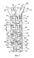
На фиг. 1 представлен перспективный вид ящика по изобретению; на фиг. 2
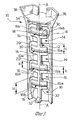
перспективный вид в увеличенном масштабе стойки, выполненный по стрелке II на фиг. 1; на фиг. 3 перспективный вид стойки, выполненный по стрелке III на фиг. 2; на фиг. 4 и 5 представлены виды в сечениях, выполненных по линиям IV-IV и V-V на фиг. 1.In FIG. 1 is a perspective view of a box according to the invention; in FIG. 2
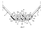
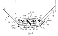
perspective view on an enlarged scale of the rack, made along arrow II in FIG. one; in FIG. 3 is a perspective view of the rack, made along arrow III in FIG. 2; in FIG. 4 and 5 are sectional views taken along lines IV-IV and VV of FIG. one.
Как показано на фиг. 1, лист 1 из пластмассы образован прямоугольной центральной частью 2, к каждой стороне которой шарнирно прикреплена складывающаяся створка 4. Центральная часть 2 образует основание ящика, а створки 4 образуют его боковые стенки. Створки 4 шарнирно соединены с центральной частью 2 с помощью углублений 6, глубина которых меньше, чем толщина остальной части листа 1. Центральная часть 2 и створки 4 имеют ребра жесткости 8. As shown in FIG. 1, a plastic sheet 1 is formed by a rectangular central part 2, on each side of which a
Лист 2 изготавливается прямым формованием материала, состоящего из термопластичной матрицы и наполнителей, выполненных из отходов, которые трудно возвращаются в повторный цикл, например, термореактивные пластмассы. Sheet 2 is made by direct molding of a material consisting of a thermoplastic matrix and fillers made from waste that is difficult to return to the recycle cycle, for example, thermosetting plastics.
Створки 4 перемещаются из положений, в которых они расположены параллельно центральной части 2, в положении, в которых они перпендикулярны к части 2. Створки 4 удерживаются в их вторых положениях с помощью четырех угловых стоек 10 из пластмассы, только одна из которых показана на фиг. 1. The
Как показано более подробно на фиг. 2 5, стойка 10 представляет собой цельный элемент, изготовленный из пластмассы литьевым формованием, и имеет центральное ребро 12, продольная ось А которого перпендикулярна к основанию 2 ящика. Первый и второй ряды сегментов 14 и 16 соответственно выступают с центрального ребра 12. Каждый сегмент образован двумя частями 14a, 14b и 16a, 16b, расположенными симметрично относительно центрального ребра 12. Сегменты 14 первого ряда соединены с парой боковых ребер 18, параллельных центральному ребру 12. Сегменты 14 первого ряда разделены пространствами 20, высота H которых на оси А равна или больше, чем высота h сегментов 16 второго ряда. Сегменты 16 второго ряда обращены к пространствам 20 между сегментами 14 первого ряда. Такое расположение сегментов позволяет изготавливать стойки 10 с помощью состоящей из двух частей формы без пресс-штоков и т.п. As shown in more detail in FIG. 2 5, the
Как показано на фиг. 4 и 5, сегменты 14, 16 имеют соответствующие параллельные опорные поверхности 22, 24, между которыми образуются два желоба для размещения соответствующих боковых кромок 26 двух соседних створок 4. Боковые кромки 26 створок 4 наклонены к створкам 4 под углом В, который больше, чем 90o. Опорные поверхности 22 сегментов 14 первого ряда наклонены аналогично наклону кромок 26 створок 4.As shown in FIG. 4 and 5,
Ребро жесткости 28, 30 выступает с задней поверхности каждого сегмента 1, 16 поперек центральному ребру 12. Как показано на фиг. 3, центральное ребро 12 имеет выступ 32, который служит для того, чтобы упираться в основание 2 ящика. Как показано на фиг. 3, центральное ребро 12 и боковые ребра 8 выполнены за одно целое с плоским опорным основанием 34, которое перпендикулярно к оси А ребра 12. Основание 34 образует опору для соответствующей стойки установленного сверху ящика. Две расходящиеся стенки 36 выступают с основания 34 для бокового ограничения и направления угла штабелированного ящика. The
Один и тот же тип стойки 10 может использоваться как для ящиков с высокими боковыми стенками, типа показанного на фиг. 1 так и для ящиков с низкими боковыми стенками, вполовину меньшими высоты стойки 10. The same type of
Claims (7)
Applications Claiming Priority (2)
| Application Number | Priority Date | Filing Date | Title |
|---|---|---|---|
| EP92830299A EP0573729B1 (en) | 1992-06-09 | 1992-06-09 | Plastic collapsible box |
| EP92830299.1 | 1992-06-09 |
Publications (2)
| Publication Number | Publication Date |
|---|---|
| RU93046335A RU93046335A (en) | 1996-02-20 |
| RU2088503C1 true RU2088503C1 (en) | 1997-08-27 |
Family
ID=8212119
Family Applications (1)
| Application Number | Title | Priority Date | Filing Date |
|---|---|---|---|
| RU9393046335A RU2088503C1 (en) | 1992-06-09 | 1993-06-08 | Plastic box |
Country Status (7)
| Country | Link |
|---|---|
| US (1) | US5279438A (en) |
| EP (1) | EP0573729B1 (en) |
| JP (1) | JPH06286749A (en) |
| CN (1) | CN1035667C (en) |
| DE (1) | DE69213222T2 (en) |
| ES (1) | ES2092082T3 (en) |
| RU (1) | RU2088503C1 (en) |
Cited By (1)
| Publication number | Priority date | Publication date | Assignee | Title |
|---|---|---|---|---|
| WO2006116824A2 (en) | 2005-04-22 | 2006-11-09 | Kamran Mahmudov | Polymer box |
Families Citing this family (16)
| Publication number | Priority date | Publication date | Assignee | Title |
|---|---|---|---|---|
| AU2400295A (en) * | 1993-12-30 | 1995-07-17 | Hae Soon Oh | Folding and unfolding box |
| US5638973A (en) * | 1996-05-09 | 1997-06-17 | Western Poly Corporation | Storage container with interlocking corner members |
| ES1041715Y (en) * | 1999-01-12 | 1999-11-16 | Romeu Juan Luis Ripolles | FOLDING BOX. |
| CA2362282C (en) * | 1999-02-09 | 2008-06-17 | Alexander John Bronkhorst | Collapsible crate and associated connecting means |
| ES2169661B1 (en) * | 2000-05-04 | 2003-04-01 | Romeu Juan Luis Ripolles | PACKING BOX |
| IT250229Y1 (en) * | 2000-06-02 | 2003-07-28 | Meccaniche Luigi Bander A S P | HIGH STABILITY MODULAR BOX |
| EP1943150B1 (en) * | 2005-11-03 | 2012-01-04 | Gilroy Clements Mcalpine | Reinforcing corner post for container |
| GB2470365A (en) * | 2009-05-19 | 2010-11-24 | Khaled Ouchfoun | Margarine tub with gusseted folding access flap |
| US8997993B2 (en) * | 2011-07-27 | 2015-04-07 | E.M.I. Enterprises, Inc. | Stackable envelope trays |
| DE102011056463B4 (en) * | 2011-12-15 | 2015-11-05 | Rittal Gmbh & Co. Kg | Housing for receiving components, in particular electronic assemblies, components and the like |
| CN202750889U (en) * | 2012-08-07 | 2013-02-27 | 张综源 | Folding assembled case |
| DE102013008898A1 (en) * | 2013-05-27 | 2014-11-27 | Webasto SE | vehicle roof |
| CN105836254B (en) * | 2016-05-24 | 2018-12-07 | 上海鸿研物流技术有限公司 | Folding carton |
| WO2018134652A1 (en) * | 2017-01-23 | 2018-07-26 | Wenco S.A. | Plastic container comprising a bottom in which the width and thickness vary according to the position of the strip on the bottom base and based on the forces to which the container is subjected |
| ES2876224T3 (en) * | 2018-12-21 | 2021-11-12 | Schoeller Allibert Gmbh | Container with collapsible bottom section |
| US12103731B2 (en) * | 2020-08-03 | 2024-10-01 | Radius Outfitters | Modular container system with corner couplers |
Family Cites Families (16)
| Publication number | Priority date | Publication date | Assignee | Title |
|---|---|---|---|---|
| US299363A (en) * | 1884-05-27 | Vehicle-spring | ||
| US778809A (en) * | 1902-06-07 | 1904-12-27 | John S Stokes | Stay-strip for boxes. |
| US2993633A (en) * | 1960-03-17 | 1961-07-25 | Robert G Keller | Combined folding box and article support |
| FR1304633A (en) * | 1961-10-28 | 1962-09-21 | Removable box or crate, in particular for packaging | |
| US3223309A (en) * | 1964-03-20 | 1965-12-14 | Chiorri Bartolomeo | Composable container structure consisting of sheet-like material |
| GB1169727A (en) * | 1965-12-21 | 1969-11-05 | C A Parsons Of Ireland Ltd | Improvements in and relating to Angle Shaped Supporting Members for use with Collapsible Boxes and Crates and Boxes and Crates Constructed in Combination with such Members |
| DE1611004A1 (en) * | 1967-01-27 | 1970-09-03 | Waldhof Zellstoff Fab | Rise for fruit, vegetables or the like and device for their installation |
| US3401814A (en) * | 1967-03-07 | 1968-09-17 | Collapsible Container Corp | Collapsible shipping container |
| GB1247340A (en) * | 1967-11-21 | 1971-09-22 | Marcan Betty M | Trays for garden produce |
| GB1531234A (en) * | 1974-10-30 | 1978-11-08 | Lb Ltd | Construction of enclosures or containers |
| NL172018C (en) * | 1976-11-18 | Tektronix Inc | STRIP SHAPED CONNECTION ELEMENT. | |
| IL56316A (en) * | 1978-01-06 | 1980-11-30 | Lionel Leonard | Boxes |
| US4167353A (en) * | 1978-07-12 | 1979-09-11 | The Mead Corporation | Display device |
| GB2108573B (en) * | 1981-10-27 | 1985-01-16 | Unilever Plc | Corner clip |
| US4591065A (en) * | 1984-09-25 | 1986-05-27 | Foy Dennis M | Foldable container assembly |
| US4673087A (en) * | 1985-11-04 | 1987-06-16 | Peninsula Plastics Co., Inc. | Collapsable, reusable container system |
-
1992
- 1992-06-09 ES ES92830299T patent/ES2092082T3/en not_active Expired - Lifetime
- 1992-06-09 DE DE69213222T patent/DE69213222T2/en not_active Expired - Fee Related
- 1992-06-09 EP EP92830299A patent/EP0573729B1/en not_active Expired - Lifetime
-
1993
- 1993-06-01 US US08/069,938 patent/US5279438A/en not_active Expired - Lifetime
- 1993-06-08 CN CN93108270A patent/CN1035667C/en not_active Expired - Fee Related
- 1993-06-08 JP JP5137464A patent/JPH06286749A/en active Pending
- 1993-06-08 RU RU9393046335A patent/RU2088503C1/en active
Non-Patent Citations (1)
| Title |
|---|
| 1. Патент Франции N 2217223, кл. B 65 D 19/00, 1974. 2. Патент США N 4210274, кл. B 65 D 5/42, 1980. * |
Cited By (2)
| Publication number | Priority date | Publication date | Assignee | Title |
|---|---|---|---|---|
| WO2006116824A2 (en) | 2005-04-22 | 2006-11-09 | Kamran Mahmudov | Polymer box |
| MD3778G2 (en) * | 2005-04-22 | 2009-07-31 | Камран МАХМУДОВ | Polymer box |
Also Published As
| Publication number | Publication date |
|---|---|
| DE69213222D1 (en) | 1996-10-02 |
| EP0573729B1 (en) | 1996-08-28 |
| CN1035667C (en) | 1997-08-20 |
| CN1081645A (en) | 1994-02-09 |
| DE69213222T2 (en) | 1997-01-23 |
| ES2092082T3 (en) | 1996-11-16 |
| JPH06286749A (en) | 1994-10-11 |
| US5279438A (en) | 1994-01-18 |
| EP0573729A1 (en) | 1993-12-15 |
Similar Documents
| Publication | Publication Date | Title |
|---|---|---|
| RU2088503C1 (en) | Plastic box | |
| CN1038570C (en) | Foldable vegetable box with side walls made of plastic | |
| US4002261A (en) | Construction of panels, enclosures or containers | |
| US3917108A (en) | Plastic tray and method of making same | |
| US4988003A (en) | Stackable tray carrying units | |
| US2718326A (en) | Tray with variable number of uniform size cells | |
| US3145904A (en) | Blanks for ready erection into box-like containers | |
| US20020092818A1 (en) | Beam structures for shelving apparatus | |
| US3544021A (en) | Double-wall blow molded carton | |
| US4234089A (en) | Microfiche tray | |
| DE59206146D1 (en) | Box-shaped container made of plastic | |
| RU93046335A (en) | PLASTIC BOX | |
| US3528583A (en) | Collapsible poultry coop | |
| ATE33371T1 (en) | STACKABLE CARRIER OR BOX FOR GOODS OR OBJECTS. | |
| GB1203403A (en) | A set of boxes of different sizes | |
| EP0524658A1 (en) | Plastic pallet | |
| US6076692A (en) | Receptacle with variable dimensions | |
| US3383027A (en) | Unitary collapsible partition | |
| DE69702744T2 (en) | Carrier element, such as a pallet | |
| NL2020482B1 (en) | A combi box for the transport and storage of goods | |
| NL1005834C2 (en) | Plastic pallet. | |
| ATE79211T1 (en) | PLASTIC CHEESE MOLD WITH DRAINAGE GROOVES MOLDED BY INJECTION DURING THE MANUFACTURE OF THE SIDE PANEL. | |
| KR100478752B1 (en) | Sectional display stand and making method thereof | |
| CN1452575A (en) | High-stability composable case | |
| ATE9884T1 (en) | PLASTIC TRANSPORT BOX, ESPECIALLY FOR FRUITS. |