RU2080503C1 - Shaft stuffing arrangement - Google Patents
Shaft stuffing arrangement Download PDFInfo
- Publication number
- RU2080503C1 RU2080503C1 RU95114134A RU95114134A RU2080503C1 RU 2080503 C1 RU2080503 C1 RU 2080503C1 RU 95114134 A RU95114134 A RU 95114134A RU 95114134 A RU95114134 A RU 95114134A RU 2080503 C1 RU2080503 C1 RU 2080503C1
- Authority
- RU
- Russia
- Prior art keywords
- pressure
- grooves
- axially movable
- ring
- seal
- Prior art date
Links
- 238000007789 sealing Methods 0.000 claims abstract description 88
- 239000003381 stabilizer Substances 0.000 claims abstract description 27
- 230000006835 compression Effects 0.000 claims description 5
- 238000007906 compression Methods 0.000 claims description 5
- 230000002093 peripheral effect Effects 0.000 claims description 3
- 230000013011 mating Effects 0.000 abstract description 6
- 238000005192 partition Methods 0.000 abstract description 3
- 230000000694 effects Effects 0.000 abstract description 2
- 238000012856 packing Methods 0.000 abstract 2
- 238000005553 drilling Methods 0.000 abstract 1
- 239000000126 substance Substances 0.000 abstract 1
- 238000001816 cooling Methods 0.000 description 4
- 238000009826 distribution Methods 0.000 description 4
- 230000002441 reversible effect Effects 0.000 description 4
- 230000007423 decrease Effects 0.000 description 2
- 238000010586 diagram Methods 0.000 description 2
- 238000009434 installation Methods 0.000 description 2
- 239000000463 material Substances 0.000 description 2
- 238000000034 method Methods 0.000 description 2
- OKTJSMMVPCPJKN-UHFFFAOYSA-N Carbon Chemical compound [C] OKTJSMMVPCPJKN-UHFFFAOYSA-N 0.000 description 1
- 229910052581 Si3N4 Inorganic materials 0.000 description 1
- 229910045601 alloy Inorganic materials 0.000 description 1
- 239000000956 alloy Substances 0.000 description 1
- 238000005452 bending Methods 0.000 description 1
- 230000015572 biosynthetic process Effects 0.000 description 1
- 239000012141 concentrate Substances 0.000 description 1
- 238000013016 damping Methods 0.000 description 1
- 229910002804 graphite Inorganic materials 0.000 description 1
- 239000010439 graphite Substances 0.000 description 1
- 238000000227 grinding Methods 0.000 description 1
- 230000017525 heat dissipation Effects 0.000 description 1
- 230000002706 hydrostatic effect Effects 0.000 description 1
- 230000007774 longterm Effects 0.000 description 1
- 238000004519 manufacturing process Methods 0.000 description 1
- 238000005555 metalworking Methods 0.000 description 1
- 238000003801 milling Methods 0.000 description 1
- 230000000737 periodic effect Effects 0.000 description 1
- 238000004321 preservation Methods 0.000 description 1
- HBMJWWWQQXIZIP-UHFFFAOYSA-N silicon carbide Chemical compound [Si+]#[C-] HBMJWWWQQXIZIP-UHFFFAOYSA-N 0.000 description 1
- 229910010271 silicon carbide Inorganic materials 0.000 description 1
- HQVNEWCFYHHQES-UHFFFAOYSA-N silicon nitride Chemical compound N12[Si]34N5[Si]62N3[Si]51N64 HQVNEWCFYHHQES-UHFFFAOYSA-N 0.000 description 1
- 238000000992 sputter etching Methods 0.000 description 1
- 238000004227 thermal cracking Methods 0.000 description 1
- UONOETXJSWQNOL-UHFFFAOYSA-N tungsten carbide Chemical compound [W+]#[C-] UONOETXJSWQNOL-UHFFFAOYSA-N 0.000 description 1
Images

Landscapes
- Sealing Devices (AREA)
Abstract
Description
Изобретение относится к уплотнительной технике и может быть использовано в турбокомпрессорах различного назначения для уплотнения вращающихся валов. The invention relates to a sealing technique and can be used in turbochargers for various purposes for sealing rotating shafts.
В известных конструкциях уплотнений вращающихся валов [1, 2] уплотнение вала содержит установленное герметично в корпусе и разделяющее полости высокого и низкого давления аксиально-подвижное уплотнительное кольцо с нажимной пружиной и вторичным уплотнением, размещенным в кольцевой проточке корпуса, и закрепленное на валу вращающееся уплотнительное кольцо, на торцовой поверхности которого выполнены уплотнительная перегородка и расположенные на периферии против направления вращения спиральные канавки. Однако такие конструкции уплотнений вала имеют низкую надежность, поскольку обеспечивают лишь однонаправленное вращение вала, не обеспечивают хорошую ремонтопригодность и высокую долговечность трущейся пары, не позволяют осуществить эффективное охлаждение контактных поверхностей, то есть общая надежность конструкции уплотнения очень низкая. In known designs of rotary shaft seals [1, 2], the shaft seal comprises an axially movable sealing ring sealed in the housing and separating the high and low pressure cavities with a compression spring and a secondary seal located in the annular groove of the housing, and a rotating sealing ring fixed to the shaft , on the end surface of which a sealing partition is made and spiral grooves located on the periphery against the direction of rotation. However, such designs of shaft seals have low reliability because they provide only unidirectional rotation of the shaft, do not provide good maintainability and high durability of the rubbing pair, do not allow for effective cooling of contact surfaces, that is, the overall reliability of the seal design is very low.
Наиболее близким к заявляемому изобретению по технической сущности и достигаемому положительному технико-экономическому эффекту является конструкция уплотнения вала принятая в качестве прототипа, содержащая установленное герметично в корпусе и разделяющее полости высокого и низкого давления аксиально-подвижное уплотнительное кольцо с нажимной пружиной и вторичным уплотнением, размещенным в кольцевой проточке корпуса, и закрепленное на валу вращающееся уплотнительное кольцо, на торцовой поверхности которого выполнены уплотнительная перегородка и расположенные на периферии против направления вращения спиральные канавки [3] Однако такая конструкция уплотнения вала имеет низкую надежность, т.к. не позволяют осуществлять реверсивное направление вращения вала, не обеспечивают хорошее охлаждение сопрягаемых уплотнительных поверхностей аксиально-подвижного и вращающегося уплотнительных колец. The closest to the claimed invention in terms of technical nature and the achieved positive technical and economic effect is the shaft seal design adopted as a prototype, containing an axially movable sealing ring with a pressure spring and a secondary seal installed in the housing sealed in the housing and separating the high and low pressure cavities an annular groove of the housing, and a rotating sealing ring fixed to the shaft, on the end surface of which there are seals Naya septum and placed on the periphery against the direction of rotation of the spiral grooves [3] However, such a shaft seal structure has a low reliability, because they do not allow the reverse direction of rotation of the shaft, they do not provide good cooling of the mating sealing surfaces of the axially movable and rotating sealing rings.
Целью изобретения является повышение надежности работы уплотнения вала при длительной эксплуатации и оптимизации его характеристик путем оптимизации распределения давления в уплотнительном зазоре за счет выбора оптимальной формы спиральных канавок, реализации возможности реверсивного вращения вала, снижения термонагруженности колец трущейся пары. The aim of the invention is to increase the reliability of the shaft seal during long-term operation and to optimize its characteristics by optimizing the pressure distribution in the sealing gap by choosing the optimal shape of the spiral grooves, realizing the possibility of reverse shaft rotation, and reducing the thermal loading of the friction pair rings.
Это достигается тем, что уплотнение вала содержит установленные герметично в корпусе и разделяющее полости высокого и низкого давления аксиально-подвижное уплотнительное кольцо с нажимной пружиной и вторичным уплотнением, размещенным в кольцевой проточке корпуса, и закрепленное на валу вращающееся уплотнительное кольцо, на торцовой поверхности которого выполнены уплотнительная перегородка и расположенные на периферии против направления вращения спиральные канавки, согласно изобретению торцовая поверхность аксиально-подвижного уплотнительного кольца выполнена по крайней мере с фасками на одной из ограничивающих цилиндрических поверхностей, а ответная торцовая поверхность вращающегося уплотнительного кольца дополнительно снабжена концентраторами и/или стабилизаторами давления, при этом концентраторы давления могут быть выполнены в виде выступов, размещенных в спиральных канавках, выпуклой стороной обращенных к противоположной (задней) стороне канавок. Стабилизаторы давления, кроме того, могут быть выполнены в виде углублений, расположенный на уплотнительной перегородке вдоль продольных образующих задних стенок спиральных канавок, или стабилизаторы давления могут быть выполнены в виде наклонных проточных каналов, соединяющих донные части спиральных канавок с полостью низкого давления. Наклонные проточные каналы могут быть также связаны между собой кольцевой уравнительной канавкой. Стабилизаторы давления могут быть также выполнены в виде по крайней мере двух уравнительных канавок, связанных между собой и донными частями спиральных канавок радиальными перепускными каналами. стабилизаторы и концентраторы давления могут быть также выполнены в виде совмещенных с основными спиральными канавками дополнительны спиральных канавок, расположенных на торцовой поверхности вращающегося уплотнительного кольца под равным углом с направлением основных спиральных канавок, но направленных в противоположную сторону, причем наружные и донные части основных и дополнительных канавок выполнены с наложением друг на друга. Концентраторы давления также могут быть выполнены в виде наклонных каналов, входная часть которых расположена со стороны внутренней уплотнительной поверхности вращающегося уплотнительного кольца или полости низкого давления. Аксиально-подвижное уплотнительное кольцо снабжено, кроме того, дополнительным центрирующим пояском, выполненным в виде цилиндрического выступа на наружной периферийной поверхности аксиально-подвижного уплотнительного кольца. При этом наружная центрирующая поверхность цилиндрического выступа может быть выполнена в виде части сферы. Цилиндрические выступы, кроме того, могут быть снабжены пазами в виде части цилиндра, а в корпусе установлены штифты, диаметр которых меньше диаметра образующих пазов. Кольцевая проточка в корпусе под вторичное уплотнение аксиально-подвижного уплотнительного кольца может быть выполнена конической или по сфере. This is achieved by the fact that the shaft seal contains an axially movable sealing ring with a compression spring and a secondary seal located in the annular groove of the housing, and a rotating sealing ring fixed to the shaft, on the end surface of which is made hermetically sealed in the housing and separating the high and low pressure cavities the sealing wall and the spiral grooves located on the periphery against the direction of rotation, according to the invention, the end surface of the axially movable the filling ring is made at least with chamfers on one of the limiting cylindrical surfaces, and the counter end surface of the rotating sealing ring is additionally equipped with concentrators and / or pressure stabilizers, while the pressure concentrators can be made in the form of protrusions placed in spiral grooves with the convex side facing to the opposite (back) side of the grooves. Pressure stabilizers, in addition, can be made in the form of recesses located on the sealing wall along the longitudinal generatrix of the rear walls of the spiral grooves, or pressure stabilizers can be made in the form of inclined flow channels connecting the bottom of the spiral grooves with a low pressure cavity. Inclined flow channels can also be interconnected by an annular equalization groove. Pressure stabilizers can also be made in the form of at least two equalizing grooves, interconnected with the bottom parts of the spiral grooves by radial bypass channels. stabilizers and pressure concentrators can also be made in the form of additional spiral grooves combined with the main spiral grooves, located on the end surface of the rotating sealing ring at an equal angle with the direction of the main spiral grooves, but directed in the opposite direction, with the outer and bottom parts of the main and additional grooves made superimposed on each other. Pressure concentrators can also be made in the form of inclined channels, the inlet of which is located on the side of the inner sealing surface of the rotating sealing ring or low-pressure cavity. The axially movable sealing ring is also provided with an additional centering belt made in the form of a cylindrical protrusion on the outer peripheral surface of the axially movable sealing ring. In this case, the outer centering surface of the cylindrical protrusion can be made in the form of part of a sphere. The cylindrical protrusions, in addition, can be provided with grooves in the form of a part of the cylinder, and pins are installed in the housing, the diameter of which is less than the diameter of the forming grooves. An annular groove in the housing for the secondary seal of the axially movable sealing ring can be made conical or in a sphere.
Таким образом, предлагаемая конструкция уплотнения вала обладает следующими существенными отличительными признаками. Thus, the proposed design of the shaft seal has the following significant distinguishing features.
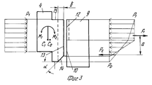
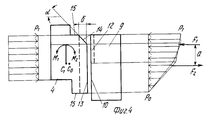
Торцовая поверхность аксиально-подвижного кольца выполнена по крайней мере на одной из ограничивающих цилиндрических поверхностей с фасками, что позволяет обеспечить сохранение постоянного уплотнительного зазора по всей части радиуса вне зависимости от того, какая форма уплотнительного зазора ожидается (конфузорная или диффузорная). Это объясняется тем, что конфигурация уплотнительного элемента при нормальных условиях работы (без перекосов) обеспечивает отсутствие осесимметричных деформаций на рабочем режиме. То есть момент относительно центра сечения Со равен нулю, однако в процессе эксплуатации в результате износа или периодической притирки торцовой уплотнительной поверхности осевой размер уплотнительного элемента уменьшается на величину S. При этом центр сечения смещается в точку С1, относительно которой возникает момент М1 (его составляющие F1 и F2), приводящий к осесимметричной деформации уплотнительного элемента, перекосу, образованию конфузорного (фиг. 3, 4), уплотняющего зазора, что, в свою очередь, приводит к интенсивному износу уплотняющего элемента. Выполнение фаски изменяет эпюру давления в зазоре и таким образом обеспечивает появление момента М2, смещенного относительно центра сечения С1, противоположного и равного М1. Равенство противоположно направленных моментов обеспечивает их уравновешивание, и в результате торцовые уравнительные поверхности остаются параллельными между собой, устраняются перекосы и исключается износ, при этом необходимая величина фаски определяется расчетным путем. В результате происходит увеличение надежности из-за сохранения параллельности сопрягаемых поверхностей в зазоре и отсутствия контакта поверхностей за счет автоматического уравновешивания изгибающих моментов, возникающих в процессе эксплуатации из-за износа уплотнительных колец. The end surface of the axially movable ring is made on at least one of the limiting cylindrical surfaces with chamfers, which allows to maintain a constant sealing gap over the entire radius, regardless of what form of the sealing gap is expected (confuser or diffuser). This is because the configuration of the sealing element under normal operating conditions (without distortions) ensures the absence of axisymmetric deformations in the operating mode. That is, the moment relative to the center of the section of Co is zero, however, during operation, as a result of wear or periodic grinding of the end sealing surface, the axial size of the sealing element decreases by S. The center of the section is shifted to point C1, relative to which the moment M1 occurs (its components F1 and F2), leading to axisymmetric deformation of the sealing element, skew, the formation of confuser (Fig. 3, 4), the sealing gap, which, in turn, leads to intensive wear of the seal his element. The execution of the chamfer changes the pressure plot in the gap and thus provides the appearance of the moment M2, offset from the center of the section C1, opposite and equal to M1. The equality of the oppositely directed moments ensures their balancing, and as a result, the end equalizing surfaces remain parallel to each other, distortions are eliminated and wear is eliminated, while the required chamfer value is determined by calculation. The result is an increase in reliability due to the preservation of the parallelism of the mating surfaces in the gap and the lack of contact of the surfaces due to the automatic balancing of bending moments that occur during operation due to wear of the sealing rings.
Ответная торцовая поверхность вращающегося уплотнительного кольца дополнительно снабжена концентраторами и/или стабилизаторами давления, что позволяет усилить демпфирующую роль уплотнительного зазора за счет повышения жесткости газового слоя и позволяет осуществить самоустановку вращающегося уплотнительного кольца в процессе эксплуатации и повысить надежность работы уплотнения при возможных скачках уплотняемого давления и вибрациях вала за счет повышения несущей способности газового слоя. The counter end surface of the rotating o-ring is additionally equipped with concentrators and / or pressure stabilizers, which makes it possible to strengthen the damping role of the sealing gap by increasing the stiffness of the gas layer and allows for self-installation of the rotating o-ring during operation and to increase the reliability of the seal during possible jumps in the pressure being compressed and vibrations shaft by increasing the bearing capacity of the gas layer.
Концентраторы давления выполнены в виде выступов, размещенных в спиральных канавках, выпуклой стороной обращенных к противоположной (задней) стороне канавок, что позволяет сконцентрировать нагнетаемый спиральными канавками газовой поток в узкой части окончания канавок и повысить, тем самым, генерируемое давление. Pressure concentrators are made in the form of protrusions located in spiral grooves, with the convex side facing the opposite (rear) side of the grooves, which allows the gas flow pumped by spiral grooves to be concentrated in the narrow part of the groove end and thereby increase the generated pressure.
Стабилизаторы давления выполнены в виде углублений, расположенных на уплотнительной перегородке вдоль продольной образующей задней стенки канавок, что позволяет развить зону давления на область уплотнительной перегородки, улучшить условия перетекания газа и охлаждение сопрягаемых поверхностей. При этом повышается надежность работы уплотнения за счет некоторого увеличения протока компримируемого газа и, соответственно, улучшения отвода тепла от уплотнительных колец и предотвращения, тем самым, терморастрескивания и термодеформаций колец. Pressure stabilizers are made in the form of recesses located on the sealing wall along the longitudinal generatrix of the back wall of the grooves, which allows you to develop a pressure zone on the area of the sealing wall, improve the conditions of gas flow and cooling of the mating surfaces. This increases the reliability of the seal due to a slight increase in the flow of compressed gas and, accordingly, improved heat dissipation from the sealing rings and, thereby, preventing thermal cracking and thermal deformation of the rings.
Стабилизаторы давления выполнены в виде проточных каналов, соединяющих полость наклонных каналов с полостью низкого давления, что позволяет за счет небольшого перетекания газа улучшить условия охлаждения сопрягаемых поверхностей. Pressure stabilizers are made in the form of flow channels connecting the cavity of the inclined channels to the low pressure cavity, which allows improving the cooling conditions of the mating surfaces due to the small flow of gas.
Проточные каналы связаны между собой кольцевой уравнительной канавкой, что позволяет сконцентрировать поток газа высокого давления в радиально-кольцевой зоне расчетного диаметра и повысить надежность работы уплотнения за счет создания сплошной зоны давления, имеющего стабильную величину, независимо от угла расположения канавок. The flow channels are interconnected by an annular equalization groove, which allows one to concentrate the high-pressure gas flow in the radial-annular zone of the design diameter and increase the reliability of the seal by creating a continuous pressure zone that has a stable value, regardless of the angle of the grooves.
Стабилизаторы давления выполнены в виде по крайней мере двух уравнительных каналов, связанных между собой радиальными перепускными каналами и донной поверхностью спиральных канавок, что позволяет расширить зону концентрации давления. Pressure stabilizers are made in the form of at least two equalization channels, interconnected by radial bypass channels and the bottom surface of the spiral grooves, which allows you to expand the pressure concentration zone.
Стабилизаторы и концентраторы давления выполнены в виде совмещенных с основными спиральными канавками дополнительных спиральных канавок, расположенных на торцовой поверхности вращающегося уплотнительного кольца под равными углами с направлением основных спиральных канавок, но направленными в противоположную сторону, причем наружные и донные части основных и дополнительных спиральных канавок выполнены с наложением друг на друга, что позволяет обеспечить работоспособность уплотнения независимо от направления вращения вала (реверсивное вращение) и увеличение надежности за счет исключения повреждений уплотнительных колец при возможном противовращении вала, а также исключение ошибок при неправильной сборке (ремонте) уплотнений, т.к. вращающиеся уплотнительные кольца могут быть установлены как на правый, так и на левый конец вала независимо от направления вращения. The stabilizers and pressure concentrators are made in the form of additional spiral grooves combined with the main spiral grooves located on the end surface of the rotating sealing ring at equal angles with the direction of the main spiral grooves, but directed in the opposite direction, with the outer and bottom parts of the main and additional spiral grooves made superimposed on each other, which ensures the performance of the seal regardless of the direction of rotation of the shaft (reverse rotation) and increased reliability by eliminating damage to the sealing rings with possible shaft rotation, as well as eliminating errors due to improper assembly (repair) of seals, as rotating o-rings can be mounted on either the right or left end of the shaft, regardless of the direction of rotation.
Концентраторы давления выполнены в виде наклонных каналов, входная часть которых расположена со стороны внутренней уплотнительной поверхности вращающегося уплотнительного кольца или полости низкого давления, что позволяет с помощью создания противоположно направленных генерируемых потоков газа повысить жесткость газового слоя и уменьшить протечку газа в сторону зоны низкого давления и обеспечить оптимизацию расходных характеристик уплотнения. The pressure concentrators are made in the form of inclined channels, the inlet part of which is located on the side of the internal sealing surface of the rotating sealing ring or low-pressure cavity, which allows using the creation of oppositely directed generated gas flows to increase the stiffness of the gas layer and reduce gas leakage towards the low-pressure zone and ensure optimized seal flow characteristics.
Уплотнение снабжено дополнительным центрирующим пояском, выполненным в виде цилиндрического выступа на наружной поверхности аксиально-подвижного кольца, что позволяет ограничить радиальное перемещение кольца в пределах расчетных значений и обеспечить осевую концентричность расположения аксиально-подвижного и вращающегося уплотнительных колец, необходимую для стабилизации распределения давления в угловых сечениях. The seal is equipped with an additional centering belt, made in the form of a cylindrical protrusion on the outer surface of the axially movable ring, which allows you to limit the radial movement of the ring within the calculated values and to ensure the axial concentricity of the axial-movable and rotating o-rings, necessary to stabilize the pressure distribution in the angular sections .
Центрирующая поверхность выполнена в виде части сферы, что позволяет аксиально-подвижному кольцу свободно совершать угловые перемещения относительно центра его поперечного сечения и, тем самым, повысить надежность данного конструктивного решения за счет устранения возможности закусывания по центрирующим поверхностям. The centering surface is made in the form of a part of a sphere, which allows the axial-movable ring to freely make angular movements relative to the center of its cross section and, thereby, increase the reliability of this design solution by eliminating the possibility of biting on centering surfaces.
Цилиндрические выступы снабжены пазами в виде части цилиндра, а в корпусе установлены штифты, диаметр которых меньше диаметра образующих пазов, что позволяет ограничить радиальные перемещения и вращательное движение кольца относительно центральной оси вращения вала, при этом повышается надежность работы уплотнения за счет уменьшения ударных нагрузок на детали уплотнения в начале вращения вала при запуске машины или резком изменении скорости вращения, а также за счет дополнительного центрирования колец относительно друг друга. The cylindrical protrusions are provided with grooves in the form of a cylinder part, and pins are installed in the housing whose diameter is smaller than the diameter of the forming grooves, which allows limiting radial movements and rotational movement of the ring relative to the central axis of rotation of the shaft, while increasing the reliability of the seal by reducing impact loads on the part seals at the beginning of shaft rotation when starting the machine or a sharp change in the speed of rotation, as well as due to the additional centering of the rings relative to each other.
Кольцевая проточка в корпусе под вторичное уплотнение аксиально-подвижного уплотнительного кольца выполнена конической, что позволяет уменьшить протечку уплотняемой среды. The annular groove in the housing for the secondary seal of the axially movable sealing ring is conical, which allows to reduce the leakage of the medium being sealed.
Кольцевая проточка в корпусе под вторичное уплотнение аксиально-подвижного уплотнительного кольца выполнена по сфере, что позволяет уменьшить протечки перекачиваемого газа. The annular groove in the housing for the secondary seal of the axially movable sealing ring is made on a sphere, which allows to reduce leakage of the pumped gas.
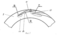
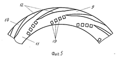
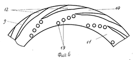
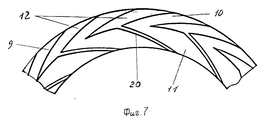
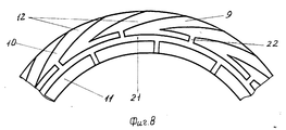
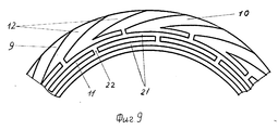
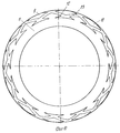
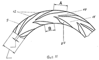
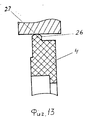
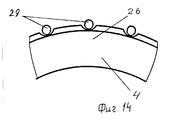
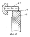
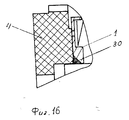
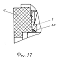
Сущность изобретения поясняется чертежами, где на фиг. 1 представлен продольный разрез уплотнения; на фиг. 2 разрез А-А на фиг. 1; на фиг. 3 - эпюра распределения сил в уплотнительном зазоре при выполнении фаски на внутреннем диаметре уплотнительного элемента; на фиг. 4 эпюра распределения сил в уплотнительном зазоре при выполнении фаски на наружном диаметре уплотнительного элемента; на фиг. 5 конструкция уплотнения со стабилизаторами давления в виде углублений, размещенных на уплотнительной перегородке; на фиг. 6 то же, что и на фиг. 5 (вариант исполнения); на фиг. 7 конструкция уплотнения со стабилизаторами давления в виде наклонных проточных каналов; на фиг. 8 конструкция уплотнения со стабилизаторами давления, связанными между собой кольцевой уравнительной канавкой; на фиг. 9 - конструкция уплотнения со стабилизаторами давления в виде двух уравнительных канавок; на фиг. 10 конструкция уплотнения с реверсивными парами стабилизаторов и концентраторов давления; на фиг. 11 конструкция уплотнения со стабилизаторами давления в виде наклонных каналов, входной частью связанных с полостью низкого давления; на фиг. 12 аксиально-подвижное кольцо с дополнительной центрирующей поверхностью; на фиг. 13 аксиально-подвижное кольцо с дополнительной центрирующей поверхностью в виде части сферы; на фиг. 14 узел стопорения аксиально-подвижного уплотнительного кольца; на фиг. 15 - сечение Б-Б на фиг. 14; на фиг. 16 узел установки вторичного уплотнения со стороны аксиально-подвижного кольца; на фиг. 17 то же, что и на фиг. 16 (вариант исполнения). The invention is illustrated by drawings, where in FIG. 1 is a longitudinal section through a seal; in FIG. 2, section AA in FIG. one; in FIG. 3 is a diagram of the distribution of forces in the sealing gap when performing a chamfer on the inner diameter of the sealing element; in FIG. 4 diagram of the distribution of forces in the sealing gap when performing a chamfer on the outer diameter of the sealing element; in FIG. 5 design of the seal with pressure stabilizers in the form of recesses located on the sealing wall; in FIG. 6 is the same as in FIG. 5 (embodiment); in FIG. 7 seal design with pressure stabilizers in the form of inclined flow channels; in FIG. 8 design of the seal with pressure stabilizers interconnected by an annular equalization groove; in FIG. 9 - seal design with pressure stabilizers in the form of two equalizing grooves; in FIG. 10 seal design with reversible pairs of stabilizers and pressure concentrators; in FIG. 11 design of the seal with pressure stabilizers in the form of inclined channels, the inlet of which is associated with the low-pressure cavity; in FIG. 12 axially movable ring with an additional centering surface; in FIG. 13 axially movable ring with an additional centering surface in the form of part of a sphere; in FIG. 14 locking unit axial-movable sealing ring; in FIG. 15 is a section BB in FIG. 14; in FIG. 16 installation site of the secondary seal on the side of the axially movable ring; in FIG. 17 is the same as in FIG. 16 (option).
Уплотнение вала содержит установленное герметично в корпусе 1 и разделяющее полости высокого 2 и низкого 3 давления аксиально-подвижное уплотнительное кольцо 4 с нажимной пружиной 5 и вторичным уплотнением 6, размещенным в кольцевой проточке 7 корпуса 1 и закрепленное на валу 8 вращающееся уплотнительное кольцо 9, на торцовой поверхности 10 которого выполнены уплотнительная перегородка 11 и расположенные на периферии против направления вращения вала 8 спиральные канавки 12, при этом торцовая поверхность 13 аксиально-подвижного уплотнительного кольца 4 выполнена по крайней мере с фасками 14 на одной из ограничивающих цилиндрических поверхностей 15, а ответная торцовая поверхность 10 вращающегося уплотнительного кольца 9 дополнительно снабжена концентраторами 16 и/или стабилизаторами 17 давления. Концентраторы давления 16 могут быть выполнены в виде выступов 18 размещенных в спиральных канавках 12, выпуклой стороной обращенных к задней стенке канавки 12. Стабилизаторы давления 17 могут быть выполнены в виде углублений 19, расположенных на уплотнительной перегородке 11 вдоль продольных образующих задних стенок спиральных канавок 12. The shaft seal contains an axially
Кроме того, стабилизаторы давления 17 могут быть выполнены в виде наклонных проточных каналов 20, соединяющих донные части спиральных канавок 12 с полостью низкого давления 3, при этом наклонные проточные каналы 20 могут быть связаны между собой кольцевой уравнительной канавкой 21. Стабилизаторы давления 17 могут быть также выполнены в виде по крайней мере двух уравнительных канавок 21, связанных между собой и с донными частями спиральных канавок 12 радиальными перепускными каналами 22. Стабилизаторы 17 и концентраторы 16 давления могут быть также выполнены в виде совмещенных с основными спиральными канавками 12 дополнительных спиральных канавок 23, расположенных на торцовой поверхности 10 вращающегося уплотнительного кольца 9 под равным углом с направлением основных спиральных канавок 12, но направленных в противоположную сторону, причем наружные и донные части основных 12 и дополнительных 23 канавок выполнены с наложением друг на друга. In addition, the pressure stabilizers 17 can be made in the form of
Концентраторы давления 16 могут быть выполнены в виде наклонных каналов 24, входная часть которых расположена со стороны внутренней уплотнительной поверхности вращающегося уплотнительного кольца 9 или полости 3 низкого давления. Аксиально-подвижное уплотнительное кольцо 4 может быть снабжено дополнительным центрирующим пояском 25, выполненным в виде цилиндрического выступа 26 на наружной периферийной поверхности аксиально-подвижного кольца 4. Наружная центрирующая поверхность 27 цилиндрического выступа 26 может быть выполнена в виде части сферы. Цилиндрический выступ 26 может быть снабжены пазами 28 в виде части цилиндра, а в корпусе 1 могут быть установлены штифты 29, диаметр которых меньше диаметра образующих пазов 28. Кольцевая проточка 30 в корпусе 1 под вторичное уплотнение 6 аксиально-подвижного уплотнительного кольца 4 может быть выполнена конической. Кольцевая проточка 30 в корпусе 1 под вторичное уплотнение 6 аксиально-подвижного уплотнительного кольца 4 может также быть выполнена по сфере. Pressure concentrators 16 can be made in the form of
Уплотнение вала работает следующим образом. The shaft seal operates as follows.
При работе турбомашины, например центробежного компрессора высокого давления, перекачиваемый газ, находящийся в полости 2 высокого давления, поступает в спиральные канавки 12, выполненные на торцовой поверхности 10 вращающегося уплотнительного кольца 9. При вращении вала 8 спиральные канавки 12 воздействуют на газовую среду и повышают ее давление, что приводит к созданию уплотнительного слоя газовой среды с большей плотностью, чем ее параметры в полости 3 корпуса 1 под уплотнительными кольцами 4 и 9. Кроме того, компримируемый газ при движении к центру встречает сопротивление донной части спиральные канавок 12, вернее сопротивление уплотнительной перегородки 11. Указанные силовые факторы позволяют установить и поддерживать стабильную величину торцового уплотнительного зазора порядка 3 мкм или близкую к ней на основе равенства гидростатических сил, действующих на наружные поверхности уплотнительных колец 4 и 9, усилия от нажимной пружины 5 и гидродинамической уравновешивающей силы, возникающей за счет воздействия спиральных канавок 12 на газовую среду. Газовая среда при этом разделяет между собой уплотнительные поверхности 10 и 13 колец 4 и 9 и при минимальной утечке исключает их контакт между собой. При изменении режимов эксплуатации возможно изменение величины уплотнительного зазора в сторону его уменьшения или увеличения. В этом случае соответственно изменяются силы в уплотнительное слоем газовой среды. В обоих случаях результатирующая сил остается постоянной или близкой к ней и, таким образом, независимо от условий эксплуатации равновесие сил быстро восстанавливается, восстанавливая тем самым расчетную величину уплотнительного зазора. То есть сравнительно небольшое изменение уплотнительного зазора приводит к появлению значительных неуравновешенных сил, стремящихся вернуть аксиально-подвижное кольцо 4 в первоначальное положение и восстановить первоначальную величину уплотнительного зазора. При этом уплотнение становится нечувствительным к колебаниям давления и другим механическим воздействиям, таким как осевое перемещение, поскольку между уплотнительными кольцами 4 и 5 нет прямого контакта. During operation of a turbomachine, for example, a high-pressure centrifugal compressor, the pumped gas located in the high-pressure cavity 2 enters the
Уплотнение обладает самоцентрирующей способностью, так как при условии отклонения уплотнительного кольца 4 относительно вращающегося кольца 9 на кольцо 4 действует крутящий момент, восстанавливающий параллельность ответных поверхностей 10 и 13 уплотнительных колец 4 и 9. The seal has a self-centering ability, as long as the
В предпочтительном варианте вращающееся уплотнительное кольцо 9 изготовляется из твердых сплавов, например из карбида вольфрама или металлокерамики, т.е. из материала с минимальными деформациями в процессе работы. Аксиально-подвижное кольцо 4 изготовляется из материалов менее стойких, например из силицированного графита. Возможен вариант изготовления пары уплотнительных колец 4 и 9, одно из которых выполнено из карбида кремния, а второе из нитрида кремния. In a preferred embodiment, the rotating
Выполнение спиральных канавок 12 на торцовой поверхности 10 вращающегося уплотнительного кольца 9 может быть осуществлено несколькими способами, например ионным травлением с использованием масок, наносимых на торцовую поверхность 10 вращающегося уплотнительного кольца 9, лазерной обработкой поверхности 10, или спиральные канавки 12 могут быть выполнены механическим путем, например, с использованием традиционных методов металлообработки, в частности фрезерования. The implementation of the
Claims (13)
Applications Claiming Priority (2)
| Application Number | Priority Date | Filing Date | Title |
|---|---|---|---|
| UA95020958A UA21905C2 (en) | 1995-02-28 | 1995-02-28 | Shaft seal |
| UA95020958 | 1995-02-28 |
Publications (2)
| Publication Number | Publication Date |
|---|---|
| RU2080503C1 true RU2080503C1 (en) | 1997-05-27 |
| RU95114134A RU95114134A (en) | 1997-08-10 |
Family
ID=21689045
Family Applications (1)
| Application Number | Title | Priority Date | Filing Date |
|---|---|---|---|
| RU95114134A RU2080503C1 (en) | 1995-02-28 | 1995-08-09 | Shaft stuffing arrangement |
Country Status (2)
| Country | Link |
|---|---|
| RU (1) | RU2080503C1 (en) |
| UA (1) | UA21905C2 (en) |
-
1995
- 1995-02-28 UA UA95020958A patent/UA21905C2/en unknown
- 1995-08-09 RU RU95114134A patent/RU2080503C1/en active
Non-Patent Citations (1)
| Title |
|---|
| 1. Лок К.Р.В., Фон С. Дж. Сухие механические уплотнения для газовых компрессоров и аналогичного оборудования. Техническая информация фирмы "Grane packing Ltd", 1986, с.2-3, рис.1-3. 2. Апанасенко Ф.И., Зиневич Г.Н., Марцинковский В.С., Черепов Л.В., Хорев В.А. Тенденции развития турбокомпрессоров для нефтяной и газовой промышленности. Цинтихимнефтемаш, 1988, обз. информация, "Компрессорное машиностроение". Серия ХМ-5, с.29-33, рис.9. 3. Авторское свидетельство СССР N 1535122, кл. F 16 J 15/34, 1988. * |
Also Published As
| Publication number | Publication date |
|---|---|
| UA21905C2 (en) | 1998-04-30 |
Similar Documents
| Publication | Publication Date | Title |
|---|---|---|
| EP0623768B1 (en) | Labyrinth gas-seal | |
| EP2324209B1 (en) | Intershaft seal system | |
| US6145843A (en) | Hydrodynamic lift seal for use with compressible fluids | |
| US20160097457A1 (en) | Self-pumping hydrodynamic mechanical seal | |
| US2908516A (en) | Circumferential shaft seal | |
| CN1117231C (en) | shaft seal | |
| JPS5936081B2 (en) | Positive displacement fluid device | |
| CA2034460A1 (en) | Thrust force-compensating apparatus with improved hydraulic pressure-responsive balance mechanism | |
| CA2204885A1 (en) | A shaft seal | |
| US5609342A (en) | Gas shaft seal with flexible converging sealing faces | |
| US4554985A (en) | Rotary drill bit | |
| JP2582940B2 (en) | Non-contact packing device for shaft to shut off gas | |
| CN108591473A (en) | Mechanically-sealing apparatus | |
| CA2218516C (en) | A gas seal with locking arrangement | |
| RU2080503C1 (en) | Shaft stuffing arrangement | |
| US5006043A (en) | Floating annular seal with thermal compensation | |
| RU2053371C1 (en) | Turbomachine radial labyrinth seal | |
| SU1760214A1 (en) | Shaft seal | |
| RU2187727C2 (en) | Pulse end seal | |
| EP0629799A1 (en) | Pressure balanced compliant seal device having a flexible annular member | |
| Ettles et al. | The application of double conical journal bearings in high speed centrifugal pumps—parts 1 and 2 | |
| JPS60227011A (en) | Thrust bearing | |
| RU1822914C (en) | Shaft seal | |
| JP7745759B2 (en) | Conical seal assembly for rotary equipment and rotary equipment including the seal assembly - Patents.com | |
| CA2100230C (en) | Simple gas shaft sealing device with flexible rotor |