RU2072523C1 - Inductive distance transducer - Google Patents
Inductive distance transducer Download PDFInfo
- Publication number
- RU2072523C1 RU2072523C1 SU915010469A SU5010469A RU2072523C1 RU 2072523 C1 RU2072523 C1 RU 2072523C1 SU 915010469 A SU915010469 A SU 915010469A SU 5010469 A SU5010469 A SU 5010469A RU 2072523 C1 RU2072523 C1 RU 2072523C1
- Authority
- RU
- Russia
- Prior art keywords
- coil
- period
- output
- sensor according
- input
- Prior art date
Links
Images


Classifications
-
- H—ELECTRICITY
- H03—ELECTRONIC CIRCUITRY
- H03K—PULSE TECHNIQUE
- H03K17/00—Electronic switching or gating, i.e. not by contact-making and –breaking
- H03K17/94—Electronic switching or gating, i.e. not by contact-making and –breaking characterised by the way in which the control signals are generated
- H03K17/945—Proximity switches
- H03K17/95—Proximity switches using a magnetic detector
- H03K17/952—Proximity switches using a magnetic detector using inductive coils
Abstract
Description
Изобретение относится к индуктивным датчикам расстояния, используемым для обнаружения присутствия металлического объекта. The invention relates to inductive distance sensors used to detect the presence of a metal object.
Известны индуктивные датчики расстояния, использующиеся в резонансных схемах. Принцип работы датчика такого типа следующий. В отсутствие металлического объекта вблизи датчика, схема измерения, образованная осциллятором, работающим в резонансе, колеблется со своей максимальной амплитудой. Близость металлического объекта вызывает потери на токи Фуко, наведенные в этом объекте, и вследствие этого затухание резонансной амплитуды. Сравнение этой амплитуды с опорным значением позволяет обнаружить присутствие металлических объектов. Inductive distance sensors are known for use in resonant circuits. The principle of operation of this type of sensor is as follows. In the absence of a metal object near the sensor, the measurement circuit formed by an oscillator operating in resonance oscillates with its maximum amplitude. The proximity of a metal object causes losses due to the Foucault currents induced in this object, and as a result, the attenuation of the resonant amplitude. Comparison of this amplitude with the reference value allows you to detect the presence of metal objects.
Недостатком датчика такого типа является чувствительность к собственным потерям резонансной цепи /омические потери в катушке цепи, потери на гистерезис в магнитной цепи катушки/. Действительно, эти потери зависят от температуры, что является причиной неточности в результатах обнаружения (патент Великобритании 2040054, опублик. 20.08.80). A disadvantage of this type of sensor is its sensitivity to intrinsic losses of the resonant circuit (ohmic losses in the coil of the circuit, losses due to hysteresis in the magnetic circuit of the coil). Indeed, these losses are dependent on temperature, which is the reason for the inaccuracy in the detection results (UK patent 2040054, published. 08.20.80).
Задачей изобретения является устранение указанных недостатков путем предложения усовершенствованного индуктивного датчика расстояния. The objective of the invention is to remedy these disadvantages by proposing an improved inductive distance sensor.
Это достигается тем, что в индуктивном датчике расстояния, содержащем катушку, средства питания катушки, средства измерения и обработки сигналов, обеспечивающие выдачу ответного сигнала в присутствии обнаруживаемой детали, указанные средства питания обеспечивают подачу на катушку периодического тока с периодом Т, причем ток, подаваемый средствами питания на катушку циркулирует в ней в течение времени T1, которое меньше, чем Т, и имеет практически нулевое значение в течение оставшегося промежутка времени (T T1), причем указанные средства измерения и обработки сигналов предназначены для подачи так называемого ответного сигнала на присутствие обнаруживаемой детали в течение оставшейся длительности (T T1) периода.This is achieved by the fact that in an inductive proximity sensor containing a coil, coil power, signal measuring and processing means providing a response signal in the presence of a detectable part, said power means provide a periodic current with a period T to the coil, and the current supplied by the means power to the coil is circulated therein for the time T 1 is less than T, and has a substantially zero value over the remaining period of time (TT 1), said means Measurements and signal processing are used to supply so-called response signal to the detectable presence of the items within the remaining duration (TT 1) period.
На фиг.1 показана принципиальная схема датчика согласно изобретению; на фиг. 2 временная диаграмма напряжений и токов, относящихся к схеме по фиг.1; на фиг. 3 напряжение, наведенное на клеммах катушки по фиг.1; на фиг.4 - пример выполнения датчика согласно изобретению; на фиг.5 временная диаграмма напряжений и токов, относящихся к схеме по фиг.4; на фиг.6 пример выполнения примера по фиг. 4; на фиг.7 второй пример выполнения примера по фиг.4; на фиг.8 временная диаграмму сигналов S4, S5 и SI1 примера выполнения по фиг.7; на фиг.9 пример выполнения средства фильтрации /6/ по фиг.7.Figure 1 shows a schematic diagram of a sensor according to the invention; in FIG. 2 is a timing diagram of voltages and currents related to the circuit of FIG. 1; in FIG. 3 voltage induced on the terminals of the coil of figure 1; figure 4 is an example of a sensor according to the invention; figure 5 is a timing diagram of voltages and currents related to the circuit of figure 4; FIG. 6 is an exemplary embodiment of the example of FIG. 4; in Fig.7, a second exemplary embodiment of the example of Fig.4; Fig.8 is a timing diagram of the signals S 4 , S 5 and SI 1 of the exemplary embodiment of Fig.7; Fig.9 is an example implementation of the filtering means / 6 / Fig.7.
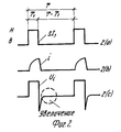
На фиг. 1 принципиальная схема датчика согласно изобретению. Одна из клемм катушки 2 датчика связана с массой питания, а другая с постоянным напряжением U через прерыватель I1, управляемый сигналом SI1.In FIG. 1 is a schematic diagram of a sensor according to the invention. One of the terminals of the
На фиг.2 показана временная диаграмма напряжений и токов, относящихся к схеме по фиг. 1. Сигнал управления ST1 позволяет закрыть прерыватель I1, когда он находится под высоким потенциалом /H/, и открыть I1, когда он находится при низком потенциале /B/. Таким образом, прерыватель I1 управляется периодически с периодом Т, он закрыт в течение времени T1 и открыт в течение времени T T1. Ток i, пересекая катушку 2, устанавливается вследствие этого в соответствии с фиг.2b. Фиг.2с дает напряжение на клеммах катушки 2.FIG. 2 is a timing diagram of voltages and currents related to the circuit of FIG. 1. The control signal ST 1 allows you to close the breaker I 1 when it is at high potential / H /, and open I 1 when it is at a low potential / B /. Thus, the chopper I 1 is controlled periodically with a period T, it is closed during time T 1 and open during time TT 1 . The current i, crossing the
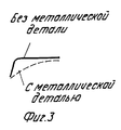
Увеличение этого напряжения в периоде, когда ток равен нулю в катушке, позволяет констатировать, что амплитуда этого напряжения сильно меняется, когда металлическая деталь находится вблизи датчика, это увеличение показано на фиг.3. An increase in this voltage in the period when the current is zero in the coil allows us to state that the amplitude of this voltage varies greatly when the metal part is near the sensor; this increase is shown in Fig. 3.
Это явление объясняется тем, что изменение тока в катушке в течение времени T1 приводит к возникновению токов, наведенных в металлической детали. После принудительного выключения тока в катушке открытием прерывателя I1, наведенные в металлической детали токи продолжают циркулировать создавая напряжение на клеммах катушки. Преимущество этого метода обнаружения состоит в слабой зависимости измеряемого сигнала от температуры. Действительно, напряжение, наведенное в катушке, не зависит от сопротивления последней, а лишь от силы тока, наведенного в металлической детали.This phenomenon is explained by the fact that a change in the current in the coil during the time T 1 leads to the appearance of currents induced in the metal part. After forced shutdown of the current in the coil by opening the breaker I 1 , the currents induced in the metal part continue to circulate, creating voltage at the terminals of the coil. The advantage of this detection method is the low temperature dependence of the measured signal. Indeed, the voltage induced in the coil does not depend on the resistance of the latter, but only on the strength of the current induced in the metal part.
На фиг.4 показан пример выполнения датчика согласно изобретению. Figure 4 shows an example implementation of the sensor according to the invention.
В этом примере выполнения катушка 2 подключена параллельно сопротивлению 4, величина которого приблизительно в 50 раз больше сопротивления катушки. Роль этого сопротивления состоит в подавлении колебаний, обусловленных коммутацией. Вследствие своей большой величины, это сопротивление не оказывает влияния на измерение наведенного напряжения. Прерыватели I2 и I3, управляемые своими сигналами управления SI2 и SI3, позволяют измерять напряжение, наведенное только в течение Т2, когда ток i в катушке практически равен нулю. Наведенное напряжение, обработанное таким образом, подается на усилитель 5. Выходное напряжение усилителя 5 сравнивается с опорным значением, обеспечивая обнаружение присутствия металлической детали.In this exemplary embodiment,
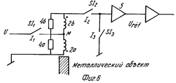
В примере выполнения, показанном на фиг.6, катушка датчика имеет промежуточный выход М, который делит ее на две части 2а и 2b. Сопротивления 4а и 4b играют ту же роль гасителя, что и сопротивление 4 на фиг.4. In the exemplary embodiment shown in FIG. 6, the sensor coil has an intermediate output M, which divides it into two parts 2a and 2b. Resistances 4a and 4b play the same role as a quencher as
Сигналы управления SI1, SI2, SI3 идентичны сигналам, данным на фиг.5.The control signals SI 1 , SI 2 , SI 3 are identical to the signals given in Fig.5.
В течение времени T1 ток циркулирует в участке 2а катушки. Прохождение I1 приводит к возникновению наведенных напряжений в участках катушки 2а и 2в. С учетом направления намотки, эти наведенные напряжения находятся в противофазе. Участок 2b, более удаленный от металлической детали, чем 2а, подает меньшее наведенное напряжение, и, вследствие этого, результирующее наведенное напряжение U1 отлично от нуля.During time T 1, current circulates in the coil portion 2a. The passage of I 1 leads to the appearance of induced voltages in the parts of the coil 2A and 2B. Given the direction of winding, these induced voltages are in antiphase. The portion 2b farther from the metal part than 2a delivers less induced voltage, and, as a result, the resulting induced voltage U 1 is nonzero.
В присутствии возмущающего магнитного поля, частичные напряжения, наведенные в участках 2а и 2b, равны с точностью до знака, подавая, таким образом, результирующее наведенное напряжение U1, практически равное нулю. Этот пример выполнения делает датчик нечувствительным к внешним возмущениям.In the presence of a perturbing magnetic field, the partial voltages induced in sections 2a and 2b are equal to an accuracy of the sign, thereby supplying the resulting induced voltage U 1 substantially equal to zero. This embodiment makes the sensor insensitive to external disturbances.
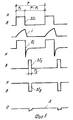
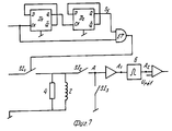
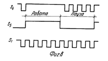
На фиг. 7 показан пример выполнения примера по фиг.4. Сигнал управления SI1 получается сложением сигналов S4 и S5. Сигнал S4 периода T4 подается на синхронизирующий вход СК первого триггера D1, выход Q триггера D1 связан с синхронизирующим входом СК второго триггера D2, выход S5 второго триггера D2 имеет период Т, который в четыре раза больше, чем T4. Сложение сигналов S4 и S5 схемой И выдает сигнал управления SI1 датчика.In FIG. 7 shows an example implementation of the example of figure 4. The control signal SI 1 is obtained by adding signals S 4 and S 5 . A signal S 4 of period T 4 is supplied to the clock input SC of the first trigger D 1 , output Q of trigger D 1 is connected to the clock input SC of the second trigger D 2 , output S 5 of the second trigger D 2 has a period T, which is four times as much as T 4 . The addition of signals S 4 and S 5 circuit And produces a control signal SI 1 sensor.
На фиг.8 показана временная диаграмма сигналов S4, S5 и SI1. Сигнал управления SI1 этого примера выполнения позволяет создать длительность паузы Р и длительность работы S. Длительность паузы обеспечивает двойное преимущество: с одной стороны, она позволяет снизить средний расход датчика, а с другой, оценить постоянную компоненту, вносимую усилителем 5. Для устранения постоянной компоненты, вносимой усилителем 5, выход A1 этого усилителя связан со средством фильтрации 6. Это средство фильтрации может быть просто выполнено с помощью одного конденсатора и одного сопротивления, как это показано на фиг.9.On Fig shows a timing diagram of the signals S 4 , S 5 and SI 1 . The control signal SI 1 of this exemplary embodiment makes it possible to create a pause duration P and an operation duration S. The pause duration provides a double advantage: on the one hand, it reduces the average consumption of the sensor, and on the other hand, it estimates the constant component introduced by
Claims (7)
Applications Claiming Priority (2)
| Application Number | Priority Date | Filing Date | Title |
|---|---|---|---|
| EP90811020.8 | 1990-12-21 | ||
| EP90811020A EP0492029B1 (en) | 1990-12-21 | 1990-12-21 | Inductive proximity sensor |
Publications (1)
| Publication Number | Publication Date |
|---|---|
| RU2072523C1 true RU2072523C1 (en) | 1997-01-27 |
Family
ID=8205980
Family Applications (1)
| Application Number | Title | Priority Date | Filing Date |
|---|---|---|---|
| SU915010469A RU2072523C1 (en) | 1990-12-21 | 1991-12-20 | Inductive distance transducer |
Country Status (8)
| Country | Link |
|---|---|
| EP (1) | EP0492029B1 (en) |
| JP (1) | JP2717743B2 (en) |
| KR (1) | KR970005129B1 (en) |
| AT (1) | ATE82451T1 (en) |
| DE (1) | DE69000465T2 (en) |
| ES (1) | ES2036110T3 (en) |
| GR (1) | GR3006891T3 (en) |
| RU (1) | RU2072523C1 (en) |
Cited By (1)
| Publication number | Priority date | Publication date | Assignee | Title |
|---|---|---|---|---|
| RU2733188C2 (en) * | 2016-04-28 | 2020-09-29 | Коне Корпорейшн | Elevator braking device and method of compensation for change in proximity sensor switching point when temperature changes in braking device |
Families Citing this family (23)
| Publication number | Priority date | Publication date | Assignee | Title |
|---|---|---|---|---|
| EP0936738A1 (en) * | 1998-02-13 | 1999-08-18 | Optosys SA | Inductive proximity switch with one-piece housing |
| EP0936741B1 (en) * | 1998-02-13 | 2009-04-29 | Optosys SA | Inductive proximity switch with a preferably one-piece housing |
| EP0936740B1 (en) * | 1998-02-17 | 2006-06-14 | Optosys SA | Inductive proximity switch |
| EP0936739A1 (en) * | 1998-02-17 | 1999-08-18 | Optosys SA | Inductive proximity switch |
| SE517293C2 (en) * | 1999-06-30 | 2002-05-21 | Abb Ab | Method and apparatus for inductive measurement of geometric dimension and electrical property with opposite magnetic fields |
| CA2312880A1 (en) | 1999-08-25 | 2001-02-25 | The Goodyear Tire & Rubber Company | Rubber composition containing two silicas |
| SG82655A1 (en) * | 1999-11-12 | 2001-08-21 | Aida Eng Ltd | Metal object detecting device |
| DE10041997B4 (en) * | 2000-08-10 | 2005-12-29 | Siemens Ag | Metal-enclosed, gas-insulated switchgear with a device for detecting the gas density |
| US7205166B2 (en) * | 2002-06-28 | 2007-04-17 | Lam Research Corporation | Method and apparatus of arrayed, clustered or coupled eddy current sensor configuration for measuring conductive film properties |
| SE527091C2 (en) * | 2003-12-31 | 2005-12-20 | Abb Ab | Method and apparatus for contactless measurement of thickness and electrical conductivity of a measuring object |
| JP4208206B2 (en) * | 2007-01-02 | 2009-01-14 | 株式会社アヅマシステムズ | Magnetostrictive torque sensor and torque detection method |
| JP2008211762A (en) * | 2007-01-02 | 2008-09-11 | Azuma Systems:Kk | Detecting device and detecting method |
| DE102007001821B4 (en) | 2007-01-12 | 2012-03-01 | Wenglor sensoric elektronische Geräte GmbH | Inductive proximity switch |
| JP4978377B2 (en) * | 2007-08-30 | 2012-07-18 | オムロン株式会社 | Proximity sensor |
| CN102356296B (en) * | 2009-03-17 | 2014-05-07 | Abb公司 | A method and an apparatus for measuring thickness of a metal layer provided on a metal object |
| JP4731636B1 (en) * | 2010-11-26 | 2011-07-27 | 株式会社マコメ研究所 | Magnetic switch |
| DE102011018430B4 (en) | 2011-04-21 | 2019-03-21 | Wenglor Sensoric Gmbh | Inductive proximity switch |
| EP2725715B1 (en) | 2012-10-29 | 2018-12-12 | Optosys SA | Proximity sensor |
| US10516394B2 (en) | 2014-09-09 | 2019-12-24 | Balluff Gmbh | Sensor element of an inductive proximity or distance sensor containing coil arrangement having electrically-conductive shielding with flange completely enclosing the coil arrangement and method for operating the sensor element |
| DE102016115015C5 (en) | 2016-08-12 | 2023-01-26 | Sick Ag | Inductive proximity sensor |
| DE102021000157A1 (en) | 2021-01-15 | 2022-07-21 | Pepperl+Fuchs Se | Inductive proximity sensor unit and method for fault checking in an inductive proximity sensor unit |
| DE102021000156A1 (en) | 2021-01-15 | 2022-07-21 | Pepperl+Fuchs Se | Inductive proximity sensor unit and method for determining an object property of a metallic detection body |
| EP4104661A1 (en) * | 2021-06-17 | 2022-12-21 | CNH Industrial Belgium N.V. | A belt-type cutting system comprising knives for cutting crops, including means for monitoring the condition of the knives |
Family Cites Families (5)
| Publication number | Priority date | Publication date | Assignee | Title |
|---|---|---|---|---|
| US4219740A (en) * | 1979-01-12 | 1980-08-26 | Eldec Corporation | Proximity sensing system and inductance measuring technique |
| JPS5896424A (en) * | 1981-12-03 | 1983-06-08 | Omron Tateisi Electronics Co | Proximity switch |
| EP0231292A1 (en) * | 1985-08-06 | 1987-08-12 | Consolidated Technology Pty. Ltd. | Detector device |
| DE3546245C3 (en) * | 1985-12-28 | 1994-11-17 | Link Walter | Non-contact proximity switch |
| US4845429A (en) * | 1986-03-12 | 1989-07-04 | Eldec Corporation | Inductance divider sensor |
-
1990
- 1990-12-21 AT AT90811020T patent/ATE82451T1/en not_active IP Right Cessation
- 1990-12-21 DE DE9090811020T patent/DE69000465T2/en not_active Expired - Lifetime
- 1990-12-21 ES ES199090811020T patent/ES2036110T3/en not_active Expired - Lifetime
- 1990-12-21 EP EP90811020A patent/EP0492029B1/en not_active Expired - Lifetime
-
1991
- 1991-12-18 JP JP35388491A patent/JP2717743B2/en not_active Expired - Fee Related
- 1991-12-19 KR KR1019910023425A patent/KR970005129B1/en not_active IP Right Cessation
- 1991-12-20 RU SU915010469A patent/RU2072523C1/en active
-
1993
- 1993-01-27 GR GR930400145T patent/GR3006891T3/el unknown
Non-Patent Citations (1)
| Title |
|---|
| Заявка Великобритании N 2040054, G 01R 27/26, 1980 г. * |
Cited By (1)
| Publication number | Priority date | Publication date | Assignee | Title |
|---|---|---|---|---|
| RU2733188C2 (en) * | 2016-04-28 | 2020-09-29 | Коне Корпорейшн | Elevator braking device and method of compensation for change in proximity sensor switching point when temperature changes in braking device |
Also Published As
| Publication number | Publication date |
|---|---|
| JP2717743B2 (en) | 1998-02-25 |
| ES2036110T3 (en) | 1993-05-01 |
| KR920012926A (en) | 1992-07-28 |
| JPH04334115A (en) | 1992-11-20 |
| ATE82451T1 (en) | 1992-11-15 |
| EP0492029B1 (en) | 1992-11-11 |
| KR970005129B1 (en) | 1997-04-12 |
| EP0492029A1 (en) | 1992-07-01 |
| DE69000465D1 (en) | 1992-12-17 |
| GR3006891T3 (en) | 1993-06-30 |
| DE69000465T2 (en) | 1993-05-13 |
Similar Documents
| Publication | Publication Date | Title |
|---|---|---|
| RU2072523C1 (en) | Inductive distance transducer | |
| US4843259A (en) | Process for the non-contacting detection of eddy current-induced bodies, particularly metal objects, as well as to sensors based on the process | |
| US5811965A (en) | DC and AC current sensor having a minor-loop operated current transformer | |
| US5498958A (en) | Inductive proximity sensor with periodic switching for sensing the presence of objects | |
| US4893027A (en) | Proximity switch insensitive to interference fields | |
| JP2923307B2 (en) | Current sensor | |
| JPS5772008A (en) | Position sensor | |
| GB2213594A (en) | Apparatus for measuring the position of the armature of a coil-and-armature magnetic device | |
| US5287059A (en) | Saturable core magnetometer with a parallel resonant circuit in which the W3 DC level changes with a change in an external magnetic field | |
| US5091697A (en) | Low power, high accuracy magnetometer and magnetic field strength measurement method | |
| JP2003121517A (en) | Magnetic detector | |
| ES2132470T3 (en) | MAGNETIC PROXIMITY DETECTOR. | |
| JPS5776451A (en) | Measuring circuit for eddy current magnetic field | |
| JPS568563A (en) | Measuring device for reactance change | |
| KR19990088474A (en) | Device for detecting metallic body | |
| JPH06334507A (en) | High frequency oscillation type proximity sensor | |
| JPS5633521A (en) | Device for measuring stress | |
| JPH05333069A (en) | Method for measuring electric resistance | |
| Vainshtein et al. | Isolation electromagnetically coupled DC and AC current sensor and detector | |
| JPH0810799Y2 (en) | Current sensor | |
| SU1700491A1 (en) | Device for measuring direct current | |
| SU1265586A1 (en) | Probe-type magnetic-field flaw detector | |
| SU1012052A2 (en) | Force measuring device | |
| SU1132269A1 (en) | Magnetometer for measuring low-frequency magnetic fields | |
| SU1062591A1 (en) | Magnetic noise structuroscopy device |