EP0936741B1 - Inductive proximity switch with a preferably one-piece housing - Google Patents
Inductive proximity switch with a preferably one-piece housing Download PDFInfo
- Publication number
- EP0936741B1 EP0936741B1 EP99810022A EP99810022A EP0936741B1 EP 0936741 B1 EP0936741 B1 EP 0936741B1 EP 99810022 A EP99810022 A EP 99810022A EP 99810022 A EP99810022 A EP 99810022A EP 0936741 B1 EP0936741 B1 EP 0936741B1
- Authority
- EP
- European Patent Office
- Prior art keywords
- proximity switch
- coil
- housing
- inductive proximity
- switch according
- Prior art date
- Legal status (The legal status is an assumption and is not a legal conclusion. Google has not performed a legal analysis and makes no representation as to the accuracy of the status listed.)
- Expired - Lifetime
Links
Images
Classifications
-
- H—ELECTRICITY
- H03—ELECTRONIC CIRCUITRY
- H03K—PULSE TECHNIQUE
- H03K17/00—Electronic switching or gating, i.e. not by contact-making and –breaking
- H03K17/94—Electronic switching or gating, i.e. not by contact-making and –breaking characterised by the way in which the control signals are generated
- H03K17/945—Proximity switches
- H03K17/95—Proximity switches using a magnetic detector
- H03K17/9505—Constructional details
-
- H—ELECTRICITY
- H03—ELECTRONIC CIRCUITRY
- H03K—PULSE TECHNIQUE
- H03K17/00—Electronic switching or gating, i.e. not by contact-making and –breaking
- H03K17/94—Electronic switching or gating, i.e. not by contact-making and –breaking characterised by the way in which the control signals are generated
- H03K17/945—Proximity switches
- H03K17/95—Proximity switches using a magnetic detector
- H03K17/952—Proximity switches using a magnetic detector using inductive coils
- H03K17/9525—Proximity switches using a magnetic detector using inductive coils controlled by an oscillatory signal
Definitions
- the invention relates to an inductive proximity switch according to the preamble of claim 1.
- a proximity switch of the type mentioned above is from the EP-A-0492029 known.
- the coil with periodic transmission current pulses of the period T is applied.
- the means for supplying the coil generate a current which is different from zero during a period T1, T1 being less than T, and being kept practically zero during the remaining period of the period, T-T1.
- the receiving voltage is detected with a suitable electronic circuit, which is induced in the coil after the end of a transmission current through the flowing in the body to be detected decaying current flowing there before due to the voltage induced by the transmission current pulse in the coil.
- proximity switch In a further development of the from EP-A-0492029 known proximity switch is the just mentioned, induced in the coil voltage integrated over a relatively short time window, respectively, in order to obtain a smoothed useful signal after suitable processing. This signal is compared with a reference voltage to produce an output signal indicative of the presence of a body to be detected in proximity to the proximity switch, if such a body is located there. With such a proximity switch, an above-average switching distance in the detection of metallic bodies, z. B. made of aluminum or steel.
- the coil arrangement of the sensor consists of at least one generator coil and a detector coil, which are coupled to each other via a ferrite core, and is introduced into a stainless steel housing.
- the generator coil is driven by a triangular generator voltage and, in order to achieve useful switching distances, operated at low frequencies around 100 Hz.
- the proximity switch in the patent US 3,292,052 a proximity switch is described which operates according to the same measuring principle as the sensor according to DE-A1-39 34 593 ,
- the proximity switch includes an exciter coil, two receiver coils and a stainless steel cover provided with mounting brackets.
- the disadvantage is that a relatively thin cover must be selected in order to achieve acceptable switching distances, and therefore offers only minimal protection against mechanical damage.
- the components of known proximity switches which after the in the EP-A-0492029 B1 described principle are working Typically included in a housing consisting of two or more parts, which is usually composed at least of an elongated, metallic cylinder and a cap made of plastic, which closes the active surface 24, ie the exit surface of the magnetic field generated by the coil ,
- a housing consisting of two or more parts, which is usually composed at least of an elongated, metallic cylinder and a cap made of plastic, which closes the active surface 24, ie the exit surface of the magnetic field generated by the coil .
- Such a housing is unsuitable for applications in which the proximity switch is subject to impacts on the plastic cap, particularly aggressive environments or elevated ambient pressure. Such environmental conditions require a very robust housing.
- the invention is therefore based on the object, an inductive proximity switch in the EP-A-0492029 B1 type, which is suitable for use under mechanical stress of the active surface, in aggressive environments and at elevated ambient pressure, but with the still above an average operating distance in the detection of metallic bodies, eg. B. aluminum or steel, can be achieved.
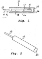
- a proximity switch 11 comprises a coil 12 and an electronic circuit 13.
- This circuit 13 comprises means for feeding the coil with periodic transmission pulses of period T, which is typically chosen between 50 and 500 microseconds, and means for processing signals induced voltages which arise in the coil, when a body to be detected is within the range of influence of the variable magnetic field, which is built up by the coil when it is fed with the periodic transmission current.
- the circuit 13 operates according to the in the in EP-A-0492029 B1 described operation.
- the coil 12 and the circuit 13 are, for example, on a printed circuit board 14 mounted.
- the electronic circuit 13 is connected via lines 15 and 16 of a cable 23 to the device or system (not shown), in which the signals obtained with the proximity switch 11 are further processed.
- Fig. 1 all the components of an inventive proximity switch are arranged in a one-piece housing 21, which, as shown Fig. 2 can be seen, preferably cylindrical.
- the housing 21 may have another suitable shape. It may, for example, have the shape of an elongated cuboid.
- the housing 21 also includes the end 22 of the cylinder on the side of the active surface 24 of the proximity switch.
- This conclusion 22 replaces the cap used in previously known embodiments and has approximately the same wall thickness as such a cap.
- the termination 22 has a wall thickness sufficient to allow good mechanical protection of the coil located behind it.
- the wall thickness of the termination 22 is preferably in a range of 3 to 10% of the outer diameter of the housing 21.
- the wall thickness of the closure 22 is preferably in a range of 3 to 10% of the diameter of a circle which is inscribed in the active area of the proximity switch.
- the housing is made of a metal which is not ferromagnetic and which has a relatively high electrical resistivity, preferably non-magnetic stainless steel. Because of these
- the housing 21 is made entirely of metal and therefore offers the components of the proximity switch 11 a very good protection against aggressive environments.
Description
Die Erfindung betrifft einen induktiven Näherungsschalter gemäss dem Oberbegriff vom Patentanspruch 1.The invention relates to an inductive proximity switch according to the preamble of claim 1.
Ein Näherungsschalter der oben erwähnten Art ist aus der
In einer Weiterentwicklung des aus der
In der Patentanmeldung
In der Patentschrift
Die Komponenten bekannter Näherungsschalter, die nach dem in der
Der Erfindung liegt daher die Aufgabe zugrunde, einen induktiven Näherungsschalter der in der
Diese Aufgabe wird erfindungsgemäss mit einem induktiven Näherungsschalter der in der
Dank seiner Robustheit ist ein solcher Näherungsschalter sogar bei sehr anspruchsvollen Einsatzfällen bei sehr schwierigen-Umgebungsbedingungen verwendbar, wobei die guten Eigenschaften des Näeherungsschalters, insbesondere der damit erzielbare, überdurchschnittlich gute Schaltabstand bei der Erfassung von metallischen Körpern, z. B. aus Aluminium oder Stahl, beibehalten werden.Thanks to its robustness, such a proximity switch can be used even in very demanding applications in very difficult environmental conditions, the good properties of the proximity switch, in particular the achievable, above-average switching distance in the detection of metallic bodies, eg. As aluminum or steel, to be maintained.
Ein Ausführungsbeispiel der Erfindung wird im folgenden anhand der beiliegenden
- Figur 1
- zeigt einen schematischen Querschnitt eines erfindungsgemässen Näherungsschalters,
- Figur 2
- zeigt eine perspektivische Ansicht des Näherungsschalters gemäss
Fig. 1 .
- FIG. 1
- shows a schematic cross section of an inventive proximity switch,
- FIG. 2
- shows a perspective view of the proximity switch according to
Fig. 1 ,
Wie in
Die Spule 12 und die Schaltung 13 sind beispielsweise auf eine gedruckte Leiterplatte 14 montiert. Die elektronische Schaltung 13 ist über Leitungen 15 und 16 eines Kabels 23 mit dem Gerät oder System (nicht gezeigt) verbunden, in dem die mit dem Näherungsschalter 11 gewonnenen Signale weiterverarbeitet werden.The
Wie aus
Das Gehäuse besteht aus einem Metall, welches nicht ferromagnetisch ist und welches einen relativ hohen spezifischen elektrischen Widerstand aufweist, vorzugsweise aus nichtmagnetischem rostfreiem Stahl. Wegen dieserThe housing is made of a metal which is not ferromagnetic and which has a relatively high electrical resistivity, preferably non-magnetic stainless steel. Because of these
Eigenschaften entstehen in der aktiven Fläche 24 während des Betriebs des Näherungsschalters nur sehr kleine Wirbelströme, und die davon in der Spule 12 induzierten Spannungen sind im Messfenster des Nutzsignals vernachlässigbar klein. In zu erfassenden metallischen Körpern aus beispielsweise Stahl oder Aluminium entstehen hingegen wesentlich stärkere Wirbelströme, welche in der Spule Spannungen induzieren, die so stark sind, dass sie die Erfassung solcher Körper mit einem überdurchschnittlich grossen Schaltabstand ermöglichen.Characteristics arise in the
Das Gehäuse 21 besteht vollständig aus Metall und bietet daher den Komponenten des Näherungsschalters 11 einen sehr guten Schutz gegen aggressive Umgebungen.The
Claims (6)
- Inductive proximity switch comprising- a coil,- means for supplying the coil with periodic transmitting current pulses,- means for processing signals that correspond to voltages induced in the coil after the end of a transmitting current pulse by the decaying current previously flowing in the body that is to be detected due to the voltage induced therein by the transmitting current pulse,
which proximity switch
is characterised in that
the coil (12), the means for supplying the coil with periodic transmitting current pulses, and the means for processing signals are arranged in a housing (21) that is closed on the side of the active surface (24) of the proximity switch and consists of a metal that is not ferromagnetic and has a relatively high specific electric resistance. - Inductive proximity switch according to claim 1, characterised in that the housing (21) is made of one piece.
- Inductive proximity switch according to one of claims 1 or 2, characterised in that the housing (21) is made of non-magnetic stainless steel.
- Inductive proximity switch according to one of the preceding claims, characterised in that the period of the transmitting current pulses lies between 50 and 500 microseconds.
- Inductive proximity switch according to one of the preceding claims, characterised in that the housing (21) is cylindrical and has a closure (22) whose wall thickness lies in a range of 3 to 10 % of the outer diameter of the housing (21).
- Inductive proximity switch according to one of the preceding claims, characterised in that the housing (21) has a closure (22) whose wall thickness is in a range of 3 to 10 % of the diameter of a circle inscribed into the active surface of the proximity switch.
Priority Applications (1)
| Application Number | Priority Date | Filing Date | Title |
|---|---|---|---|
| EP99810022A EP0936741B1 (en) | 1998-02-13 | 1999-01-14 | Inductive proximity switch with a preferably one-piece housing |
Applications Claiming Priority (3)
| Application Number | Priority Date | Filing Date | Title |
|---|---|---|---|
| EP98810116 | 1998-02-13 | ||
| EP19980810116 EP0936738A1 (en) | 1998-02-13 | 1998-02-13 | Inductive proximity switch with one-piece housing |
| EP99810022A EP0936741B1 (en) | 1998-02-13 | 1999-01-14 | Inductive proximity switch with a preferably one-piece housing |
Publications (2)
| Publication Number | Publication Date |
|---|---|
| EP0936741A1 EP0936741A1 (en) | 1999-08-18 |
| EP0936741B1 true EP0936741B1 (en) | 2009-04-29 |
Family
ID=26151869
Family Applications (1)
| Application Number | Title | Priority Date | Filing Date |
|---|---|---|---|
| EP99810022A Expired - Lifetime EP0936741B1 (en) | 1998-02-13 | 1999-01-14 | Inductive proximity switch with a preferably one-piece housing |
Country Status (1)
| Country | Link |
|---|---|
| EP (1) | EP0936741B1 (en) |
Cited By (1)
| Publication number | Priority date | Publication date | Assignee | Title |
|---|---|---|---|---|
| US20140091786A1 (en) * | 2012-09-04 | 2014-04-03 | Peter Heimlicher | Method of manufacturing an inductive proximity switch |
Families Citing this family (5)
| Publication number | Priority date | Publication date | Assignee | Title |
|---|---|---|---|---|
| DE102007001821B4 (en) | 2007-01-12 | 2012-03-01 | Wenglor sensoric elektronische Geräte GmbH | Inductive proximity switch |
| DE102009049821A1 (en) | 2009-10-19 | 2011-04-21 | Icontrols, K.S. | Apparatus and method for detecting electrically conductive objects |
| EP2429077B1 (en) * | 2010-09-14 | 2013-04-10 | Optosys SA | Inductive proximity switch |
| EP2511736B1 (en) | 2011-04-15 | 2016-02-17 | iControls, k.s. | Method and device for detecting objects which conduct electricity |
| EP2725715B1 (en) * | 2012-10-29 | 2018-12-12 | Optosys SA | Proximity sensor |
Citations (3)
| Publication number | Priority date | Publication date | Assignee | Title |
|---|---|---|---|---|
| US3292052A (en) * | 1963-09-19 | 1966-12-13 | Cutler Hammer Inc | Proximity switching system |
| US4906926A (en) * | 1988-05-16 | 1990-03-06 | Syron Engineering & Manufacturing Corporation | Proximity sensor for hostile environments |
| DE4102542A1 (en) * | 1991-01-29 | 1992-07-30 | Turck Werner Kg | Inductive proximity switch with constant trigger distance - has oscillator producing magnetic field influenced by difference between field sensing coil voltages |
Family Cites Families (3)
| Publication number | Priority date | Publication date | Assignee | Title |
|---|---|---|---|---|
| DE3934593A1 (en) * | 1989-10-17 | 1991-04-25 | Hiss Eckart | Security sensor for contactless metal detection - has generator prim. coils coupled to sec. detector coils, pref. via ferrite core |
| ATE82451T1 (en) * | 1990-12-21 | 1992-11-15 | Detra Sa | INDUCTIVE PROXIMITY SENSOR. |
| DE19516934C1 (en) * | 1995-05-09 | 1996-08-29 | Pepperl & Fuchs | Inductive proximity switch with oscillator coil |
-
1999
- 1999-01-14 EP EP99810022A patent/EP0936741B1/en not_active Expired - Lifetime
Patent Citations (3)
| Publication number | Priority date | Publication date | Assignee | Title |
|---|---|---|---|---|
| US3292052A (en) * | 1963-09-19 | 1966-12-13 | Cutler Hammer Inc | Proximity switching system |
| US4906926A (en) * | 1988-05-16 | 1990-03-06 | Syron Engineering & Manufacturing Corporation | Proximity sensor for hostile environments |
| DE4102542A1 (en) * | 1991-01-29 | 1992-07-30 | Turck Werner Kg | Inductive proximity switch with constant trigger distance - has oscillator producing magnetic field influenced by difference between field sensing coil voltages |
Cited By (1)
| Publication number | Priority date | Publication date | Assignee | Title |
|---|---|---|---|---|
| US20140091786A1 (en) * | 2012-09-04 | 2014-04-03 | Peter Heimlicher | Method of manufacturing an inductive proximity switch |
Also Published As
| Publication number | Publication date |
|---|---|
| EP0936741A1 (en) | 1999-08-18 |
Similar Documents
| Publication | Publication Date | Title |
|---|---|---|
| DE2912712C2 (en) | ||
| DE602004010486T2 (en) | Inductive proximity sensor | |
| EP0936738A1 (en) | Inductive proximity switch with one-piece housing | |
| DE19831372C2 (en) | Device for checking non-positive connections | |
| DE10014348B4 (en) | Device for nondestructive measurement of the thickness of thin layers | |
| DE19736454A1 (en) | Contactless proximity switch | |
| EP0218042A2 (en) | Magnetic-field-dependent electronic proximity switch | |
| DE102009058549A1 (en) | Detection device for a belt conveyor and method for detecting electrically conductive foreign bodies in the conveyed a belt conveyor | |
| DE102016115015C5 (en) | Inductive proximity sensor | |
| EP1360525B1 (en) | Locating device | |
| EP0936741B1 (en) | Inductive proximity switch with a preferably one-piece housing | |
| EP0060392A2 (en) | Coin testing apparatus | |
| DE10057773B4 (en) | proximity switch | |
| EP1526645B1 (en) | Inductive proximity switch with differential coils | |
| DE10234960B4 (en) | Sensor according to the transit time principle with a detector unit for mechanical-elastic waves | |
| DE3544264C2 (en) | ||
| EP2876308B1 (en) | Cylinder-piston unit with evaluation unit for determining the position of the piston | |
| DE4325406B4 (en) | proximity switch | |
| EP0351700A2 (en) | Arrangement for the capacitive fluid level measurement | |
| DE102007001821B4 (en) | Inductive proximity switch | |
| DE3244507A1 (en) | Magnetic-field-dependent inductive proximity switch | |
| CH689460A5 (en) | Piston-cylinder device with inductive stroke-measuring sensor for stroke controlled lifting of loads | |
| EP0494617A2 (en) | Device for non-contact indentification of objects | |
| DE69911745T2 (en) | INDUCTION SENSOR | |
| DE10064507B4 (en) | Magnetic field sensitive proximity sensor |
Legal Events
| Date | Code | Title | Description |
|---|---|---|---|
| PUAI | Public reference made under article 153(3) epc to a published international application that has entered the european phase |
Free format text: ORIGINAL CODE: 0009012 |
|
| AK | Designated contracting states |
Kind code of ref document: A1 Designated state(s): AT BE CH DE ES FR GB IT LI NL SE |
|
| AX | Request for extension of the european patent |
Free format text: AL;LT;LV;MK;RO;SI |
|
| 17P | Request for examination filed |
Effective date: 19991115 |
|
| AKX | Designation fees paid |
Free format text: AT BE CH DE ES FR GB IT LI NL SE |
|
| 17Q | First examination report despatched |
Effective date: 20020725 |
|
| APBN | Date of receipt of notice of appeal recorded |
Free format text: ORIGINAL CODE: EPIDOSNNOA2E |
|
| APBR | Date of receipt of statement of grounds of appeal recorded |
Free format text: ORIGINAL CODE: EPIDOSNNOA3E |
|
| APAA | Appeal reference recorded |
Free format text: ORIGINAL CODE: EPIDOS REFN |
|
| APAF | Appeal reference modified |
Free format text: ORIGINAL CODE: EPIDOSCREFNE |
|
| APBT | Appeal procedure closed |
Free format text: ORIGINAL CODE: EPIDOSNNOA9E |
|
| GRAP | Despatch of communication of intention to grant a patent |
Free format text: ORIGINAL CODE: EPIDOSNIGR1 |
|
| GRAS | Grant fee paid |
Free format text: ORIGINAL CODE: EPIDOSNIGR3 |
|
| RTI1 | Title (correction) |
Free format text: INDUCTIVE PROXIMITY SWITCH WITH A PREFERABLY ONE-PIECE HOUSING |
|
| GRAA | (expected) grant |
Free format text: ORIGINAL CODE: 0009210 |
|
| AK | Designated contracting states |
Kind code of ref document: B1 Designated state(s): AT BE CH DE ES FR GB IT LI NL SE |
|
| REG | Reference to a national code |
Ref country code: GB Ref legal event code: FG4D Free format text: NOT ENGLISH |
|
| REG | Reference to a national code |
Ref country code: CH Ref legal event code: NV Representative=s name: AMMANN PATENTANWAELTE AG BERN Ref country code: CH Ref legal event code: EP |
|
| REF | Corresponds to: |
Ref document number: 59915012 Country of ref document: DE Date of ref document: 20090610 Kind code of ref document: P |
|
| NLV1 | Nl: lapsed or annulled due to failure to fulfill the requirements of art. 29p and 29m of the patents act | ||
| PG25 | Lapsed in a contracting state [announced via postgrant information from national office to epo] |
Ref country code: ES Free format text: LAPSE BECAUSE OF FAILURE TO SUBMIT A TRANSLATION OF THE DESCRIPTION OR TO PAY THE FEE WITHIN THE PRESCRIBED TIME-LIMIT Effective date: 20090809 |
|
| PG25 | Lapsed in a contracting state [announced via postgrant information from national office to epo] |
Ref country code: SE Free format text: LAPSE BECAUSE OF FAILURE TO SUBMIT A TRANSLATION OF THE DESCRIPTION OR TO PAY THE FEE WITHIN THE PRESCRIBED TIME-LIMIT Effective date: 20090729 Ref country code: NL Free format text: LAPSE BECAUSE OF FAILURE TO SUBMIT A TRANSLATION OF THE DESCRIPTION OR TO PAY THE FEE WITHIN THE PRESCRIBED TIME-LIMIT Effective date: 20090429 |
|
| PLBI | Opposition filed |
Free format text: ORIGINAL CODE: 0009260 |
|
| 26 | Opposition filed |
Opponent name: EGE ELECTRONIC GMBH Effective date: 20100116 |
|
| PLAX | Notice of opposition and request to file observation + time limit sent |
Free format text: ORIGINAL CODE: EPIDOSNOBS2 |
|
| PLAF | Information modified related to communication of a notice of opposition and request to file observations + time limit |
Free format text: ORIGINAL CODE: EPIDOSCOBS2 |
|
| BERE | Be: lapsed |
Owner name: OPTOSYS SA Effective date: 20100131 |
|
| PLBB | Reply of patent proprietor to notice(s) of opposition received |
Free format text: ORIGINAL CODE: EPIDOSNOBS3 |
|
| PG25 | Lapsed in a contracting state [announced via postgrant information from national office to epo] |
Ref country code: BE Free format text: LAPSE BECAUSE OF NON-PAYMENT OF DUE FEES Effective date: 20100131 |
|
| PG25 | Lapsed in a contracting state [announced via postgrant information from national office to epo] |
Ref country code: AT Free format text: LAPSE BECAUSE OF NON-PAYMENT OF DUE FEES Effective date: 20100114 |
|
| PLBD | Termination of opposition procedure: decision despatched |
Free format text: ORIGINAL CODE: EPIDOSNOPC1 |
|
| PLBP | Opposition withdrawn |
Free format text: ORIGINAL CODE: 0009264 |
|
| PLBM | Termination of opposition procedure: date of legal effect published |
Free format text: ORIGINAL CODE: 0009276 |
|
| STAA | Information on the status of an ep patent application or granted ep patent |
Free format text: STATUS: OPPOSITION PROCEDURE CLOSED |
|
| 27C | Opposition proceedings terminated |
Effective date: 20130208 |
|
| REG | Reference to a national code |
Ref country code: FR Ref legal event code: PLFP Year of fee payment: 18 |
|
| REG | Reference to a national code |
Ref country code: FR Ref legal event code: PLFP Year of fee payment: 19 |
|
| REG | Reference to a national code |
Ref country code: FR Ref legal event code: PLFP Year of fee payment: 20 |
|
| PGFP | Annual fee paid to national office [announced via postgrant information from national office to epo] |
Ref country code: DE Payment date: 20180122 Year of fee payment: 20 Ref country code: CH Payment date: 20180123 Year of fee payment: 20 Ref country code: GB Payment date: 20180119 Year of fee payment: 20 |
|
| PGFP | Annual fee paid to national office [announced via postgrant information from national office to epo] |
Ref country code: FR Payment date: 20180119 Year of fee payment: 20 Ref country code: IT Payment date: 20180129 Year of fee payment: 20 |
|
| REG | Reference to a national code |
Ref country code: DE Ref legal event code: R071 Ref document number: 59915012 Country of ref document: DE |
|
| REG | Reference to a national code |
Ref country code: CH Ref legal event code: PL |
|
| REG | Reference to a national code |
Ref country code: GB Ref legal event code: PE20 Expiry date: 20190113 |
|
| PG25 | Lapsed in a contracting state [announced via postgrant information from national office to epo] |
Ref country code: GB Free format text: LAPSE BECAUSE OF EXPIRATION OF PROTECTION Effective date: 20190113 |