RU2071017C1 - Evaporation heat exchange apparatus - Google Patents
Evaporation heat exchange apparatus Download PDFInfo
- Publication number
- RU2071017C1 RU2071017C1 SU925052600A SU5052600A RU2071017C1 RU 2071017 C1 RU2071017 C1 RU 2071017C1 SU 925052600 A SU925052600 A SU 925052600A SU 5052600 A SU5052600 A SU 5052600A RU 2071017 C1 RU2071017 C1 RU 2071017C1
- Authority
- RU
- Russia
- Prior art keywords
- housing
- tubes
- medium
- space
- evaporated
- Prior art date
Links
Images

Classifications
-
- F—MECHANICAL ENGINEERING; LIGHTING; HEATING; WEAPONS; BLASTING
- F28—HEAT EXCHANGE IN GENERAL
- F28F—DETAILS OF HEAT-EXCHANGE AND HEAT-TRANSFER APPARATUS, OF GENERAL APPLICATION
- F28F9/00—Casings; Header boxes; Auxiliary supports for elements; Auxiliary members within casings
- F28F9/22—Arrangements for directing heat-exchange media into successive compartments, e.g. arrangements of guide plates
-
- B—PERFORMING OPERATIONS; TRANSPORTING
- B01—PHYSICAL OR CHEMICAL PROCESSES OR APPARATUS IN GENERAL
- B01D—SEPARATION
- B01D1/00—Evaporating
- B01D1/04—Evaporators with horizontal tubes
-
- B—PERFORMING OPERATIONS; TRANSPORTING
- B64—AIRCRAFT; AVIATION; COSMONAUTICS
- B64G—COSMONAUTICS; VEHICLES OR EQUIPMENT THEREFOR
- B64G1/00—Cosmonautic vehicles
- B64G1/22—Parts of, or equipment specially adapted for fitting in or to, cosmonautic vehicles
- B64G1/46—Arrangements or adaptations of devices for control of environment or living conditions
- B64G1/50—Arrangements or adaptations of devices for control of environment or living conditions for temperature control
-
- F—MECHANICAL ENGINEERING; LIGHTING; HEATING; WEAPONS; BLASTING
- F28—HEAT EXCHANGE IN GENERAL
- F28D—HEAT-EXCHANGE APPARATUS, NOT PROVIDED FOR IN ANOTHER SUBCLASS, IN WHICH THE HEAT-EXCHANGE MEDIA DO NOT COME INTO DIRECT CONTACT
- F28D5/00—Heat-exchange apparatus having stationary conduit assemblies for one heat-exchange medium only, the media being in contact with different sides of the conduit wall, using the cooling effect of natural or forced evaporation
-
- F—MECHANICAL ENGINEERING; LIGHTING; HEATING; WEAPONS; BLASTING
- F28—HEAT EXCHANGE IN GENERAL
- F28F—DETAILS OF HEAT-EXCHANGE AND HEAT-TRANSFER APPARATUS, OF GENERAL APPLICATION
- F28F19/00—Preventing the formation of deposits or corrosion, e.g. by using filters or scrapers
- F28F19/006—Preventing deposits of ice
-
- F—MECHANICAL ENGINEERING; LIGHTING; HEATING; WEAPONS; BLASTING
- F28—HEAT EXCHANGE IN GENERAL
- F28F—DETAILS OF HEAT-EXCHANGE AND HEAT-TRANSFER APPARATUS, OF GENERAL APPLICATION
- F28F27/00—Control arrangements or safety devices specially adapted for heat-exchange or heat-transfer apparatus
- F28F27/02—Control arrangements or safety devices specially adapted for heat-exchange or heat-transfer apparatus for controlling the distribution of heat-exchange media between different channels
-
- F—MECHANICAL ENGINEERING; LIGHTING; HEATING; WEAPONS; BLASTING
- F28—HEAT EXCHANGE IN GENERAL
- F28D—HEAT-EXCHANGE APPARATUS, NOT PROVIDED FOR IN ANOTHER SUBCLASS, IN WHICH THE HEAT-EXCHANGE MEDIA DO NOT COME INTO DIRECT CONTACT
- F28D21/00—Heat-exchange apparatus not covered by any of the groups F28D1/00 - F28D20/00
- F28D2021/0019—Other heat exchangers for particular applications; Heat exchange systems not otherwise provided for
- F28D2021/0021—Other heat exchangers for particular applications; Heat exchange systems not otherwise provided for for aircrafts or cosmonautics
-
- F—MECHANICAL ENGINEERING; LIGHTING; HEATING; WEAPONS; BLASTING
- F28—HEAT EXCHANGE IN GENERAL
- F28D—HEAT-EXCHANGE APPARATUS, NOT PROVIDED FOR IN ANOTHER SUBCLASS, IN WHICH THE HEAT-EXCHANGE MEDIA DO NOT COME INTO DIRECT CONTACT
- F28D21/00—Heat-exchange apparatus not covered by any of the groups F28D1/00 - F28D20/00
- F28D2021/0019—Other heat exchangers for particular applications; Heat exchange systems not otherwise provided for
- F28D2021/0061—Other heat exchangers for particular applications; Heat exchange systems not otherwise provided for for phase-change applications
- F28D2021/0064—Vaporizers, e.g. evaporators
-
- F—MECHANICAL ENGINEERING; LIGHTING; HEATING; WEAPONS; BLASTING
- F28—HEAT EXCHANGE IN GENERAL
- F28D—HEAT-EXCHANGE APPARATUS, NOT PROVIDED FOR IN ANOTHER SUBCLASS, IN WHICH THE HEAT-EXCHANGE MEDIA DO NOT COME INTO DIRECT CONTACT
- F28D21/00—Heat-exchange apparatus not covered by any of the groups F28D1/00 - F28D20/00
- F28D2021/0019—Other heat exchangers for particular applications; Heat exchange systems not otherwise provided for
- F28D2021/0068—Other heat exchangers for particular applications; Heat exchange systems not otherwise provided for for refrigerant cycles
- F28D2021/0071—Evaporators
-
- F—MECHANICAL ENGINEERING; LIGHTING; HEATING; WEAPONS; BLASTING
- F28—HEAT EXCHANGE IN GENERAL
- F28F—DETAILS OF HEAT-EXCHANGE AND HEAT-TRANSFER APPARATUS, OF GENERAL APPLICATION
- F28F9/00—Casings; Header boxes; Auxiliary supports for elements; Auxiliary members within casings
- F28F9/22—Arrangements for directing heat-exchange media into successive compartments, e.g. arrangements of guide plates
- F28F2009/222—Particular guide plates, baffles or deflectors, e.g. having particular orientation relative to an elongated casing or conduit
- F28F2009/226—Transversal partitions
-
- F—MECHANICAL ENGINEERING; LIGHTING; HEATING; WEAPONS; BLASTING
- F28—HEAT EXCHANGE IN GENERAL
- F28F—DETAILS OF HEAT-EXCHANGE AND HEAT-TRANSFER APPARATUS, OF GENERAL APPLICATION
- F28F2255/00—Heat exchanger elements made of materials having special features or resulting from particular manufacturing processes
- F28F2255/04—Heat exchanger elements made of materials having special features or resulting from particular manufacturing processes comprising shape memory alloys or bimetallic elements
Landscapes
- Engineering & Computer Science (AREA)
- Physics & Mathematics (AREA)
- Thermal Sciences (AREA)
- Mechanical Engineering (AREA)
- General Engineering & Computer Science (AREA)
- Life Sciences & Earth Sciences (AREA)
- Chemical Kinetics & Catalysis (AREA)
- Health & Medical Sciences (AREA)
- Chemical & Material Sciences (AREA)
- Biodiversity & Conservation Biology (AREA)
- Environmental & Geological Engineering (AREA)
- Environmental Sciences (AREA)
- General Health & Medical Sciences (AREA)
- Toxicology (AREA)
- Remote Sensing (AREA)
- Aviation & Aerospace Engineering (AREA)
- Heat-Exchange Devices With Radiators And Conduit Assemblies (AREA)
Abstract
Description
Изобретение касается испарительного теплообменного аппарата в соответствии с ограничительной частью пункта I формулы изобретения. The invention relates to an evaporative heat exchanger in accordance with the restrictive part of paragraph I of the claims.
У космических летательных аппаратов, которые находятся в стадии подъема или спуска через атмосферу земли или которые на околоземной орбите подвержены экстремальным термическим нагрузкам, необходимо наверняка и надежно отводить образующееся тепло. Для этой цели среди прочего используются испарительные теплообменные аппараты. For spacecraft that are in the process of ascending or descending through the atmosphere of the earth or which are subject to extreme thermal loads in near-earth orbit, the generated heat must surely and reliably be removed. For this purpose, among other things, evaporative heat exchangers are used.
Основополагающим принципом подобного рода теплообменных аппаратов является то, что охлаждаемая среда активного жидкостного циркуляционного контура для отвода тепла приводится в теплопередающий контакт с испаряемой средой, которая хранится в имеющемся резервуаре и которая затем в виде пара отводится от космического летательного аппарата в окружающую среду. The fundamental principle of this kind of heat exchangers is that the cooled medium of the active liquid circulation circuit for heat removal is brought into heat transfer contact with the vaporized medium, which is stored in an existing tank and which is then removed in the form of steam from the spacecraft into the environment.
Чтобы оптимально использовать испаряемую среду путем по возможности полного испарения, важным является то, чтобы обеспечить по возможности хороший термический контакт и тем самым по возможности полный переход тепла между охлаждающей жидкостью с одной стороны и испаряемой средой с другой стороны. In order to optimally utilize the evaporated medium by means of complete evaporation, it is important to ensure as good thermal contact as possible and thereby the complete heat transfer between the coolant on the one hand and the evaporated medium on the other.
В известном классе подобного рода теплообменных аппаратов, который описан, например, в патенте ФРГ N 3718873, охлаждающая жидкость протекает по отдельным каналам через технологическое пространство, в которое через впускной клапан каплями впрыскивается испаряемая среда. Во втором классе испарительных теплообменных аппаратов, к которому также можно отнести изобретение, охлаждающая жидкость напротив протекает открыто через технологическое пространство, в то время как испаряемая среда направляется через это пространство по отдельным, расположенным, как правило, в виде секций каналам. При этом охлаждающая жидкость дополнительно с помощью расположенных в технологическом пространстве заслонок принудительно направляется в виде меандрового потока. In a well-known class of heat exchangers of this kind, which is described, for example, in the German Federal Patent No. 3718873, the coolant flows through separate channels through the technological space into which the vaporized medium is injected with droplets through the inlet valve. In the second class of evaporative heat exchangers, to which the invention can also be attributed, the cooling liquid, on the contrary, flows openly through the technological space, while the evaporated medium is directed through this space through separate channels, usually located in sections. At the same time, the coolant is additionally forcibly sent in the form of a meander flow using dampers located in the technological space.
В подобного рода испарительном теплообменном аппарате, если в нем в качестве охлаждающей жидкости используется вода, существует опасность оледенения. Чтобы предотвратить эту опасность, при известных обстоятельствах может быть необходимым воздействовать на температуру испарения испаряемой среды, в качестве которой часто используется аммиак. In this kind of evaporative heat exchanger, if water is used as a coolant in it, there is a risk of glaciation. In order to prevent this danger, under certain circumstances it may be necessary to affect the evaporation temperature of the vaporized medium, which is often used ammonia.
Задачей изобретения является выполнение испарительного теплообменного аппарата в соответствии с родовым понятием таким образом, чтобы он предоставлял простую и одновременно надежную с точки зрения функционирования возможность для регулирования температуры испарения испаряемой среды. The objective of the invention is the implementation of the evaporative heat exchanger in accordance with the generic concept so that it provides a simple and at the same time reliable from the point of view of functioning, the ability to control the temperature of evaporation of the evaporated medium.
Изобретение решает эту задачу с помощью теплообменного аппарата с отличительными признаками пункта I формулы изобретения. При этом в соответствии с изобретением на давление испарившейся среды влияют путем изменения поперечного сечения выпускного отверстия и таким образом одновременно влияют на температуру испарения таким образом, что опасность оледенения надежно исключена. Особенно простым способом это происходит благодаря тому, что поток пара разделяется на несколько частных потоков, которые соответственно направляются с помощью отдельных выпускных заслонок. Путем целенаправленного открывания или закрывания отдельных этих заслонок можно тогда простым способом влиять на давление испарения. При этом в другом варианте выполнения изобретения открывание или закрывание может осуществляться с помощью нагруженного температурой впуска охлаждающей жидкости регулирующего устройства, в простейшем случае с помощью биметаллической пружины. (Это, в частности, возможно тогда, когда поток пара разделяется на основной поток, заслонка которого постоянно остается открытой, а также, по меньшей мере, на три дополнительных паровых потока. Даже если в случае неисправности в подобного рода системе одна из дополнительных заслонок остается закрытой, температура испарения лишь незначительно возрастает выше заданной величины и наоборот. В обоих случаях система остается полностью работоспособной. The invention solves this problem using a heat exchanger with the hallmarks of paragraph I of the claims. Moreover, in accordance with the invention, the pressure of the evaporated medium is influenced by changing the cross section of the outlet and thus simultaneously affect the evaporation temperature so that the risk of glaciation is reliably eliminated. In a particularly simple way, this is due to the fact that the steam stream is divided into several private streams, which are respectively guided using separate exhaust dampers. By targeted opening or closing of these individual dampers, the evaporation pressure can then be influenced in a simple way. Moreover, in another embodiment of the invention, the opening or closing can be carried out using a temperature-loaded coolant inlet of the regulating device, in the simplest case using a bimetallic spring. (This, in particular, is possible when the steam stream is divided into the main stream, the valve of which is constantly open, as well as at least three additional steam flows. Even if in the event of a malfunction in such a system one of the additional valves remains closed, the evaporation temperature only slightly increases above a predetermined value and vice versa.In both cases, the system remains fully operational.
Сущность изобретения поясняется ниже, чертежами, на которых показано:
фиг.1 продольный разрез первого испарительного теплообменного аппарата;
фиг.2 вид сбоку системы в соответствии с фиг.1;
фиг.3 вид системы в соответствии с фиг.1 сверху;
фиг. 4-6 вертикальные разрезы различных зон изображенной на фиг.1 системы,
фиг.7 принципиальный эскиз второго испарительного теплообменного аппарата;
фиг.8 разрез теплообменного аппарата в соответствии с фиг.7;
фиг.9 разрез зоны выпуска изображенного на фиг.7 теплообменного аппарата и
фиг.10 разрез частичной зоны показанной на фиг.7 системы.The invention is illustrated below, by drawings, which show:
figure 1 is a longitudinal section of a first evaporative heat exchanger;
figure 2 side view of the system in accordance with figure 1;
figure 3 view of the system in accordance with figure 1 from above;
FIG. 4-6 vertical sections of various zones depicted in figure 1 of the system,
7 is a schematic sketch of a second evaporative heat exchanger;
Fig.8 is a section of a heat exchanger in accordance with Fig.7;
Fig.9 is a section of the exhaust zone depicted in Fig.7 heat exchanger and
figure 10 section of a partial zone shown in Fig.7 system.
На чертеже одинаковые конструктивные элементы обозначены одинаковыми условными обозначениями. In the drawing, the same structural elements are denoted by the same conventions.
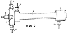
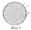
Изображенный на фиг.1 испарительный теплообменный аппарат состоит из цилиндрического корпуса 1, в котором в технологическом пространстве 2 расположена секция однотипных трубочек 3, которые проходят параллельно продольной оси корпуса и которые, как в частности, показывает изображение поперечного разреза на фиг.4, равномерно распределены по всему поперечному сечению технологического пространства. При этом удаление отдельных трубочек 3 друг от друга выбрано, по меньшей мере, равным удалению, которое имеет воображаемая кромка секции трубочек от внутренней стенки корпуса 1. Корпус 1 имеет соответственно на концах присоединительный фланец 4 или 5, с помощью которых корпус 1 соединен с двумя концевыми телами 6 и 7, конструкция которых ниже поясняется более подробно. The evaporative heat exchanger shown in FIG. 1 consists of a cylindrical body 1, in which a section of tubes of the
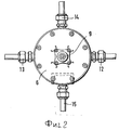
Левое на фиг.1 концевое тело 6 имеет центральное впускное пространство 8 для испаряемой среды, в случае описанного здесь примера выполнения изобретения аммиака (NH3), которое сужается в направлении к впускному клапану 9 конусообразно. Размер радиуса открытого к технологическому пространству 2 впускного пространства 8 выбран таким образом, что это пространство охватывает внутреннюю группу трубочек 3, причем их количество составляет примерно 50 процентов от общего количества имеющихся трубочек 3. Эти трубочки выступают через пластину с отверстиями 10, которая образует непосредственный запор технологического пространства 2, внутрь впускного пространства 8. Остальные 50 процентов трубочек секции, которые образуют внешнее кольцо этой секции, также выступают через пластину с отверстиями 10 в кольцевое пространство 11, которое окружает впускное пространство 8 и которое оснащено в целом четырьмя входными отверстиями 12-15 для испарившейся среды, расположенными со смещением относительно друг друга на 10o.The
При этом два из этих выходных отверстий 12-15, которые скрыты в изображении на фиг.1, можно видеть на фиг.3. На этом изображении, повернутом относительно изображения в соответствии с фиг.1 на 90o, можно видеть кроме того выход 16, а также вход 17, которые предусмотрены для охлаждающей жидкости, в данном случае воды, и которые соединены непосредственно с технологическим пространством 2. В то время как выход 16 расположен в зоне увеличенного диаметра корпуса 1, вход 17 находится в частичной цилиндрической зоне правого на чертеже концевого тела 7.In this case, two of these outlet openings 12-15, which are hidden in the image in figure 1, can be seen in figure 3. In this image, rotated relative to the image in accordance with FIG. 1 by 90 ° , one can also see the
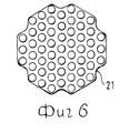
Через это, названное последним концевое тело 7, как видно из фиг.1, содержащие испаряемую среду трубочки 3 проведены до сборного пространства 18, которое ограничивает внутреннюю полость концевого тела 7 и через которое группа внутренних трубочек 3, которые соединены с впускным пространством 8, соединена с группой расположенных снаружи трубочек 3. Наконец, соответственно, попеременно, внутри технологического пространства 2 расположены два различных вида отклоняющих заслонок. В случае с этими отклоняющими заслонками речь идет, во-первых, о заслонках 19 с отверстиями, как они представлены на фиг.5, и при которых в середине технологического пространства 2 остается отверстие 20. Во-вторых, речь идет о кольцевых заслонках 21, которые освобождают отверстие в форме кольцевого зазора в технологическом пространстве 2. Наконец, вся система смонтирована на несущем элементе 22. Through this, called the
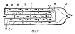
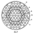
Принцип действия описанной выше системы необходимо пояснить с помощью второго примера выполнения изобретения, который прежде всего представлен с помощью упрощенного принципиального эскиза на фиг.7. На этом принципиальном эскизе по соображениям наглядности отказались от изображения имеющегося между отдельными, направляющими испаряемую среду трубочками 33 технологического пространства. Как видно из изображения поперечного сечения этого теплообменного аппарата на фиг.8, в этом случае расположенные внутри корпуса 31 в технологическом пространстве 32 трубочки 33 объединены в целом в три группы: центральную группу 34, состоящую примерно из 20-30 трубочек, расположенных в центре секции, промежуточную группу 35 примерно с таким же количеством трубочек, а также краевую группу, состоящую примерно из 30-40 трубочек. The principle of operation of the system described above needs to be explained with the help of a second embodiment of the invention, which is primarily represented by a simplified conceptual sketch in Fig. 7. On this principle sketch, for reasons of clarity, they abandoned the image of the technological space available between the individual tubes guiding the evaporated
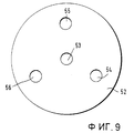
На обоих концах технологического пространства 32 эти группы трубочек соединены друг с другом с помощью сборных пространств, а именно, группы 34 и 35 с помощью центрального сборного пространства 37, а группы 35 и 36, на стороне впуска испаряемой среды, с помощью кольцевого сборного пространства 38, которое окружает впускное отверстие 39 для подачи испаряемой среды. Наконец, испарившаяся среда собирается в выпускном пространстве. Последнее закрыто с помощью изображенной на фиг.9 пластины 52, в которой расположено несколько заслонок с отверстиями 52-56. Из этих заслонок заслонка 53, расположенная в центре, является неизменяемой, в то время как заслонки 54-56 соответственно могут закрываться с помощью механизма, который изображен на фиг. 10. At both ends of the
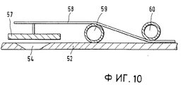
Этот механизм состоит из крышки 57, которая удерживается на биметаллической пружине 58, которая в свою очередь вставлена между двумя трубочками 59 и 60. Последние относятся к петле, через которую протекает часть охлаждающей жидкости, поступающей в технологическое пространство 32. This mechanism consists of a
В этом испарительном теплообменном аппарате также в попеременной последовательности предусмотрены отклоняющие заслонки 49 и 51. Впускное и выпускное отверстия для протекающей через технологическое пространство охлаждающей жидкости в этом изображении опущены. Направления движения жидкости, в данном случае вновь воды, и испаряемой среды, аммиака, соответственно обозначены стрелками. In this evaporative heat exchanger, deflecting
Охлаждающая жидкость поступает в правую на чертеже часть технологического пространства с входной температурой, которая в случае описанного здесь примера выполнения находится в пределах примерно от 24 до 67oС. Затем охлаждающая жидкость протекает между трубочками с испаряемой средой, причем она большей частью передает содержащееся в ней тепло этой среде, прежде чем она не будет выходить из технологического пространства с температурой примерно 5-6oС. При этом расположенные попеременно в технологическом пространстве отклоняющиеся заслонки, как видно из фиг.6, способствует созданию меандрового потока охлаждающей жидкости, что приводит к постоянно новому перемешиванию и тем самым к очень гомогенному распределению температуры протекающих между трубочками потоков охлаждающей жидкости.The coolant enters the right-hand part of the technological space with an inlet temperature, which, in the case of the exemplary embodiment described here, is in the range of about 24 to 67 ° C. Then, the coolant flows between the tubes with the evaporated medium, and for the most part it transfers contained in it heat this medium before it will not come out from the treatment space at a temperature of about 5-6 o C. in this case arranged alternately in the process space deviating barrier and as seen from Figure 6, contributes to meander the cooling fluid flow, which leads to a new constant agitation and thus to a very homogeneous temperature distribution occurring between the coolant flow tubes.
На другой стороне в центральную группу трубочек подается испаряемая среда с входной температурой около -10oС. При протекании по трубочкам она нагревается до температуры испарения и возможно уже начинается испарение. На конце трубочек она попадает в общее для всех трубочек центральные группы, по которым она протекает, сборное пространство, которое находится на выпускном конце, откуда она отклоняется и направляется в трубочки промежуточной группы. При этом в результате отклонения на 180o она перемешивается.On the other side, a vaporized medium with an inlet temperature of about -10 ° C is supplied to the central group of tubes. When it flows through the tubes, it heats up to the evaporation temperature and evaporation may already begin. At the end of the ducts, it falls into the central for all ducts central groups along which it flows, the collection space, which is located at the outlet end, from where it deviates and goes into the ducts of the intermediate group. Moreover, as a result of a deviation of 180 o it is mixed.
Тем самым во всех центральных трубочках преобладают одинаковые условия протекания. Теперь аммиак протекает в том же направлении, что и охлаждающая жидкость, со стороны выпуска аммиака к стороне подачи аммиака, и при этом почти полностью испаряется. При этом, так как конец центральных трубочек расположен на стороне выхода воды теплообменного аппарата, испаряемая среда перегревается максимум до температуры выхода (6oС). Она протекает во второе сборное пространство, где при новом отклонении на 180o вновь создаются почти гомогенные условия протекания для следующего участка протекания аммиака.Thus, the same flow conditions prevail in all central ducts. Ammonia now flows in the same direction as the coolant, from the ammonia discharge side to the ammonia supply side, and almost completely evaporates. Moreover, since the end of the central tubes is located on the water outlet side of the heat exchanger, the evaporated medium overheats to a maximum temperature at the outlet temperature (6 ° C). It flows into the second collection space, where with a new 180 ° deviation, almost homogeneous flow conditions are again created for the next ammonia flow section.
Наконец, аммиак, нагруженный небольшим количеством оставшихся капель, вновь протекает против направления потока воды по краевым трубочкам к сторону поступления воды и выпуска аммиака теплообменного аппарата. При этом она нагревается до разности остаточной температуры: примерно от 5 до 10oС относительно температуры воды на выходе, которая в зависимости от нагрузки находится в пределах 24-67oС и затем поступает в ограниченное пластиной 52 выпускное пространство 40. Путем открывания и закрывания одной или нескольких заслонок 54-56 теперь можно регулировать давление испарения таким образом, что исключается опасность оледенения для охлаждающей жидкости. При этом изменение открывания заслонок осуществляется в зависимости от температуры охлаждающей жидкости на выходе, так что в любое время обеспечено оптимальное рабочее состояние.Finally, ammonia, loaded with a small amount of the remaining droplets, again flows against the direction of the flow of water along the edge tubes towards the water inlet and the ammonia outlet of the heat exchanger. At the same time, it heats up to the difference in the residual temperature: from about 5 to 10 o С relative to the outlet water temperature, which, depending on the load, is in the range of 24-67 o С and then enters the
Claims (6)
Applications Claiming Priority (2)
| Application Number | Priority Date | Filing Date | Title |
|---|---|---|---|
| DEP4130693.7 | 1991-09-14 | ||
| DE4130693A DE4130693C1 (en) | 1991-09-14 | 1991-09-14 |
Publications (1)
| Publication Number | Publication Date |
|---|---|
| RU2071017C1 true RU2071017C1 (en) | 1996-12-27 |
Family
ID=6440671
Family Applications (1)
| Application Number | Title | Priority Date | Filing Date |
|---|---|---|---|
| SU925052600A RU2071017C1 (en) | 1991-09-14 | 1992-09-11 | Evaporation heat exchange apparatus |
Country Status (5)
| Country | Link |
|---|---|
| US (1) | US5253701A (en) |
| EP (1) | EP0532849B1 (en) |
| JP (1) | JP2651089B2 (en) |
| DE (1) | DE4130693C1 (en) |
| RU (1) | RU2071017C1 (en) |
Families Citing this family (7)
| Publication number | Priority date | Publication date | Assignee | Title |
|---|---|---|---|---|
| DE4243316C2 (en) * | 1992-12-21 | 1996-04-18 | Daimler Benz Aerospace Ag | Oil coolers for space vehicles |
| GB9303355D0 (en) * | 1993-02-19 | 1993-04-07 | Yorkshire Process Plant | Method and apparatus for the treatment of sugar confectionary |
| DE10157714A1 (en) * | 2001-11-24 | 2003-06-26 | Daimler Chrysler Ag | Method and devices for carrying out the method for influencing the operating temperature of a hydraulic operating means for a drive unit of a vehicle |
| DE10333463C5 (en) * | 2003-07-22 | 2014-04-24 | Alstom Technology Ltd. | Tube heat exchanger |
| ATE472080T1 (en) * | 2004-04-23 | 2010-07-15 | Aarhuskarlshamn Denmark As | SYSTEM AND HEAT EXCHANGER FOR INCREASING THE TEMPERATURE OF A SUBSTANCE THAT INITIALLY OCCURS IN AN AT LEAST PARTIALLY SOLID STATE IN A CONTAINER |
| EP2496902B1 (en) * | 2009-11-04 | 2014-05-07 | Evapco, INC. | Hybrid heat exchange apparatus |
| US8678753B2 (en) * | 2009-11-30 | 2014-03-25 | Rolls-Royce Corporation | Passive flow control through turbine engine |
Family Cites Families (8)
| Publication number | Priority date | Publication date | Assignee | Title |
|---|---|---|---|---|
| US2867990A (en) * | 1956-01-24 | 1959-01-13 | Garrett Corp | Spray type evaporative cooler |
| GB1129404A (en) * | 1966-03-17 | 1968-10-02 | Vauxhall Motors Ltd | Radiators for motor vehicle engines |
| JPS5992391U (en) * | 1982-12-11 | 1984-06-22 | 大生工業株式会社 | Heat exchange medium control device |
| JPS59189290A (en) * | 1983-03-28 | 1984-10-26 | チユ−イ インダストリ−ズ インコ−ポレ−テツド | Heat exchanger |
| DE3419442A1 (en) * | 1983-05-25 | 1984-12-20 | Kogata Gasu Reibo-gijutsu Kenkyu Kumiai, Tokio/Tokyo | HEAT EXCHANGER |
| DE3718873C1 (en) * | 1987-06-05 | 1988-11-10 | Erno Raumfahrttechnik Gmbh | Evaporative cooler |
| JP2592869B2 (en) * | 1987-11-17 | 1997-03-19 | 宇宙開発事業団 | Heat exchange equipment |
| JPH0633966B2 (en) * | 1988-08-12 | 1994-05-02 | 動力炉・核燃料開発事業団 | Flow control mechanism of heat exchanger |
-
1991
- 1991-09-14 DE DE4130693A patent/DE4130693C1/de not_active Expired - Lifetime
-
1992
- 1992-07-08 EP EP92111539A patent/EP0532849B1/en not_active Expired - Lifetime
- 1992-09-04 US US07/940,471 patent/US5253701A/en not_active Expired - Fee Related
- 1992-09-11 RU SU925052600A patent/RU2071017C1/en not_active IP Right Cessation
- 1992-09-11 JP JP4243769A patent/JP2651089B2/en not_active Expired - Fee Related
Non-Patent Citations (1)
| Title |
|---|
| Патент Великобритании N 1604571, кл. F 25 B 39/02, 1978. * |
Also Published As
| Publication number | Publication date |
|---|---|
| EP0532849B1 (en) | 1995-06-28 |
| DE4130693C1 (en) | 1992-10-29 |
| EP0532849A2 (en) | 1993-03-24 |
| EP0532849A3 (en) | 1993-04-21 |
| JPH05203376A (en) | 1993-08-10 |
| JP2651089B2 (en) | 1997-09-10 |
| US5253701A (en) | 1993-10-19 |
Similar Documents
| Publication | Publication Date | Title |
|---|---|---|
| RU2071017C1 (en) | Evaporation heat exchange apparatus | |
| US10386130B2 (en) | Flow devices and methods for guiding fluid flow | |
| US5419391A (en) | Steam generator with axial flow preheater | |
| DE2820734A1 (en) | WASTE STORAGE | |
| CN106979100A (en) | Heat-exchange device | |
| CN101014804A (en) | Heat accumulating gas processing system | |
| US10249397B2 (en) | Modular reactor steam generator configured to cover a reactor outer wall circumference | |
| US4106559A (en) | Tube side flow control device for moisture separator reheaters | |
| US10249393B2 (en) | Modular reactor steam generator configured to cover a reactor outer wall circumference | |
| US4494484A (en) | Heat exchanger for a process gas | |
| ITTO970622A1 (en) | AIR CONDITIONING EQUIPMENT OF THE ABSORPTION TYPE WITH NERATORS AND FINNED PIPE LINES OF THE ABSORPTION LIQUID. | |
| US3939805A (en) | Steam generator | |
| JP2643062B2 (en) | Vaporization heat exchanger | |
| US6736329B2 (en) | Heating unit for heat-transfer fluid for a central heating installation | |
| US3863711A (en) | Method and apparatus for maintaining substantial uniformity in the temperature of a heat-exchanging fluid | |
| KR20000076283A (en) | Liquid distributor, falling film heat exchanger and absorption refrigerator | |
| KR200491936Y1 (en) | Dehumidification system | |
| CN214700730U (en) | Air preheater for incinerator | |
| EP0033575A2 (en) | Multi-stage expansion evaporator | |
| KR19990023667A (en) | Heat exchanger system for boiler with circulating fluidized bed | |
| GB2060156A (en) | A heat exchange fluid-cooling system and apparatus | |
| SU1211508A1 (en) | Spray attemperator of steam turbine exhaust part | |
| KR101082470B1 (en) | Heat exchanger | |
| KR101082471B1 (en) | Heat exchanger | |
| RU2265171C2 (en) | Regulated heat exchanger |
Legal Events
| Date | Code | Title | Description |
|---|---|---|---|
| MM4A | The patent is invalid due to non-payment of fees |
Effective date: 20040912 |