RU2058905C1 - Linear drive for safety belt system - Google Patents
Linear drive for safety belt system Download PDFInfo
- Publication number
- RU2058905C1 RU2058905C1 RU9393004576A RU93004576A RU2058905C1 RU 2058905 C1 RU2058905 C1 RU 2058905C1 RU 9393004576 A RU9393004576 A RU 9393004576A RU 93004576 A RU93004576 A RU 93004576A RU 2058905 C1 RU2058905 C1 RU 2058905C1
- Authority
- RU
- Russia
- Prior art keywords
- piston
- damping device
- drive according
- gas generator
- traction cable
- Prior art date
Links
Images

Classifications
-
- B—PERFORMING OPERATIONS; TRANSPORTING
- B60—VEHICLES IN GENERAL
- B60R—VEHICLES, VEHICLE FITTINGS, OR VEHICLE PARTS, NOT OTHERWISE PROVIDED FOR
- B60R22/00—Safety belts or body harnesses in vehicles
- B60R22/34—Belt retractors, e.g. reels
- B60R22/46—Reels with means to tension the belt in an emergency by forced winding up
- B60R22/4619—Transmission of tensioning power by cable, e.g. using a clutch on reel side
-
- B—PERFORMING OPERATIONS; TRANSPORTING
- B60—VEHICLES IN GENERAL
- B60R—VEHICLES, VEHICLE FITTINGS, OR VEHICLE PARTS, NOT OTHERWISE PROVIDED FOR
- B60R22/00—Safety belts or body harnesses in vehicles
- B60R22/28—Safety belts or body harnesses in vehicles incorporating energy-absorbing devices
-
- F—MECHANICAL ENGINEERING; LIGHTING; HEATING; WEAPONS; BLASTING
- F16—ENGINEERING ELEMENTS AND UNITS; GENERAL MEASURES FOR PRODUCING AND MAINTAINING EFFECTIVE FUNCTIONING OF MACHINES OR INSTALLATIONS; THERMAL INSULATION IN GENERAL
- F16C—SHAFTS; FLEXIBLE SHAFTS; ELEMENTS OR CRANKSHAFT MECHANISMS; ROTARY BODIES OTHER THAN GEARING ELEMENTS; BEARINGS
- F16C2240/00—Specified values or numerical ranges of parameters; Relations between them
- F16C2240/12—Force, load, stress, pressure
-
- Y—GENERAL TAGGING OF NEW TECHNOLOGICAL DEVELOPMENTS; GENERAL TAGGING OF CROSS-SECTIONAL TECHNOLOGIES SPANNING OVER SEVERAL SECTIONS OF THE IPC; TECHNICAL SUBJECTS COVERED BY FORMER USPC CROSS-REFERENCE ART COLLECTIONS [XRACs] AND DIGESTS
- Y10—TECHNICAL SUBJECTS COVERED BY FORMER USPC
- Y10T—TECHNICAL SUBJECTS COVERED BY FORMER US CLASSIFICATION
- Y10T74/00—Machine element or mechanism
- Y10T74/20—Control lever and linkage systems
- Y10T74/20396—Hand operated
- Y10T74/20402—Flexible transmitter [e.g., Bowden cable]
- Y10T74/2045—Flexible transmitter [e.g., Bowden cable] and sheath support, connector, or anchor
-
- Y—GENERAL TAGGING OF NEW TECHNOLOGICAL DEVELOPMENTS; GENERAL TAGGING OF CROSS-SECTIONAL TECHNOLOGIES SPANNING OVER SEVERAL SECTIONS OF THE IPC; TECHNICAL SUBJECTS COVERED BY FORMER USPC CROSS-REFERENCE ART COLLECTIONS [XRACs] AND DIGESTS
- Y10—TECHNICAL SUBJECTS COVERED BY FORMER USPC
- Y10T—TECHNICAL SUBJECTS COVERED BY FORMER US CLASSIFICATION
- Y10T74/00—Machine element or mechanism
- Y10T74/20—Control lever and linkage systems
- Y10T74/20396—Hand operated
- Y10T74/20402—Flexible transmitter [e.g., Bowden cable]
- Y10T74/20462—Specific cable connector or guide
Abstract
Description
Изобретение относится к линейному приводу для удерживающих систем транспортных средств с пиротехническим газогенератором и активируемым за счет газов, производимых этим газогенератором, блоком поршень-цилиндр, к поршню которого присоединен тяговый тросик. Такой линейный привод требуется в особенности в устройствах натяжения ремня, расположенных на устройстве для намотки ремня или в другом месте ременной системы. The invention relates to a linear drive for holding systems of vehicles with a pyrotechnic gas generator and activated by the gases produced by this gas generator, a piston-cylinder unit, to the piston of which a traction cable is connected. Such a linear drive is required in particular in belt tensioning devices located on the belt winding device or elsewhere in the belt system.
Доказана эффективность устройства натяжения ремня в различных конструктивных формах. Последние исследования показали, что защитное действие ремня безопасности может быть дополнительно усилено в том случае, когда натяжение осуществляется с усилием, повышенным по сравнению с обычными устройствами натяжения ремня. Мощность устройства натяжения ремня может быть усилена за счет того, что пиротехническому газогенератору задаются большие размеры. Тогда помимо линейного привода самого по себе должны выполняться с большими размерами также тяговый тросик и механизм, через который передается повышенное усилие на ленту ремня, для того, чтобы выдерживались возникающие нагрузки. The effectiveness of the belt tensioning device in various structural forms is proved. Recent studies have shown that the protective effect of the seat belt can be further enhanced when the tension is applied with a force that is higher than conventional belt tension devices. The power of the belt tensioning device can be enhanced due to the fact that the pyrotechnic gas generator is given large dimensions. Then, in addition to the linear drive, the pull cable and the mechanism through which increased force is transmitted to the belt belt must also be carried out with large dimensions in order to withstand the arising loads.
В основе изобретения лежит знание того, что повышение мощности устройства натяжения может достигаться без повышения или, по меньшей мере, без существенного повышения мощности газогенератора за счет того, что освобожденная этим газогенератором энергия используется лучшим образом. Согласно изобретению поршень и тяговый тросик соединены друг с другом через демпфирующее устройство, которое ограничивает усилие, производимое поршнем на тяговом тросике в фазе роста давления газов, производимых газогенератором и позволяет постоянное, преимущественно в виде прогрессии увеличение этого усилия. The basis of the invention is the knowledge that an increase in the power of the tensioning device can be achieved without increasing or at least without significantly increasing the power of the gas generator due to the fact that the energy released by this gas generator is used in the best way. According to the invention, the piston and the traction cable are connected to each other through a damping device, which limits the force exerted by the piston on the traction cable in the phase of pressure increase of the gases produced by the gas generator and allows a constant increase, mainly in the form of progression, of this force.
В соответствии с обычным представлением о принципе действия блока поршень-цилиндр с пиротехническим газогенератором достижимая механическая мощность в первую очередь определяется действующим на поршень осевым усилием, производимым за счет нагружения торцевой поверхности поршня давлением газа. При этом исходят из того представления, что это усилие имеется в распоряжении на всем участке пути поршня в цилиндре. In accordance with the usual concept of the principle of operation of a piston-cylinder unit with a pyrotechnic gas generator, the achievable mechanical power is primarily determined by the axial force acting on the piston produced by loading the end surface of the piston with gas pressure. At the same time, it is assumed that this force is available over the entire portion of the piston path in the cylinder.
В основе изобретения лежит знание того, что эта предпосылка не соответствует действительности. Давление газа, производимое имеющимся в распоряжении газогенератором, после зажигания газогенератора сначала резко возрастает и уже через 1 мс или менее достигается максимальная величина. Вслед за тем давление вновь падает и приблизительно через 3 мс после зажигания имеет величину, меньшую, чем приблизительно 10% от его максимальной величины. Следовательно, намного большая часть освобожденной газогенератором энергии имеется в распоряжении в течение лишь небольшой части того времени, которое требуется поршню для полного хода, составляющего, например, 200 мм. За счет мероприятия согласно изобретению, в соответствии с которым поршень и тяговый тросик соединены друг с другом через демпфирующее устройство, освобожденная газогенератором энергия оптимальным образом преобразуется в ускорение поршня. В частности, достигается то, что максимум ускорения поршня, по меньшей мере, приблизительно совпадает с максимумом кривой давления газа на временной оси. Следовательно, демпфирование является эффективным в течение всей начальной фазы движения поршня, в которой возрастает давление газа, произведенное газогенератором. В этой начальной фазе поршень проходит сравнительно малый отрезок пути, составляющий приблизительно от 5 до 15% от всего хода поршня. При ходе поршня 200 мм поршень в этой начальной фазе проходит, например, отрезок пути, составляющий приблизительно лишь 16 мм. В основе изобретения лежит, далее, знание того, что необходимо найти путь к тому, чтобы освобожденная газогенератором энергия, которая имеется в распоряжении при общепотребительских осуществлениях в течение лишь приблизительно 2-3 мс, аккумулировалась так, чтобы необходимое для натяжения ремня усилие оставалось в распоряжении в течение всего хода устройства натяжения ремня. Было найдено, что это аккумулирование может осуществляться лишь механическим путем. При использовании устройства натяжения ремня, расположенного на устройстве для намотки ремня и через соединительный механизм воздействующего на ременную катушку эта ременная катушка с намотанной на нее лентой ремня может рассматриваться, как аккумулятор энергии. Следовательно, ременная катушка должна ускоряться в пределах от 1 до 2 мс до такого числа оборотов, чтобы в примыкающей фазе, в которой давление газа почти исчезло, момента инерции ременной катушки и намотанной на нее ленты ремня было достаточно для того, чтобы в течение всего хода устройства натяжения ремня обеспечивалось необходимое усилие. Воздействующий на ременную катушку вращающий момент после зажигания газогенератора может нарастать круто, но не слишком резко. Благодаря демпфирующему устройству может устанавливаться оптимальное изменение вращающего момента, воздействующего на ременную катушку. Особенно благоприятным является тот случай, когда усилие, передаваемое от поршня на тяговый тросик с помощью демпфирующего устройства в фазе нарастания давления прогрессивно возрастает вместе с пройденным отрезком пути. The invention is based on the knowledge that this premise is not true. The gas pressure produced by the gas generator available after ignition of the gas generator first rises sharply and after 1 ms or less the maximum value is reached. Subsequently, the pressure drops again and approximately 3 ms after ignition has a value less than approximately 10% of its maximum value. Therefore, a much larger part of the energy released by the gas generator is available for only a small part of the time that the piston needs for a full stroke, for example, 200 mm. Due to the measure according to the invention, in accordance with which the piston and the traction cable are connected to each other through a damping device, the energy released by the gas generator is optimally converted into acceleration of the piston. In particular, it is achieved that the maximum acceleration of the piston at least approximately coincides with the maximum of the gas pressure curve on the time axis. Therefore, damping is effective during the entire initial phase of the movement of the piston, in which the gas pressure produced by the gas generator increases. In this initial phase, the piston travels a relatively small length of the path, comprising approximately 5 to 15% of the total piston stroke. When the piston stroke is 200 mm, the piston in this initial phase passes, for example, a distance of approximately 16 mm. The invention is further based on the knowledge that it is necessary to find a way to ensure that the energy liberated by the gas generator, which is available in consumer applications for only about 2-3 ms, is accumulated so that the force necessary for tensioning the belt remains during the entire course of the belt tensioner. It was found that this accumulation can only be carried out mechanically. When using a belt tensioning device located on a belt winding device and through a connecting mechanism acting on a belt reel, this belt reel with a belt tape wound thereon can be considered as an energy accumulator. Therefore, the belt reel should be accelerated in the range from 1 to 2 ms to such a speed that in the adjacent phase, in which the gas pressure has almost disappeared, the moment of inertia of the belt reel and the belt tape wound around it is sufficient to ensure that throughout the course belt tensioning devices provided the necessary force. The torque acting on the belt coil after ignition of the gas generator can increase steeply, but not too sharply. Thanks to the damping device, an optimum change in the torque acting on the belt coil can be established. Especially favorable is the case when the force transmitted from the piston to the traction cable with the help of a damping device in the phase of increasing pressure progressively increases with the distance traveled.
Известен линейный привод, имеющий поршень, к которому присоединена тяга с устройством ограничения усилия для действующего при натяжении ремня усиления. Ограничение усилия, желаемое в этом линейном приводе, достигается за счет того, что при превышении заранее заданного предельного усилия открывается разгрузочный клапан после преодоления усилия пружины сжатия. Эта пружина сжатия имеет также размеры, что в нормальной рабочей фазе линейного привода разгрузочный клапан остается закрытым. Однако, согласно изобретению по сравнению с этим возрастающее при процессе натяжения усилие не ограничивается, а в возможно большей степени полностью используется имеющаяся в распоряжении энергия и преобразуется в механическое усилие приводное, что неожиданным образом достигается с помощью демпфирующего устройства [1]
В зависимости от осуществления газогенератора и состава его пиротехнического заряда промежуток времени, в течение которого имеется в распоряжении давление газа, также может быть несколько большим, чем 2-3 мс, и падение кривой давления газа происходит менее круто. В таких случаях давление газа также во время промежуточной фазы и конечной фазы движения поршня вносит свой вклад в приводную мощность. Однако, в принципе, также при таких осуществлениях намного большая часть энергии освобождается непосредственно после зажигания в течение 2-3 мс, так что вслед за тем должна получаться большая часть приводной мощности механической энергии, аккумулируемая при вращательном движении ременной катушкой и находящейся на ней лентой ремня.A linear actuator having a piston is known, to which a rod is connected with a force limiting device for the reinforcement belt acting when tensioning. The force limitation desired in this linear actuator is achieved by the fact that when the predetermined ultimate force is exceeded, the relief valve opens after overcoming the force of the compression spring. This compression spring also has dimensions that in the normal operating phase of the linear actuator, the discharge valve remains closed. However, according to the invention, in comparison with this, the force increasing during the tensioning process is not limited, but, to the greatest extent possible, the available energy is fully used and converted into a mechanical driving force, which is unexpectedly achieved using a damping device [1]
Depending on the implementation of the gas generator and the composition of its pyrotechnic charge, the period of time during which the gas pressure is available can also be somewhat longer than 2-3 ms, and the gas pressure curve decreases less steeply. In such cases, the gas pressure also during the intermediate phase and the final phase of the piston movement contributes to the drive power. However, in principle, also in such implementations, a much larger part of the energy is released immediately after ignition for 2-3 ms, so that after that a large part of the drive power of mechanical energy should be obtained, which is accumulated during the rotational movement of the belt coil and the belt tape located on it .
В качестве демпфирующего устройства в принципе рассматриваются два осуществления: согласно первому осуществлению демпфирующее устройство представляет собой упруго податливую деталь, вставленную на пути передачи усилия между поршнем и тяговым тросиком, согласно второму осуществлению демпфирующее устройство образовано с помощью пластически деформируемой детали, также вставленной на пути передачи усилия между поршнем и тяговым тросиком. Различные формы осуществления демпфирующего устройства приведены в дополнительных пунктах формулы изобретения. In principle, two embodiments are considered as a damping device: according to the first embodiment, the damping device is an elastically pliable part inserted in the force transmission path between the piston and the pull cable, according to the second embodiment, the damping device is formed using a plastically deformable part also inserted in the force transmission path between the piston and the pull cable. Various forms of implementation of the damping device are given in additional claims.
Дальнейшие признаки и преимущества изобретения вытекают из описания и из чертежей, на которые делается ссылка. Further features and advantages of the invention arise from the description and from the referenced drawings.
На фиг. 1 дана диаграмма, показывающая изменение давления газа, ускорение поршня и путь поршня в зависимости от времени; на фиг. 2 схематическое изображение пиротехнического линейного привода для устройства натяжения ремня, воздействующего на устройство для намотки ремня; на фиг. 3 диаграмма, показывающая желательное изменение действующего в тяговом тросике усилия в зависимости от отрезка пути в начальной фазе движения поршня; на фиг. 4 вид в разрезе первой формы осуществления линейного привода, снабженного согласно изобретению, демпфирующим устройством между поршнем и тяговым тросиком; на фиг. 5 соответственно, продольный разрез блока поршень-цилиндр с демпфирующим устройством согласно второму варианту его осуществления до действия нагрузки; на фиг. 6 то же, что на фиг. 5 после деформации демпфирующего устройства; на фиг. 7 вид в разрезе аналогично по третьему варианту выполнения демпфирующего устройства; на фиг. 8 то же, что на фиг. 7 после деформации демпфирующего устройства; на фиг. 9 продольный разрез следующей формы осуществления, при котором блок поршень-цилиндр одновременно образует преобразователь энергии; на фиг. 10 поперечный разрез фиг. 9; на фиг. 11 продольный разрез аналогично фиг. 8 при другой форме осуществления; на фиг. 12 поперечный разрез фиг. 11; на фиг. 13 продольный разрез аналогично фиг. 9, но при следующей форме осуществления; на фиг. 14 поперечный разрез фиг. 13. In FIG. 1 is a diagram showing a change in gas pressure, piston acceleration, and piston path versus time; in FIG. 2 is a schematic illustration of a pyrotechnic linear actuator for a belt tensioning device acting on a belt winding device; in FIG. 3 is a diagram showing the desired change in the force acting in the traction cable depending on the length of the path in the initial phase of the piston movement; in FIG. 4 is a sectional view of a first embodiment of a linear actuator equipped according to the invention with a damping device between the piston and the pull cable; in FIG. 5, respectively, a longitudinal section through a piston-cylinder unit with a damping device according to a second embodiment prior to loading; in FIG. 6 is the same as in FIG. 5 after deformation of the damping device; in FIG. 7 is a sectional view similar to that in the third embodiment of the damping device; in FIG. 8 is the same as in FIG. 7 after deformation of the damping device; in FIG. 9 is a longitudinal section through a further embodiment in which the piston-cylinder unit simultaneously forms an energy converter; in FIG. 10 is a cross-sectional view of FIG. nine; in FIG. 11 is a longitudinal section similar to FIG. 8 in another form of implementation; in FIG. 12 is a cross-sectional view of FIG. eleven; in FIG. 13 is a longitudinal section similar to FIG. 9, but in the following embodiment; in FIG. 14 is a cross-sectional view of FIG. 13.
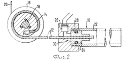
На диаграмме фиг. 1 в качестве кривой D нанесена характеристика давления газов, возникающих от пиротехнического газогенератора, который применяется для устройств натяжения ремня в удерживающих системах для ремней безопасности, в зависимости от времени t. На фиг. 2 схематически изображено устройство натяжения ремня с линейным приводом поршень-цилиндр 10, воздействующим через тяговый тросик 12 на окружность диска для тросика 14, присоединяемого с помощью соединительного механизма с зажимными роликами 16 к ременной катушке 18 устройства для намотки ремня, на которой намотана лента ремня 20. Линейный привод 10 состоит из цилиндра 22 и установленного в нем с возможностью перемещения поршня 24, который воздействует на свободный конец тягового тросика 12 и торцевая поверхность которого могут подводиться газы, находящиеся под высоким давлением, которые производит газогенератор 26, как только он запускается с помощью электрического или механического зажигательного устройства. В представленном на фиг. 2 выполнении устройства натяжения ремня поршень 24 неподвижно запрессован на конце тягового тросика 12. In the diagram of FIG. 1 as a curve D, a characteristic of the pressure of gases arising from a pyrotechnic gas generator, which is used for belt tension devices in restraint systems for seat belts, depending on time t, is plotted. In FIG. 2 schematically shows a belt tensioning device with a linear piston-
Газогенератор 26 вставлен в отверстие корпусного блока 28, в котором выполнен изогнутый канал 30, через который к торцевой поверхности поршня 24 направляются газы, произведенные газогенератором 26 при его зажигании. Как следует из фиг. 1, давление газа D при обычных выполнениях газогенератора 26 сначала круто нарастает и уже через 0,75 мс достигает максимума, составляющего около 76х106 Па. Вслед за тем давление падает почти так же круто и через приблизительно 2,5 мс составляет всего лишь около 10% от максимально достигаемого давления газа. Почти вся освобождаемая газогенератором энергия имеется в наличии, следовательно, в течение короткого промежутка времени, составляющего от 2 до 3 мс. Этот промежуток времени является существенно меньшим по сравнению с промежутком времени, требующимся поршню 24 для того, чтобы пройти отрезок пути, например, 250 мм до конца цилиндра 22.The
При линейном приводе, выполненном согласно изобретению, первая фаза осуществления которого изображена на фиг. 4, производимое поршнем 24 усилие передается на тяговый тросик 12 не непосредственно, а через демпфирующее устройство 32. Это демпфирующее устройство 32 образовано несколькими тарельчатыми пружинами, установленными последовательно на конце тягового тросика 12 и опирающимися с одной стороны на соседнюю торцевую поверхность поршня 24, а с другой стороны на неподвижно запрессованную на конце тягового тросика 12 упорную деталь 34. При активировании газогенератора 26, например, как показано на фиг. 4 с помощью ударного зажигания, поршень 24 продвигается вперед в цилиндре 10, причем тарельчатые пружины демпфирующего устройства 32 сжимаются, как только канатный шкив 14 через муфту 16 не скручиваясь, присоединяется к ременной катушке 18 и тяговый тросик 12 натягивается, так как должен быть преодолен момент инерции ременной катушки 18 и намотанной на нее ленты ремня 20. With a linear actuator according to the invention, the first phase of which is shown in FIG. 4, the force produced by the
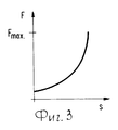
На фиг. 3 показано изменение создаваемого в тяговом тросике 12 тягового усилия F в зависимости от пройденного отрезка пути S. Как можно видеть из диаграммы, усилие F растет в начальной фазе движения поршня в виде прогрессии. Ременная катушка 18 теперь приводится во вращение за счет воздействующего на окружность канатного шкива 14 усилия 7 и достигает уже после прохождения короткого отрезка движения поршня, составляющего около 16 мм, экстремально высокого числа оборотов. In FIG. Figure 3 shows the change in the traction force F generated in the
Диаграмма на фиг. 1 показывает также изменение ускорения G поршня 24 в зависимости от времени t. На диаграмме можно видеть, что кривая G имеет форму, аналогичную кривой D, и в частности, ее вершина также достигается приблизительно при 0,75 мс. Давление газа D, следовательно, оптимальным образом преобразуется в ускорение поршня 24. Демпфирующее устройство является эффективным в продолжение всей начальной фазы движения поршня приблизительно до 1 мс. The diagram in FIG. 1 also shows the change in acceleration G of the
В диаграмме на фиг. 1 также изображен отрезок пути S, проходимый поршнем 24 в зависимости от времени t. Большую часть отрезка пути до конца цилиндра 10, например, в целом около 200 мм, поршень проходит при малом нагружении давлением. По прохождении приблизительно от 2,5 до 3 мс поршень 24 продвигается далее в цилиндре 22 вследствие его инерции масс. За счет выполнения разгрузочных отверстий в стенке цилиндра 10 приблизительно на половинной высоты его общей длины удалось доказать, что остаточное давление газа D вносит лишь малый вклад в увеличение мощности устройства натяжения ремня. Ременная катушка 18 продолжает вращательное движение в основном вследствие момента инерции. За счет демпфирующего устройства 32 согласно изобретению достигается то, что оптимизировано изменение усилия (см. фиг. 3) для того, чтобы обеспечивалось оптимальное аккумулирование энергии, освобожденной газогенератором в пределах самое большее приблизительно 3 мс, в форме механической энергии вращения ременной катушки 18 и намотанной на ней ленты ремня 20. Аккумулированной механической энергии достаточно для того, чтобы осуществить натяжение ленты ремня с помощью желаемого хода устройства натяжения ремня. In the diagram of FIG. 1 also shows a segment of the path S traveled by the
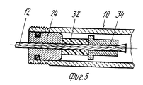
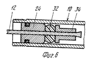
Две следующие формы осуществления демпфирующего устройства изображены на фиг. 5, 6 и 7, 8. The following two embodiments of the damping device are shown in FIG. 5, 6 and 7, 8.
При форме осуществления в соответствии с фиг. 5, 6 между поршнем 24 и упорной деталью 34 расположено демпфирующее устройство 32 в форме цилиндрического корпуса из упруго податливого материала с осевым проходом для тягового тросика 12. Как показано на фиг. 6, этот корпус при нарастании тягового напряжения в тяговом тросике 12 упруго и вместе с тем пластически деформируется. In the embodiment of FIG. 5, 6, a damping
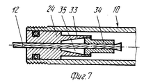
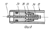
При форме осуществления в соответствии с фиг. 7, 8 на поршне 24 на его торцевой стороне, обращенной к упорной детали 34, выполнена стенка 33, наружная поверхность которой является цилиндрической и которая ограничивает объем 35 в форме усеченного конуса, соосного с цилиндром 10, расширяющийся к свободному концу стенки 33. Упорная деталь 34 при изображенном на фиг. 8 исходном состоянии проникает в наружный конец объема 35. Как только усилие тяги в тяговом тросике 12 нарастает, упорная деталь 34 втягивается далее в объем 35, причем стенка 33 раздается и пластически деформируется. На фиг. 8 показано это состояние. In the embodiment of FIG. 7, 8 on the
Согласно изображениям на фиг. 7, 8, 9, 10, 11, 12, 13, 14 форма осуществления пластины, проходящая в основном поперек тягового тросика, образует разжимной корпус упорной детали 34 стенки 33. Кромки на стороне пластины, направленной в сторону стенки 33, которая пластически деформируется, выполнены закругленными. Радиус закругления составляет около 1 мм, но также могут составлять приблизительно от 1 до 2 мм. According to the images in FIG. 7, 8, 9, 10, 11, 12, 13, 14, the embodiment of the plate, extending mainly across the traction cable, forms the expandable housing of the
При обеих формах осуществления (см. фиг. 6, 7, 8) в принципе достигается показанное на фиг. 3 изменение усилия. В зависимости от осуществления демпфирующего устройства изменение усилия F в зависимости от отрезка пути S может, однако, варьироваться, за счет назначения размеров демпфирующего устройства в любом случае возможна оптимизация изменения усилия той степени, что освобожденная газогенератором в течение короткого времени энергия оптимальным образом может передаваться на механизм устройства натяжения ремня для того, чтобы там быть аккумулированной в виде механической энергии и в течение длительного промежутка времени обеспечивать натяжение ленты ремня. With both forms of implementation (see FIGS. 6, 7, 8), as shown in FIG. 3 change of effort. Depending on the implementation of the damping device, the change in the force F depending on the length of the path S can, however, vary, due to the dimensioning of the damping device, in any case, it is possible to optimize the force change to the extent that the energy released by the gas generator for a short time can be optimally transmitted to the mechanism of the belt tension device in order to be accumulated there in the form of mechanical energy and to provide tension for a long period of time Ie belt tape.
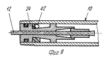
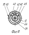
При форме осуществления в соответствии с фиг. 9, 10, которая в принципе совпадает с формой осуществления в соответствии с фиг. 6, на поршне 24 за счет сужения образована наклонная поверхность 40 в форме усеченного конуса, на самой глубокой части которой лишь на одной стороне поршня 24 за счет направляющей части 44 из упругого материала удерживаются с прилеганием к внутренней стороне цилиндра 10 три шарика 42. Как можно видеть из фиг. 10, направляющая часть 44 имеет два буртика 45, за счет которых шарики 42 удерживаются на названной стороне поршня 24. На радиально противолежащей стороне поршень 24 опирается со скольжением на внутреннюю сторону цилиндра 10. При движении поршня 24 под действием произведенного газогенератором давления газа шарики 42 не противодействуют этому движению. Как только в конце хода обратно натяжения за счет тяги в тяговом тросике 12 наступает изменение направления движения поршня 24, шарики 42, действующие теперь в качестве запорных шариков, вводятся в контакт со стенкой цилиндра 10, так как они отжимаются наклонной поверхностью 40 радиально наружу. При дальнейшем движении поршня 24 шарики 42 проникают в материал стенки цилиндра 10 и деформируют его пластическим образом. На фиг. 10 показано это состояние. Конструкция действует в соединении с натяжением ремня как преобразователь энергии, снимающий пики нагрузки в ременной системе. За счет применения лишь нескольких шариков предупреждаются пластические деформации цилиндра 10, которые приводили бы к неустойчивому преобразованию энергии и к возникновению колебаний нагрузки в ременной системе. До тех пор, пока вводимые через тяговый тросик 12 усилия не превышают величину приблизительно 5000 Н, что как раз может достигаться в соединении с оптимально действующим устройством натяжения ремня, преобразование энергии должно осуществляться с помощью лишь малого количества деформирующих элементов для того, чтобы каждый из них проникал в материал стенки цилиндра на относительно большую величину. In the embodiment of FIG. 9, 10, which in principle coincides with the embodiment in accordance with FIG. 6, an oblique
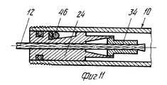
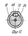
При форме осуществления в соответствии с фиг. 8 вместо трех шариков на фиг. 9, 10 используется валик 46, снабженный на концах со стороны торца закруглением, так что он мягко и без режущей обработки может проникать в материал стенки цилиндра. Принцип действия в основном, является таким же, что и в случае примера осуществления в соответствии с фиг. 9, 10. In the embodiment of FIG. 8 instead of the three balls in FIG. 9, 10, a
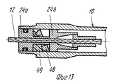
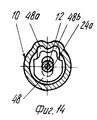
При форме осуществления в соответствии с фиг. 13, 14 поршень разделен на две части 24а, 24в, свободно расположенные последовательно на осевом расстоянии друг от друга на тяговом тросике 12. В объеме между частями поршня 24а, 24в, расположена пластина, наклоненная в соответствии с представленным на фиг. 9а исходном состоянии под углом приблизительно 30о к оси цилиндра 10. Пластина 48 на одном своем конце опирается со скольжением на внутреннюю сторону цилиндра 10, а на радиально противоположном конце снабжена двумя деформирующими элементами 48а, 48в. Клинообразная направляющая деталь 49 удерживает пластину 48 с ее деформирующими элементами 48а, 48в на внутренней стороне цилиндра 10 с прилеганием к ней упругим образом.In the embodiment of FIG. 13, 14, the piston is divided into two parts 24a, 24b, loosely arranged sequentially at an axial distance from each other on the
Пластина 48 не противодействует движению поршня 24а, 24в для натяжения ленты ремня, при противоположном движении она поднимается, так что деформирующие элементы 48а, 48в проникают в материал стенки цилиндра 10 и пластически деформируют его. Это состояние показано на фиг. 14. Принцип действия в основном является тем же, что и при формах осуществления в соответствии с фиг. 9 и 11. The
Claims (13)
Applications Claiming Priority (2)
| Application Number | Priority Date | Filing Date | Title |
|---|---|---|---|
| DE4206980 | 1992-03-05 | ||
| DEP4206980.7 | 1992-03-05 |
Publications (2)
| Publication Number | Publication Date |
|---|---|
| RU93004576A RU93004576A (en) | 1995-10-20 |
| RU2058905C1 true RU2058905C1 (en) | 1996-04-27 |
Family
ID=6453309
Family Applications (1)
| Application Number | Title | Priority Date | Filing Date |
|---|---|---|---|
| RU9393004576A RU2058905C1 (en) | 1992-03-05 | 1993-03-04 | Linear drive for safety belt system |
Country Status (10)
| Country | Link |
|---|---|
| US (1) | US5350194A (en) |
| EP (1) | EP0558963B1 (en) |
| JP (1) | JPH089318B2 (en) |
| CN (1) | CN1077166A (en) |
| CZ (1) | CZ279207B6 (en) |
| DE (1) | DE59307441D1 (en) |
| ES (1) | ES2047473T3 (en) |
| HU (1) | HUT70737A (en) |
| PL (1) | PL171590B1 (en) |
| RU (1) | RU2058905C1 (en) |
Families Citing this family (26)
| Publication number | Priority date | Publication date | Assignee | Title |
|---|---|---|---|---|
| DE4307062A1 (en) * | 1993-03-06 | 1994-09-08 | Trw Repa Gmbh | Belt tensioners for seat belt systems in vehicles |
| DE9304152U1 (en) * | 1993-03-20 | 1993-05-13 | Trw Repa Gmbh, 7077 Alfdorf, De | |
| US5531479A (en) * | 1995-01-20 | 1996-07-02 | Trw Vehicle Safety Systems Inc. | Vehicle seat belt restraint system |
| US5639120A (en) * | 1995-09-27 | 1997-06-17 | Ford Motor Company | Seat belt buckle pretensioner with end cap |
| US5564748A (en) * | 1995-09-27 | 1996-10-15 | Ford Motor Company | Seat belt buckle pretensioner with patterned frangible end cap |
| GB9601075D0 (en) * | 1996-01-19 | 1996-03-20 | Alliedsignal Ltd | Pretensioner |
| DE29607362U1 (en) * | 1996-04-23 | 1996-08-22 | Trw Repa Gmbh | Seat belt system |
| DE29612781U1 (en) * | 1996-07-23 | 1996-11-21 | Trw Repa Gmbh | Pyrotechnic linear drive device for a belt tensioner |
| DE29707352U1 (en) * | 1997-04-23 | 1997-08-21 | Trw Repa Gmbh | Tightener for a seat belt |
| DE29708880U1 (en) | 1997-05-20 | 1997-09-18 | Trw Repa Gmbh | Belt tensioners for a vehicle occupant restraint system |
| US5911433A (en) * | 1997-11-06 | 1999-06-15 | Trw Inc. | Vehicle occupant protection apparatus |
| US6039353A (en) * | 1997-12-24 | 2000-03-21 | Trw Vehicle Safety Systems Inc. | Apparatus for pretensioning seat belt webbing |
| JP3662739B2 (en) * | 1998-04-20 | 2005-06-22 | 本田技研工業株式会社 | Seat belt pretensioner |
| US20030122363A1 (en) * | 1999-01-11 | 2003-07-03 | Olaf Muller | Operating method and system for vehicle safety device |
| US6167808B1 (en) * | 1999-04-06 | 2001-01-02 | Trw Inc. | Initiator for air bag inflator |
| DE10018487C1 (en) * | 2000-04-14 | 2002-01-24 | Autoliv Dev | Automobile passenger seatbelt tensioning device has housing supported by deformable retaining element absorbing shock pulse upon release of gas generator |
| DE20102758U1 (en) * | 2001-02-16 | 2001-06-28 | Trw Repa Gmbh | Belt tensioners |
| NL1019869C2 (en) * | 2001-05-11 | 2002-11-12 | Whiplash Preventie Systems Hol | Pyrotechnic control device and seat equipped with it, as well as damping element to be used therein. |
| JP4622605B2 (en) * | 2005-03-18 | 2011-02-02 | タカタ株式会社 | Igniter assembly, inflator, airbag device, and seat belt device |
| DE102005049659B3 (en) * | 2005-10-18 | 2007-04-05 | Autoliv Development Ab | Tightening device for safety belt system in motor vehicle has piston, which is formed in form of olive, with radius in longitudinal direction of pipe is larger than effective radius in transverse direction of pipe |
| DE102006053563B4 (en) | 2006-11-14 | 2022-05-12 | Mercedes-Benz Group AG | Belt tensioner for a safety belt system |
| US7770924B2 (en) * | 2008-07-17 | 2010-08-10 | Autoliv Asp, Inc. | Liquid cooled hybrid |
| DE102011014127A1 (en) * | 2011-03-15 | 2012-09-20 | Trw Automotive Gmbh | linear actuator |
| CN103010151B (en) * | 2011-06-28 | 2015-06-10 | 常州博万达汽车安全设备有限公司 | Pre-tensioning device for seat safety belt |
| US9726216B2 (en) * | 2013-02-04 | 2017-08-08 | Shimano Inc. | Cable adjusting unit |
| DE102017201016A1 (en) | 2017-01-23 | 2018-07-26 | Volkswagen Aktiengesellschaft | Seat belt device for a vehicle |
Family Cites Families (17)
| Publication number | Priority date | Publication date | Assignee | Title |
|---|---|---|---|---|
| DE2304878C2 (en) * | 1973-02-01 | 1982-12-30 | Adam Opel AG, 6090 Rüsselsheim | Safety belt assembly for vehicles, in particular for motor vehicles |
| JPS49124731U (en) * | 1973-02-22 | 1974-10-25 | ||
| FR2239870A1 (en) * | 1973-08-03 | 1975-02-28 | Poudres & Explosifs Ste Nale | |
| DE2540952C2 (en) * | 1975-09-13 | 1984-08-16 | Volkswagenwerk Ag, 3180 Wolfsburg | Belt tensioning device for a seat belt |
| DE2809587A1 (en) * | 1977-03-09 | 1978-09-14 | Britax Wingard Ltd | TENSIONING DEVICE FOR A SAFETY BELT |
| DE2727123A1 (en) * | 1977-06-16 | 1978-12-21 | Daimler Benz Ag | ANCHORING OF AN END OR FOLDER POINT OF A SEAT BELT, ESPECIALLY IN CARS |
| JPS54153425A (en) * | 1978-05-23 | 1979-12-03 | Nippon Soken Inc | Seat belt tightening apparatus |
| FR2460407A1 (en) * | 1979-06-29 | 1981-01-23 | Angeviniere Sa | Seat belt blocking mechanism - has piston rod with slidable blocking ring tilting on carrier element inclined surface |
| JPS607973Y2 (en) * | 1979-08-02 | 1985-03-19 | 株式会社日本自動車部品総合研究所 | seat belt tightening device |
| DE3137263C2 (en) * | 1980-10-06 | 1985-12-19 | TRW Repa GmbH, 7071 Alfdorf | Cylinder / piston drive especially for tensioning systems in automatic seat belt winding machines |
| DE3131637C2 (en) * | 1980-10-06 | 1986-10-02 | TRW Repa GmbH, 7077 Alfdorf | Back tensioner for seat belt machines |
| US4441738A (en) * | 1980-12-30 | 1984-04-10 | Nippon Soken, Inc. | Seat belt tensioning device |
| DE3407379A1 (en) * | 1984-02-29 | 1986-06-26 | Autoflug Gmbh, 2084 Rellingen | Belt tightener for a self-locking safety belt retractor |
| DE8406217U1 (en) * | 1984-02-29 | 1985-09-12 | Autoflug Gmbh, 2084 Rellingen | Belt tensioner for a self-locking seat belt retractor |
| DE8816557U1 (en) * | 1988-03-22 | 1989-11-16 | Autoflug Gmbh & Co Fahrzeugtechnik, 2084 Rellingen, De | |
| DE3900024A1 (en) * | 1989-01-02 | 1990-07-05 | Schmidt Gmbh R | Locking device for a mechanical safety belt tensioning device |
| ATE114277T1 (en) * | 1989-05-13 | 1994-12-15 | Hs Tech & Design | LOCKING DEVICE AND DEVICE FOR TIGHTENING A SEAT BELT IN A VEHICLE, PARTICULARLY A MOTOR VEHICLE. |
-
1993
- 1993-02-10 EP EP93102057A patent/EP0558963B1/en not_active Revoked
- 1993-02-10 DE DE59307441T patent/DE59307441D1/en not_active Revoked
- 1993-02-10 ES ES93102057T patent/ES2047473T3/en not_active Expired - Lifetime
- 1993-02-24 US US08/021,774 patent/US5350194A/en not_active Expired - Fee Related
- 1993-03-02 PL PL93297914A patent/PL171590B1/en unknown
- 1993-03-03 CN CN93102306A patent/CN1077166A/en active Pending
- 1993-03-04 JP JP5043926A patent/JPH089318B2/en not_active Expired - Fee Related
- 1993-03-04 RU RU9393004576A patent/RU2058905C1/en active
- 1993-03-04 CZ CZ93331A patent/CZ279207B6/en unknown
- 1993-03-05 HU HU9300616A patent/HUT70737A/en unknown
Non-Patent Citations (1)
| Title |
|---|
| Выложенная заявка ФРГ N 2304878, кл. B 60R 21/10, опублик. 1978. * |
Also Published As
| Publication number | Publication date |
|---|---|
| US5350194A (en) | 1994-09-27 |
| JPH089318B2 (en) | 1996-01-31 |
| JPH068796A (en) | 1994-01-18 |
| PL297914A1 (en) | 1993-09-06 |
| DE59307441D1 (en) | 1997-11-06 |
| HUT70737A (en) | 1995-10-30 |
| ES2047473T1 (en) | 1994-03-01 |
| EP0558963B1 (en) | 1997-10-01 |
| ES2047473T3 (en) | 1998-01-16 |
| CZ279207B6 (en) | 1995-01-18 |
| HU9300616D0 (en) | 1993-05-28 |
| EP0558963A3 (en) | 1994-04-27 |
| EP0558963A2 (en) | 1993-09-08 |
| CZ33193A3 (en) | 1993-09-15 |
| CN1077166A (en) | 1993-10-13 |
| PL171590B1 (en) | 1997-05-30 |
Similar Documents
| Publication | Publication Date | Title |
|---|---|---|
| RU2058905C1 (en) | Linear drive for safety belt system | |
| US4573322A (en) | Driving device especially for return stiffening of a safety belt in an automatic safety belt wind-up device | |
| US5480190A (en) | Energy converter in a restraining system for vehicle occupants | |
| US4458921A (en) | Seat belt tensioning device | |
| US5358275A (en) | Energy converter in a restraining system for vehicle occupants | |
| US8220735B2 (en) | Adaptive load limiting retractor | |
| RU2088440C1 (en) | Mechanism for pulling in safety belt inward | |
| US4750685A (en) | Safety belt takeup device with tightening means | |
| US4444010A (en) | Rotary power element | |
| US4618108A (en) | Safety belt reel-in mechanism having a tensioning arrangement | |
| US6446897B1 (en) | Seat belt system | |
| US6712394B2 (en) | Belt tensioner | |
| KR102615602B1 (en) | Seatbelt pretensioning retractor assembly | |
| CN106255834A (en) | Isolator decoupler | |
| US3927846A (en) | Safety belt unwinding device with energy dissipator | |
| US5671894A (en) | Retractor with load limiting spool with decoupled pretensioner | |
| EP1201513B1 (en) | Soft-start piston actuator | |
| JP4246865B2 (en) | Seat belt device | |
| JP2023525699A (en) | retractor pretensioner assembly | |
| JPS6124217B2 (en) | ||
| US4381084A (en) | Re-tightener with pyrotechnic propellant charge for safety belt automatic wind-up devices | |
| JP4248106B2 (en) | Seat belt device | |
| US6416002B1 (en) | Assembly unit consisting of a belt retractor and a belt tensioner drive | |
| WO1996013409A1 (en) | Method for locking and load limiting of a seat belt | |
| JP2002347574A (en) | Seat belt device |