RU2049314C1 - Fluid medium pressure derivative sensor, pneumoelectric pressure relay and system warning about air leakage from pumped tire - Google Patents
Fluid medium pressure derivative sensor, pneumoelectric pressure relay and system warning about air leakage from pumped tire Download PDFInfo
- Publication number
- RU2049314C1 RU2049314C1 SU894742884A SU4742884A RU2049314C1 RU 2049314 C1 RU2049314 C1 RU 2049314C1 SU 894742884 A SU894742884 A SU 894742884A SU 4742884 A SU4742884 A SU 4742884A RU 2049314 C1 RU2049314 C1 RU 2049314C1
- Authority
- RU
- Russia
- Prior art keywords
- pressure
- diaphragm
- chamber
- channel
- sensor according
- Prior art date
Links
Images


Classifications
-
- H—ELECTRICITY
- H01—ELECTRIC ELEMENTS
- H01H—ELECTRIC SWITCHES; RELAYS; SELECTORS; EMERGENCY PROTECTIVE DEVICES
- H01H35/00—Switches operated by change of a physical condition
- H01H35/24—Switches operated by change of fluid pressure, by fluid pressure waves, or by change of fluid flow
- H01H35/34—Switches operated by change of fluid pressure, by fluid pressure waves, or by change of fluid flow actuated by diaphragm
- H01H35/346—Switches operated by change of fluid pressure, by fluid pressure waves, or by change of fluid flow actuated by diaphragm in which the movable contact is formed or directly supported by the diaphragm
-
- B—PERFORMING OPERATIONS; TRANSPORTING
- B60—VEHICLES IN GENERAL
- B60C—VEHICLE TYRES; TYRE INFLATION; TYRE CHANGING; CONNECTING VALVES TO INFLATABLE ELASTIC BODIES IN GENERAL; DEVICES OR ARRANGEMENTS RELATED TO TYRES
- B60C23/00—Devices for measuring, signalling, controlling, or distributing tyre pressure or temperature, specially adapted for mounting on vehicles; Arrangement of tyre inflating devices on vehicles, e.g. of pumps or of tanks; Tyre cooling arrangements
- B60C23/02—Signalling devices actuated by tyre pressure
- B60C23/04—Signalling devices actuated by tyre pressure mounted on the wheel or tyre
- B60C23/0408—Signalling devices actuated by tyre pressure mounted on the wheel or tyre transmitting the signals by non-mechanical means from the wheel or tyre to a vehicle body mounted receiver
-
- B—PERFORMING OPERATIONS; TRANSPORTING
- B60—VEHICLES IN GENERAL
- B60C—VEHICLE TYRES; TYRE INFLATION; TYRE CHANGING; CONNECTING VALVES TO INFLATABLE ELASTIC BODIES IN GENERAL; DEVICES OR ARRANGEMENTS RELATED TO TYRES
- B60C23/00—Devices for measuring, signalling, controlling, or distributing tyre pressure or temperature, specially adapted for mounting on vehicles; Arrangement of tyre inflating devices on vehicles, e.g. of pumps or of tanks; Tyre cooling arrangements
- B60C23/02—Signalling devices actuated by tyre pressure
- B60C23/04—Signalling devices actuated by tyre pressure mounted on the wheel or tyre
- B60C23/0491—Constructional details of means for attaching the control device
- B60C23/0494—Valve stem attachments positioned inside the tyre chamber
-
- H—ELECTRICITY
- H01—ELECTRIC ELEMENTS
- H01H—ELECTRIC SWITCHES; RELAYS; SELECTORS; EMERGENCY PROTECTIVE DEVICES
- H01H35/00—Switches operated by change of a physical condition
- H01H35/24—Switches operated by change of fluid pressure, by fluid pressure waves, or by change of fluid flow
- H01H35/26—Details
- H01H35/28—Compensation for variation of ambient pressure or temperature
Landscapes
- Physics & Mathematics (AREA)
- Fluid Mechanics (AREA)
- Engineering & Computer Science (AREA)
- Mechanical Engineering (AREA)
- Measuring Fluid Pressure (AREA)
- Transition And Organic Metals Composition Catalysts For Addition Polymerization (AREA)
- Medicines Containing Antibodies Or Antigens For Use As Internal Diagnostic Agents (AREA)
- Magnetic Resonance Imaging Apparatus (AREA)
- Switches Operated By Changes In Physical Conditions (AREA)
Abstract
Description
Изобретение относится к датчику давления, который реагирует на заданную скорость изменения давления (рабочей) текучей среды в системе, чувствительной к давлению. Такой датчик давления, может быть использован в индикаторной системе контроля давления воздуха в шинах автомобиля или другого транспортного средства, формирующей сигнал предупреждения, когда скорость изменения давления в шинах превышает опасный уровень. The invention relates to a pressure sensor that responds to a given rate of change of pressure of a (working) fluid in a pressure sensitive system. Such a pressure sensor can be used in an indicator system for monitoring the air pressure in the tires of a car or other vehicle, which generates a warning signal when the rate of change in tire pressure exceeds a dangerous level.
Известны пневмо- и гидрореле, которые срабатывают при изменении давления, генерируя сигнал предупреждения. В отличие от таких устройств, данный датчик давления реагирует на заданную скорость или темп изменения давления в компрессионной среде, а не на перепад давления. Known pneumatic and hydraulic relays that are triggered by a change in pressure, generating a warning signal. Unlike such devices, this pressure sensor responds to a given speed or rate of change in pressure in the compression medium, and not to a pressure drop.
В частности, в патенте США N 4211901 описано реле давления, преобразующее изменение пневмодавления в электрический сигнал. Это устройство реагирует на перепад давления между двумя камерами, разделенными диафрагмой. Конструктивно оно ориентировано на выполнение именно этой функции и не может регистрировать скорость изменения давления в пневмоиндикаторной системе, предназначенной для предупреждения опасных ситуаций, как это предусматривается настоящим изобретением. In particular, US Pat. No. 4,211,901 describes a pressure switch that converts a change in air pressure into an electrical signal. This device responds to pressure differences between two chambers separated by a diaphragm. Structurally, it is focused on the performance of this particular function and cannot register the rate of change of pressure in a pneumatic indicator system designed to prevent dangerous situations, as provided by the present invention.
В патенте США N 4048614, выданном Шамвею, описана радиопередающая система регистрации давления, выдающая сигнально-индикаторную информацию о давлении в шинах. Эта система генерирует сигнал аварийного предупреждения в случае падения давления в шинах ниже порогового минимального рабочего уровня. U.S. Patent No. 4,048,614 to Shumway describes a pressure transmitting radio transmission system that provides tire pressure alarm information. This system generates an alarm in the event that the tire pressure drops below the threshold minimum operating level.
На практике во многих случаях крайне необходимо иметь предупредительную информацию о падении давления в пневматиках ниже какого-то определенного критического уровня. Но в то же время при определенных условиях такое падение давления не является опасным. In practice, in many cases, it is imperative to have warning information about the pressure drop in the pneumatics below a certain critical level. But at the same time, under certain conditions, such a pressure drop is not dangerous.
Стенка пневмошины и уплотнение между шиной и ободом колеса в определенной степени проницаемы для воздуха, что приводит к постепенному падению давления в надутой шине в течение длительного времени. Такое крайне медленное понижение давления не представляет опасности, когда, к примеру, накачанная шина входит в состав шасси прицепа тягача, который не эксплуатируется, находясь в резерве в автопарке в течение нескольких месяцев. Это довольно распространенная ситуация, когда прицепы простаивают в автопарке или машинном дворе длительное время, и если шины таких транспортных средств снабжены тревожными сигнализаторами падения давления, их срабатывание будет происходить не часто. По этой причине такие сигнализаторы оснащаются маломощным аккумулятором; эти аккумуляторы подсаживаются при срабатывании сигнализации, что требует их замены перед постановкой сигнального устройства на очередное дежурство. Для этого необходимо демонтировать шину с обода колеса. В некоторых случаях срабатывание сигнализации и разрядка питающего электроаккумулятора могут не быть зафиксированы обслуживающим персоналом автопарка, и по существу отработавшие средства сигнализации будут считаться в рабочем состоянии. The wall of the pneumatic tire and the seal between the tire and the wheel rim are to some extent permeable to air, which leads to a gradual drop in pressure in the inflated tire for a long time. Such an extremely slow pressure decrease is not dangerous when, for example, the inflated tire is part of the chassis of the tractor trailer, which is not in operation, being in reserve in the fleet for several months. This is a fairly common situation when trailers are idle in a car fleet or in a machine yard for a long time, and if the tires of such vehicles are equipped with alarming pressure drops, their operation will not occur often. For this reason, such signaling devices are equipped with a low-power battery; these batteries are seated when an alarm is triggered, which requires replacement before placing the alarm device on the next standby. To do this, remove the tire from the wheel rim. In some cases, the alarm and the discharge of the power supply accumulator may not be recorded by the maintenance personnel of the fleet, and essentially the spent signaling means will be considered in working condition.
Для большинства колесных транспортных средств медленное падение давления в шинах не опасно. Как отмечалось выше, все шины в некоторой степени проницаемы и, естественно, со временем постоянно подспускают. Снижение давления становится опасным, когда скорость, с которой это происходит, такова, что давление в шине может упасть ниже критического порогового уровня в течение ее дорожной эксплуатации. For most wheeled vehicles, a slow drop in tire pressure is not dangerous. As noted above, all tires are somewhat permeable and, of course, constantly lower over time. Pressure reduction becomes dangerous when the speed at which this occurs is such that the pressure in the tire can drop below a critical threshold level during its road operation.
Целью изобретения является разработка датчика давления, реагирующего на определенную скорость изменения давления рабочей среды в пневмосистеме. The aim of the invention is the development of a pressure sensor that responds to a certain rate of change of pressure of the working medium in the pneumatic system.
Другой целью изобретения является разработка датчика давления, имеющего камеру повышенного давления, одна из стенок которой проницаема, с возможностью изменения давления в этой камере с заданной скоростью, при этом одна из стенок камеры выполнена в виде гибкой диафрагмы, которая смещается в определенное положение при заданном изменении перепада давления между камерой повышенного давления и контролируемой пневмосистемой, с которой сообщается датчик. Another objective of the invention is the development of a pressure sensor having a pressure chamber, one of the walls of which is permeable, with the possibility of changing the pressure in this chamber at a given speed, while one of the walls of the chamber is made in the form of a flexible diaphragm, which moves to a certain position at a given change differential pressure between the pressure chamber and the controlled pneumatic system with which the sensor communicates.
Дальнейшей целью данного изобретения является разработка индикаторной системы аварийной сигнализации о давлении в шинах, включающей в себя датчик давления, который реагирует на определенную скорость изменения воздушного давления в шине. Соответственно, частным целевым аспектом изобретения является создание датчика давления, рассчитанного на регистрацию заданной скорости изменения давления рабочей среды в контролируемой пневмосистеме; такой датчик содержит корпус со стенками, образующими камеру повышенного давления, причем одна из указанных стенок выполняется в виде гибкой диафрагмы, отделяющей камеру повышенного давления от указанной пневмосистемы и способной перемещаться возвратно-поступательно между первым и вторым рабочими положениями при определенном (заданном) изменении перепада давления между датчиковой камерой повышенного давления и контролируемой пневмосистемой, при этом, по меньшей мере, одна из указанных стенок проницаема по отношению к указанной рабочей среде, давая возможность последней проходить через нее со скоростью, позволяющей уравнять давление в указанной камере и пневмосистеме, предотвращая таким образом смещение диафрагмы во второе положение, при котором скорость изменения давления в пневмосистеме меньше той, которая определяется заданным пороговым значением; при этом проницаемая стенка достаточно непроницаема, препятствуя прохождению через нее рабочей среды со скоростью, которая будет исключать уравнивание давления в указанной камере и в контролируемой пневмосистеме со скоростью, которая исключит переход диафрагмы из первого положения во второе при заданной скорости изменения давления, реализуемой в упомянутой пневмосистеме. A further objective of the present invention is the development of an indicator system for alarming tire pressure, including a pressure sensor that responds to a certain rate of change of air pressure in the tire. Accordingly, a particular target aspect of the invention is the creation of a pressure sensor designed to record a given rate of change of pressure of the working medium in a controlled pneumatic system; such a sensor comprises a housing with walls forming a pressure chamber, one of these walls being made in the form of a flexible diaphragm separating the pressure chamber from the specified pneumatic system and able to move back and forth between the first and second working positions at a certain (specified) change in pressure drop between the pressure sensor chamber and the controlled pneumatic system, while at least one of these walls is permeable with respect to the specified work whose medium, allowing the latter to pass through it at a speed that makes it possible to equalize the pressure in the specified chamber and the pneumatic system, thereby preventing the diaphragm from shifting to a second position at which the rate of change of pressure in the pneumatic system is less than that determined by a predetermined threshold value; in this case, the permeable wall is quite impenetrable, preventing the passage of the working medium through it at a speed that will exclude equalization of pressure in the specified chamber and in the controlled pneumatic system with a speed that will prevent the diaphragm from moving from the first position to the second at a given rate of pressure change implemented in the said pneumatic system .
В соответствии с другим аспектом настоящего изобретения, предложено пневмоэлектрическое датчиковое реле для регистрации опасной скорости изменения давления в рабочей пневмосистеме, содержащее корпус со стенками, образующими камеру повышенного давления, гибкую диафрагму, смонтированную в указанном корпусе, образующую одну из стенок камеры повышенного давления и отделяющую последнюю от пневмосистемы в процессе ее использования, причем диафрагма выполнена с возможностью свободного независимого возвратно-поступательного перемещения между первым и вторым положениями при опасной скорости изменения давления в системе, при этом одна из указанных стенок камеры повышенного давления проницаема, позволяя воздуху проходить через нее со скоростью, обеспечивающей уравнивание давления с противоположных сторон диафрагмы со скоростью, которая препятствовала бы детектированию изменения давления в указанной пневмосистеме, которое происходит со скоростью, меньшей упомянутой опасной скорости, при этом указанная проницаемая стенка достаточно непроницаема для того, чтобы воспрепятствовать проходу воздуха через нее со скоростью, исключающей уравнивание давления с противоположных сторон диафрагмы со скоростью, которая препятствовала бы переходу диафрагмы из первого положения в второе при опасной скорости изменения давления в контролируемой пневмосистеме; выключательное средство, смонтированное на указанном корпусе и сообщающееся с диафрагмой, открываясь и закрываясь в соответствии с перемещением диафрагмы возвратно-поступательно между первым и вторым положениями. In accordance with another aspect of the present invention, there is provided a pneumatic-electric sensor relay for detecting a dangerous rate of pressure change in a working pneumatic system, comprising a housing with walls forming a pressure chamber, a flexible diaphragm mounted in said body, forming one of the walls of the pressure chamber and separating the latter from the pneumatic system in the process of its use, and the diaphragm is made with the possibility of free independent reciprocating movement between the first and second positions at a dangerous rate of pressure change in the system, while one of the walls of the pressure chamber is permeable, allowing air to pass through it at a speed that ensures equalization of pressure from opposite sides of the diaphragm with a speed that would prevent the detection of pressure changes in the specified pneumatic system, which occurs at a speed less than the mentioned dangerous speed, while the specified permeable wall is sufficiently impenetrable to to stagnate the passage of air through it at a speed that excludes equalization of pressure from opposite sides of the diaphragm with a speed that would prevent the diaphragm from moving from the first position to the second at a dangerous rate of pressure change in the controlled pneumatic system; a switch means mounted on said housing and communicating with the diaphragm, opening and closing in accordance with the movement of the diaphragm reciprocatingly between the first and second positions.
Предложена также усовершенствованная индикаторная система предупредительной сигнализации, используемая для контроля накачки надувной камеры шины до заданного давления и генерирующая сигнал предупредительного оповещения при утечках воздуха из накачанной камеры с опасной скоростью. В состав этой системы входят: корпус, смонтированный в надувной камере колеса и имеющий стенку, образующую рабочую камеру повышенного давления; гибкая диафрагма, смонтированная в указанном корпусе, образующая одну из стенок камеры повышенного давления и отделяющая последнюю от надувной камеры, при этом диафрагма может свободно перемещаться возвратно-поступательно между первым и вторым положениями при опасной скорости изменения давления в надувной камере, причем одна из указанных стенок указанной камеры повышенного давления проницаемая в степени, достаточной для пропускания воздуха со скоростью, позволяющей уравнивать давление в упомянутой камере повышенного давления и надувной камере шины с противоположных сторон от диафрагмы со скоростью, при которой исключается детектирование изменения давления в указанной надувной камере со скоростью, меньше опасности скорости, при этом указанная проницаемая стенка относительно непроницаема, т.е. она препятствует прохождению воздуха через нее со скоростью, которая исключит уравнивание давления между камерой повышенного давления и надувной камерой шины с противоположных сторон диафрагмы со скоростью, которая препятствовала бы перемещению диафрагмы из первого положения во второе при реализации опасной скорости изменения давления в пневмоиндикаторной системе; сигнальное средство, функционально связанное с указанной диафрагмой и предназначенное для генерирования сигнала предупреждения при переходе диафрагмы из первого положения во второе. An improved warning indicator system is also used, which is used to control the inflation of the inflatable tire chamber to a predetermined pressure and which generates a warning signal when air leaks from the inflated chamber at a dangerous speed. The composition of this system includes: a housing mounted in an inflatable wheel chamber and having a wall forming a working chamber of high pressure; a flexible diaphragm mounted in the specified housing, forming one of the walls of the pressure chamber and separating the latter from the inflatable chamber, while the diaphragm can freely move back and forth between the first and second positions at a dangerous rate of pressure change in the inflatable chamber, one of these walls the specified pressure chamber permeable to a degree sufficient to allow air to pass at a speed that allows you to equalize the pressure in the said pressure chamber and above implicit tire chamber on opposite sides of the aperture at a speed at which excluded detection of change of pressure in said inflatable chamber at a rate less hazard rate, said permeable wall is relatively impermeable, i.e. it prevents the passage of air through it at a speed that eliminates the equalization of pressure between the pressure chamber and the inflatable tire chamber from opposite sides of the diaphragm with a speed that would prevent the diaphragm from moving from the first position to the second when a dangerous rate of pressure change in the pneumatic indicator system is realized; signal means operatively associated with said diaphragm and intended to generate a warning signal when the diaphragm moves from the first position to the second.
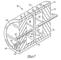
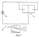
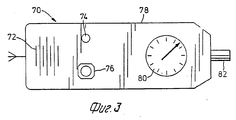
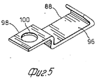
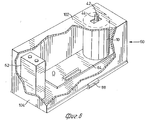
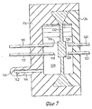
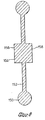
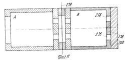
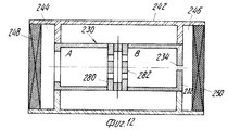
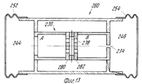
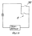
На фиг.1 в продольном разрезе в изометрии сбоку показано пневмоэлектрическое реле, сконструированное в соответствии с изобретением, на фиг.2 приведена принципиальная схема пневмоиндикаторного передающего сигнального устройства, в состав которого входит пневмореле, показанное на фиг.1; на фиг.3 схематично показан общий вид приемника, используемого в сочетании с пневмоиндикаторным устройством, представленным на фиг.2; на фиг.4 приведено поперечное сечение шины и показано размещение передатчика и пневмореле на ободе колеса (внутри надувной камеры шины); на фиг.5 в общем виде показан установочный кронштейн, используемый в сборке фиг.4; на фиг.6 cхематично в общем виде с вырывом показано пневмоиндикаторное сигналопередающее устройство; на фиг. 7 продольный разрез части пневмореле, на фиг.8 поперечное сечение диафрагмы пневмореле, изображенного на фиг.7; на фиг.9 разрез ручного насоса для накачки шин с системой контроля давления,вариант изобретения; на фиг.10 схема датчика давления (1 резервуар, 2 дроссельное отверстие, 3 пластинчатая диафрагма, 5 плунжер); на фиг. 11-13 схемы датчика давления, варианты изображения; на фиг.14 схема контура, состоящего из термореле и последовательно подключенного с ним передатчика. Figure 1 is a longitudinal section in isometric side view of a pneumatic electric relay constructed in accordance with the invention, figure 2 shows a schematic diagram of a pneumatic indicator transmitting signal device, which includes a pneumatic relay, shown in figure 1; figure 3 schematically shows a General view of the receiver used in combination with the pneumatic indicator device shown in figure 2; figure 4 shows the cross section of the tire and shows the placement of the transmitter and pneumatic relay on the wheel rim (inside the tire inflatable chamber); figure 5 in General view shows the mounting bracket used in the assembly of figure 4; Fig.6 schematically in General view with a pull out shows a pneumatic indicator signal transmitting device; in FIG. 7 is a longitudinal section through a portion of a pneumorelay, in FIG. 8 a cross-section of the diaphragm of a pneumorelay depicted in FIG. 7; Fig.9 is a section of a hand pump for inflation of tires with a pressure control system, an embodiment of the invention; figure 10 diagram of the pressure sensor (1 reservoir, 2 throttle bore, 3 plate diaphragm, 5 plunger); in FIG. 11-13 pressure sensor circuits, image options; on Fig circuit diagram, consisting of a thermal relay and a series-connected transmitter.
Пневмоэлектрическое реле (выключателя) (1-й вариант изобретения) содержит корпус 12, состоящий из трех функциональных элементов 14, 15 и 16. Элемент 14 представляет собой цилиндрическую гильзу 20 с отверстием и выполняется из электропроводящего материала типа латуни или меди. The pneumatic-electric relay (switch) (1st embodiment of the invention) comprises a
Комплектующая деталь 16 выполняется из электроизолирующего материала и имеет цилиндрическую боковую стенку 26 и торцевую стенку 28. Цилиндрическая боковая стенка 26 имеет торцевую грань 30, которая обращена наружу и скошена наружу и назад в направлении торцевой стенки 28. Цилиндрическая боковая стенка 26 входит в отверстие 20 гильзы 14, занимая соответствующую часть его длины. Деталь 15 выполнена из изолирующего материала и имеет цилиндрическую боковую стенку 24 и торцевую стенку 18. В свою очередь, боковая стенка 24 имеет торцевую грань 22, которая скошена наружу и назад в сторону торцевой стенки 18. Гибкая диафрагма 32 имеет периметральное установочное кольцо 34 и тонкую гибкую мембрану 36. Установочная кольцевая часть 34 диафрагмы защемляется между торцевыми гранями 22 и 30. Достаточно очевидно, что при плотном поджатии к торцевой грани вкладыша 14 установочное кольцо 34 будет иметь надежный электрический контакт с ним. The
Детали 14, 15 и 16 корпуса 12 и гибкая диафрагма 32 в сборе, как это показано на фиг.1, образуют первую и вторую камеры 38, 40 повышенного давления, разделенные мембранной частью диафрагмы. Вторая камера давления 40 является герметично замкнутой. Первая камера 38 имеет сообщающий канал 42, который проходит через штуцер 44, в начальный момент перекрытый разрушаемой торцевой стенкой 46. Детали 14, 15 и 16 и диафрагму собирают в атмосфере под контрольным давлением, которое должно создаваться в процессе эксплуатации данного пневмореле в его второй камере 40. Если реле предназначается для использования в шине автомобиля или другого колесного средства; контрольное давление составляет порядка 100 фунтов/квадратный дюйм (7,031 кгс/см2).
В торцевой стенке 28 закреплен первый клеммный токовод 48, который входит в первую камеру 38 повышенного давления. Внутренний конец 5 проводника 48 несколько удален от диафрагмы 32, образуя первую электроконтактную клемму 50. In the
В торцевой стенке 18 закреплен второй клеммный токовод 56, который выходит через указанную стенку в камеру 40. Его внутренний конец образует вторую контактную клемму 58, которая в нормальном положении находится на некотором расстоянии от мембраны 36 (см.фиг.1). Рекомендуется, чтобы контактные клеммы 58 и 50 были равноудалены от мембраны 36 диафрагмы. При наличии перепада давления между камерами 38 и 40 гибкая мембрана 36 будет изгибаться в сторону камеры с низким давлением и при определенном перепаде будет приходить в контакт с соответствующей упорной клеммой 50 или 58, надежно замыкая цепь и давая возможность таким образом проходить электрическую току через деталь 14, диафрагму 32 и один из тоководов 48 или 56 в зависимости от того, какой из них находится в контакте с мембраной 36 диафрагмы. A second terminal
Гибкая диафрагма 32 выполняется из электропроводящего силиконового каучука, например из каучука, выпускаемого канадской фирмой Армет Индастриз Корпорейшн ов Тилсонбург. Принято считать что этот материал непроницаем по воздуху в нормальных условиях. Однако при наличии перепада давления между камерами 38 и 40 в течение длительного времени (порядка несколько суток) через мембрану 36 может пройти значительное количество воздуха. Вследствие постепенного уравнивания давления, что обусловлено некоторой проницаемостью мембраны 36, последняя не будет изгибаться до контакта с тоководными клеммами до тех пор, пока скорость наращивания давления в камере 40 не начнет превышать скорость, с которой сжатый воздух (пневмосреда) просачивается через мембрану 36. The
При создании в камерах 38 и 40 начального давления, близкого к рабочему давлению в контролируемой системе, мембрана 36, как можно предположить, будет находиться в нейтральном положении. При необходимости использования данного пневмоэлектрического реле (датчика) с его штуцера 44 удаляется торцевая заглушка 46, в результате чего открывается проходной канал 42. Затем этот канал подключается к той пневмосистеме, которая должна подвергаться контролю, в результате чего давление, действующее в этой системе, передается в первую камеру 38. В том случае когда перепад давления между камерами 38 и 40 превышает то расчетное значение, в пределах которого данное реле должно оставаться открытым, гибкая мембранная часть 36 диафрагмы 32 изогнется до контакта с одной из тоководных клемм 50 или 58, замыкая цепь реле 10. Если сборка этого реле осуществляется в среде с избыточным давлением, в камерах 38 и 40 сразу же создается соответствующее давление, которое обычно задается равным нормальному рабочему давлению. Перепад давления, имевшийся первоначально, постепенно уменьшается вследствие постепенного просачивания воздуха через мембрану 36. В камерах 38 и 40 давление воздуха сохраняется благодаря наличию торцевой заглушки, перекрывающей канал 42. When creating in the
Как показано на фиг.2, рассматриваемое пневмоэлектрическое реле 10 может быть применено в радиопередающем индикаторе 60 для контроля давления. В состав этого индикатора 60 входит источник питания в виде аккумуляторной (электрической) батареи 62 и передатчик 64. В том случае когда такой индикатор используется в системе сигнализации о давлении накачки колесных шин, как на фиг.2, в нем в качестве источника питания может служить одна или несколько 1,5-вольтовых батареек серии АА с увеличенным сроком эксплуатации, а в качестве передатчика стандартный коротковолновый радиопередатчик типа, применяемого для управления открыванием-закрыванием гаражных дверей и т.п. As shown in FIG. 2, the
На фиг. 3 показан портативный приемник 70, предназначенный для использования в паре с передающим индикатором, представленным на фиг.2. Приемник 70 может иметь обычную конструкцию и по своим рабочим характеристикам должен быть совместим с радиопередатчиком 64. Приемник 70 имеет звуковое сигнальное устройство 72 и оптическое сигнальное устройство 74. Звуковой сигнализатор 72 может быть выполнен в виде сирены, а оптический сигнализатор в виде индикаторной лампы-мигалки. Для отключения схемы сигнализации приемника используется кнопка-блокиратор 76. На практике достаточно широко представлены и хорошо известны разнообразные приемники-сигнализаторы, которые генерируют звуковые сигналы предупреждения и активируют визуально воспринимаемые индикаторы в ответ на поступление заданного сигнала; поэтому нет необходимости подробно рассматривать конструкцию приемника 70. Этот приемник смонтирован в портативном корпусе 78, в котором одновременно может находиться и обычный датчик давления или манометр 80. Манометр 80 имеет штуцер 82, который может подключиться к ниппелю шины или подобному средству. Манометр предназначается для оперативного контроля давления накачки шин или других подобных технических средств при подключении к ним штуцера 82. In FIG. 3 shows a
На фиг.4 индикатор давления 60 показан размещенным внутри надувной камеры 84 колесной шины 86. Индикатор 60 смонтирован на кронштейне-держателе 88, который, в свою очередь, закреплен на внутреннем конце 90 корпуса ниппеля 92, смонтированного на ободе колеса 94. 4, a
Упомянутый установочный кронштейн 88 показан на фиг.5. Он имеет посадочную часть 96 и установочную фланцевую часть 98, в которой выполнено крепежное отверстие 100, соответствующее по размеру стержневому корпусу 92 ниппеля шины. Посадочная часть 96 имеет профиль "ласточкина хвоста". Said mounting
На фиг.6 показана сборка индикатора давления 60, размещенного в корпусе 102, который имеет основание 104 с сечением в виде ласточкина хвоста, соответствующим профилю кронштейна 88. В корпусе 102 находятся батарея 62, передатчик 64 и пневмоэлектрическое реле 10, штуцер 44 которого выступает наружу через стенку корпуса 102, так что при установке после снятия торцевой заглушки 46 (см.фиг.1) входной канал 41 связывается с объемом надувной камеры 84 шины (см.фиг.4). Figure 6 shows the assembly of a
На фиг.7 представлен вариант исполнения пневмоэлектрического датчикового реле. В этом варианте в торцевой стенке 114 параллельно друг другу на некотором удалении закреплены проводники 110 и 112, образующие на концах контактные клеммы 116 и 118. Аналогичные тоководы 120 и 122 имеются в торцевой стенке 124, они образуют клеммы 126 и 128 с противоположной стороны диафрагмы 132. В штуцере 144 имеется входной канал 142, выходящий в первую камеру 138 повышенного давления. В исходном состоянии канал 142 заглушен наконечником 146. При работе данного реле его диафрагма 132, изгибаясь, приходит в контакт либо с клеммами 116, 118, либо с клеммами 126, 128 в зависимости от направления ее деформирования. При контакте диафрагмы с клеммами 116, 118 электрический ток проходит от проводника 110 к проводнику 112. Аналогичным образом при контакте диафрагмы 132 с клеммами 126 и 128 ток течет через проводник 120 к проводнику 122. Figure 7 presents an embodiment of a pneumoelectric sensor relay. In this embodiment,
В дальнейшей модификации (не показана) в данном реле предусматривается использование только одной группы контактов 116, 118 с одной стороны диафрагмы. Соответственно, в этом случае перемещение диафрагмы будет иметь однонаправленное, одностороннее результирующее действие по замыканию-размыканию контактов 116 и 118. In a further modification (not shown), this relay provides for the use of only one group of
Диафрагма, используемая в варианте пневмореле, представленном на фиг.7, показана в поперечном сечении на фиг.8. В ее конструкцию входит кольцевая образующая 150, гибкая мембрана 152 и центральное утолщение 154. Диафрагма выполняется из гибкого материала, способного проводить электрический ток. При зажатии периферийного кольца 152 между заплечиком 24 и торцевой гранью 30 (см.фиг.1) оно деформируется, принимая треугольную форму, как на фиг.1, и фиксируя таким образом кольцо 150 в посадочном корпусе. The diaphragm used in the version of the air valve shown in Fig.7 is shown in cross section in Fig.8. Its design includes an
Центральное утолщение 154 (cм. фиг.7) имеет плоские торцы 156 и 158, приводимые в контактное взаимодействие с концевыми клеммами 116, 118 и 126, 128. Утолщение 154 и стенка (мембрана) 152 имеют круглую форму на виде с торца. The central bulge 154 (see FIG. 7) has flat ends 156 and 158 which are brought into contact with the
Как указывалось выше, при сборке пневмореле камеры 38 и 40 выдерживают под давлением, приблизительно равным давлению окружающей среды, в которой должно эксплуатироваться реле. При использовании в надувной камере шины колесного транспортного средства камеры 38 и 40 должны поддерживаться под давлением порядка 100 фунтов на кв. дюйм (7,03 кгс/см2). При таком изначальном давлении реле может находиться в режиме эксплуатации длительное время, так как его рабочая диафрагма будет испытывать незначительный перепад давления между камерами 38 и 40, причем любой начальный перепад давления будет компенсироваться за счет проницаемости стенки 36 диафрагмы. При вводе в действие пневмореле в том виде, как это показано на фиг.4, удаляется торцевая заглушка 46 подсоединительного штуцера, открывая канал 42. В результате давление в камере 38 упадет и мембрана 36, изгибаясь, придет в контакт с электрической клеммой 50. Эта операция необходима для проверки работоспособности передатчика сигнала предупреждения. После установки рассматриваемого датчикового пневмоэлектрического реле производится накачка камеры 84 шины до необходимого давления. Давление накачки передается в рабочую камеру 38 пневмореле, отклоняя мембрану 36 (стенку ее диафрагмы) обратно в нейтральное положение. В случае перекачки шины мембрана 36, отклоняясь, приходит в контакт с клеммой 58, снова подключая передатчик, генерирующий сигнал предупреждения. После того как шина приведена в нормальное состояние, мембрана 36 будет находиться в положении, предельно близком к нейтральному. При наличии перепада давления между надувной камерой 84 и опорной камерой 40 этот перепад постепенно будет уменьшаться со временем вследствие воздухопроницаемости мембраны 36. Как уже отмечалось, даже те диафрагмы, которые считаются непроницаемыми, в действительности частично проницаемы, пропуская какое-то количество воздуха со временем, что приводит в конечном итоге к компенсации перепада давления через достаточно длительное время. Однако если давление в надувной камере шины 84 уменьшается или увеличивается в недопустимой степени со скоростью, которая превосходит скорость просачивания воздуха через мембрану 36, последняя будет изгибаться и в конечном итоге придет в контакт с концевой тоководной клеммой 50 или 58, подключая передатчик, который, в свою очередь, подаст сигнал предупреждения, от которого сработают сигнальные механизмы приемника.As mentioned above, during assembly of the pneumatic relay, the
На фиг. 9 показан вариант исполнения изобретения индикаторно-сигнализационная система 160 контроля давления в пневматической колесной шине. In FIG. 9 shows an embodiment of the invention, an indicator and
Эта система 160 содержит корпус 162, в котором образована камера 164 повышенного давления. На одном конце корпуса 162 смонтировано пневмоэлектрическое датчиковое реле 166 и образующее стенку камеры 164 повышенного давления. Реле 166 заключено в концевую крышку 168, которая выполнена из электропроводящего материала и имеет торцевую стенку 170 с несколькими проходными каналами 172, через которые пневмосреда может проходить возвратно между камерами 262 и 173. Кроме этого, в крышке-корпусе 168 имеется трубчатая стеночная часть 174, которая плотно посажена в конец корпуса 162. Внутри трубчатой стенки 174 имеется электроизолирующая втулка 176. Внутри реле 166 имеется гибкая диафрагма 178, которая фиксируется по периферии сепаратором 180, имеющим сквозные каналы 182, через которые передается пневмодавление в камере 164 к одной из сторон диафрагмы 178. Передатчик и батарея (не показаны) могут располагаться внутри камеры 164 повышенного давления, имея соответствующие электросоединения. При этом сепаратор 180 и концевая крышка 168 выполняются из электропроводящего материала, а втулка 176, выполняемая из электроизоляционного материала, исключает прямой электрический контакт между сепаратором 180 и концевой крышкой-корпусом 168. Диафрагма 178 выполняется из электропроводящего материала и находится в контакте с сепаратором 180 в нормальном состоянии, показанном на фиг.9. В этом случае когда давление в камере 164 превосходит давление в камере шины на величину, соответствующую заданному пороговому перепаду между давлением в камере 164 и камере шины, в котором смонтирован данный индикатор, диафрагма 178 отжимается до контакта с торцевой стенкой 170 концевой крышки-корпуса 168, замыкая соответствующую электрическую цепь и активируя передатчик. This
На корпусе 162 имеется торцевая крышка 260, которая образует предкамеру 262, которая сообщается с диафрагмой 178 через канал 172. В крышке 260 выполнено небольшое отверстие 264, которое служит для того, чтобы давление в этой предкамере не увеличивалось не уменьшалось со скоростью, сравнимой со скоростью изменения давления в надувной камере шины в процессе движения колеса по дорожному полотну или покрытию. В дополнение к этому торцевая крышка служит в качестве "демпфера", который блокирует возникновение на диафрагме "пиковых" давлений. В то же время следует подчеркнуть, что канал 264 достаточно велик по диаметру, давая возможность давлению в предкамере 262 увеличиваться со скоростью, значительно превосходящей ту скорость, которая необходима для регистрации опасной скорости изменения давления накачки шины колеса. On the
Вторая торцевая стенка 184 камеры 164 повышенного давления имеет первый выступ 186, который выходит в камеру давления 164. Через вторую торцевую стенку 184 проходит питающий канал 188, который выходит поперечно наружу через выступ 186. Выступ 186 закрыт трубчатой манжетой 190, выполненной из непроницаемого упругого материала и перекрывающей выходное отверстие канала 188. Аналогичный выступ 192 отходит наружу от перегородки 184; в этом выступе имеется подводящий сквозной канал 194, перекрытый в нормальном состоянии манжетой 196. Изнутри на торце второй стенки 184 имеется фильтр 198, который служит для очистки используемой пневмосреды перед ее выходом из камеры повышенного давления по выпускному каналу 194. Аналогичный фильтр 200 имеется и на внешнем торце стенки 184; он служит для фильтрации пневмосреды перед тем, как она пройдет через впускной канал 188. The second end wall 184 of the
Рассматриваемая сборка имеет обычный ниппельный штуцер 202 с упорным фланцем 204 на внутреннем конце, плотно посаженном в камере 206 с упором в торцевую стенку 208. Этот штуцер имеет проходной канал 210 и внешний конец 212 с внешней клапанной резьбой 214 Шрадера, на которую навинчивается обычный защитный колпачок; на внутреннем конце штуцер 202 имеет резьбу 216, предназначенную для закрепления данной клапанной сборки по месту использования. Фланец 204 рассматриваемого штуцера отделен от фильтра 192 распорной деталью 218, которая образует дополнительную камеру 220. Следует обратить внимание на то, что камера 164 повышенного давления, камеры 206 и 220, имеющие в данном случае круглое поперечное сечение, могут быть профилированы любым необходимым образом. При использовании узел пневмореле 160 устанавливается на обод колеса так, чтобы штуцер 202 выступал наружу, а корпус 162 находился внутри надувной камеры шины. В резьбовой внешний конец 212 ввинчивается обычный одноходовой клапан (ниппель), после чего может производиться накачка шины. При накачке шины воздух проходит через канал 210 и входит в камеру 206, из которой по каналу 222 он попадает в надувную камеру шины. С увеличением давления в шине воздух будет входить в камеру 220 по каналу 224, далее через фильтр 200 и выпускной канал 188. При этом давление в камере 220 будет достаточным для принудительного смещения трубчатой манжеты 190 и открывания питающего канала 188, идущего в камеру 164 повышенного давления. Воздух будет проходить через канал 188 до тех пор, пока перепад давления между камерами 220 и 164 ни вызовет отжатие манжеты 190 и перекрывание указанного канала. Необходимо обратить внимание на то, что манжета 190 препятствует возрастанию давления в компрессионной камере 164 сверх давления в камере 220 на начальной стадии накачки шины и служит для поддержания давления в камере 164 на уровне, несколько ниже, чем в накачиваемой камере шины. Перепад давления, создаваемый манжетой 190, больше необходимого для изгибающего отклонения диафрагмы 178 до контакта с разделительно-упорной стенкой-сепаратором 180. В результате этого на начальной стадии накачки диафрагма 178, отклоняясь, будет находиться в контакте с указанной стенкой 180, упираясь в нее. Наличие такой стенки гарантирует неповреждение диафрагмы в тех случаях, когда перепад давления между накачиваемой камерой шины и камерой 164 превосходит предельно-допустимое значение. Следует отметить, что на начальной стадии накачки пневмошины общепринято доводить давление до уровня, существенно превосходящего нормальное рабочее давление, это делается для того, чтобы шина "села" соответствующим образом на обод колеса. После того как шина накачана до такого "посадочного" давления, из нее через ниппель воздух несколько подспускается, в результате чего давление в камере шины может упасть ниже давления в камере 164. В этом случае воздух может быть выпущен из камеры 164 через выпускной канал 194 при отводе, отгибании манжеты 196. Выпуск воздуха будет продолжаться до тех пор, пока давление в накачанной камере шины не упадет ниже нормального рабочего давления. В этом случае перепад давлений между камерой 164 и надувной камерой шины таков, что давление в камере 164 превосходит давление в шине на величину, большую необходимой для отклонения диафрагмы 178 до контакта с торцевой стенкой 170, в результате чего произойдет включение передатчика. После этого производится подкачка шины с целью увеличения давления в ее камере до необходимого рабочего давления. В результате давление в камере шины снова станет больше, чем в компрессионной камере 164. По мере уменьшения перепада давлений при прохождении воздуха через канал 188 давление в компрессионной камере будет оставаться несколько ниже, чем в камере шины и, следовательно, передатчик будет находиться в отключенном состоянии. В последующем благодаря некоторой проницаемости диафрагмы будет происходить постепенное уменьшение перепада давлений и возврат диафрагмы в нейтральное положение. В результате этого процесса в дальнейшем при постепенном выпускании воздуха из накачанной шины и падении давления в ней произойдет срабатывание сигнального устройства, входящего в рассматриваемую систему. Сигнализация отключается при повторной накачке шины до рабочего давления, причем повторно сигнализация может включиться только в том случае, если в камере шины произойдет опасный перепад давления. The assembly in question has a conventional nipple fitting 202 with a
Если в результате быстрой утечки давление в камере шины падает с опасной скоростью, которая превосходит скорость просачивания воздуха через диафрагму 178, последняя будет изгибаться, приходя в контакт с торцевой стенкой 172 и включая передатчик (как указывалось выше), который, в свою очередь, включает систему предупредительной сигнализации. В результате будет генерироваться сигнал предупреждения. Если же давление в надувной камере шины уменьшается или увеличивается со скоростью, меньшей того значения, которое является опасным для шины, диафрагма 178 благодаря определенной проницаемости не будет отклоняться до контакта с торцевой стенкой 178 и, как следствие, передатчик не будет задействован. If, as a result of a quick leak, the pressure in the tire chamber drops at a dangerous speed that exceeds the rate of air leakage through the
Пневморелейная система контроля давления (фиг.9) может быть установлена на любую пневматическую шину независимо от необходимого давления ее холодной накачки. Это давление составляет обычно 28-30 фунтов на квадратный дюйм (1,96-2,1 кгс/см2) для автомобилей и 80-100 фунтов/кв.дюйм (5,62-7,03 кгс/см2) для тракторной техники. Впускной 188 и выпускной 194 каналы и манжеты 190 и 194, в которых они выполнены, служат для автоматической регулировки давления в компрессионной камере таким образом, чтобы согласовать его с давлением в шине. Следовательно, рассматриваемое пневмореле можно использовать в системе высокого или низкого давления, поскольку перепад давления на диафрагме никогда не будет превосходить уровень, допускаемый манжетами 190 и 196, которые действуют как клапаны, открывающие и перекрывающие впускной и выпускной каналы 188 и 194.Pnevmorelynaya pressure control system (Fig.9) can be installed on any pneumatic tire, regardless of the required pressure of its cold pumping. This pressure is typically 28-30 psia (1,96-2,1 kgf / cm 2) for cars and 80-100 pounds / square inch (5,62-7,03 kg / cm 2) for a tractor technicians. The inlet 188 and
Пневмоиндикаторная система, составляющая настоящее изобретение, работает в ждущем режиме без потребления электрического тока, настраиваясь на опасное изменение давления. Система не потребляет энергии от ее электрической батареи до тех пор, пока не включится передатчик, что происходит при регистрации опасной скорости изменения давления в шине. Вследствие этого срок службы данной индикаторной системы близок к сроку службы шины, в которую монтируется эта система. Очевидно, что при необходимости замены или ремонта вышедшей из строя шины производится замена вмонтированного в нее индикатора давления и/или питающей его батареи. The pneumatic indicator system constituting the present invention operates in a standby mode without the consumption of electric current, tuning in to a dangerous change in pressure. The system does not consume energy from its electric battery until the transmitter turns on, which occurs when a dangerous speed of tire pressure is recorded. As a result, the life of this indicator system is close to the life of the tire in which this system is mounted. Obviously, if it is necessary to replace or repair a failed tire, the pressure indicator and / or the battery that is installed in it are replaced.
На фиг. 10 представлен вариант изобретения, датчик 230 для регистрации скорости изменения давления имеет камеру повышенного давления В, отделенную от другой камеры А диафрагмой 278. Торцевая стенка 232 выполнена проницаемой с небольшим сквозным отверстием 234. Диафрагма 278 выполнена из электропроводящего материала; электропроводящими являются и пластинчатые упорные перегородки 280 и 282, которые служат клеммами реле. Когда давление в камере В превосходит давление в камере А, диафрагма 278 может отклоняться до контакта со стенкой 280; в свою очередь когда давление в камере А превосходит давление в камере В, диафрагма изгибается в сторону стенки 282, к которой она может поджиматься контактно. In FIG. 10 shows an embodiment of the invention, the
Резервуар 233 может использоваться для калибровки рассматриваемого датчикового реле. Зная емкость этого резервуара и ход плунжера 235, можно контролируемо изменять давление в камере А с заданной скоростью с целью определения потребной проницаемости перфорированной стенки камеры В, так чтобы обеспечить приход диафрагмы 278 в контакт со стенкой 280 или стенкой 282 при опасной скорости изменения перепада давления между камерами А и В. The
На фиг.11 показан еще один вариант исполнения заявленного дифференциального пневмоэлектрического реле. Это реле имеет камеру повышенного давления В с проницаемой, перфорированной стенкой 238, в которой выполнены каналы 236 и которая снаружи закрыта проницаемой пластинчатой крышкой 240. Такое конструктивное решение исключает необходимость выполнения диафрагмы 278 из проницаемого материала. Figure 11 shows another embodiment of the claimed differential pneumatic-electric relay. This relay has a pressure chamber B with a permeable,
Дальнейшей модификацией изобретения является устройство, показанное на фиг. 12. Это устройство содержит рабочий корпус 230, помещенный в корпус-фильтр 242, имеющий предкамеры 244 и 246 перед рабочими камерами А и В cоответственно. Фильтровальные элементы 248 и 250 служат для очистки используемой пневмосреды перед ее поступлением в камеры А и В. A further modification of the invention is the device shown in FIG. 12. This device comprises a working
На фиг.13 показан еще один вариант изобретения, в котором применены сильфоны 252 и 254, перекрывающие с торцов предкамеры 244 и 246 соответственно. Данная конструкция предназначена для использования в условиях, когда желательно исключить контакт среды, в которой должен функционировать датчик давления, со средой, на которой он работает. 13 shows another embodiment of the invention in which bellows 252 and 254 are used overlapping the ends of the
При уменьшении давления в пневмосистеме, в которой находится датчик 260, будет происходить объемное расширение сильфонов 252 и 254. Если скорость падения давления достигает опасного уровня, между камерами А и В создается заметный перепад давления, так как канал 234 не дает возможности поддерживать равновесие между этими камерами; и, как результат, диафрагма 278 будет изгибаться, приходя в контакт с опорной клапанной перемычкой 280, которая, в свою очередь, будет активировать электрическую систему, подающую сигнал предупреждения. Аналогичным образом при увеличении давления в пневмосистеме, в которой находится датчик 260, с опасной скоростью давление в камере А будет увеличиваться в большей степени, чем давление в камере В; и, как результат, диафрагма 278 будет отклоняться до контакта С упорной стенкой 282, что снова приведет к замыканию электрической схемы, активирующей предупредительную сигнализацию. When the pressure decreases in the pneumatic system in which the
На фиг. 14 приведена схема, в состав которой входит температурочувствительное реле 290, подключенное параллельно реле 10. Реле 290 может быть выполнено в виде нормально разомкнутого биметаллического выключателя, обладающего температурной чувствительностью, замыкающего схему и генерирующего сигнал предупреждения при возрастании температуры контролируемой рабочей среды, в которой находится данный датчик, сверхзаданного предельного уровня. Датчик 10 служит для компенсации температурных изменений в системе. Такая компенсация целесообразна во многих случаях, когда необходимо подать сигнал предупреждения о превышении рабочей температурой заданного уровня. К примеру, когда автомобиль имеет спаренные шины, одна из двух шин может быть перегружена и может нагреваться недопустимым образом. Система, представленная на фиг.14, будет генерировать сигнал предупреждения без задействования датчика давления при изменении давления в системе. In FIG. 14 is a diagram, which includes a temperature-
Как отмечалось ранее, датчик давления, представляющий собой настоящее изобретение, реагирует на скорость изменения давления в контролируемой системе, при этом истинное давление не оказывает на него отрицательного влияния. Кроме того, он нечувствителен к температурным изменениям в системе, поскольку датчик, размещенный внутри этой системы, защищен корпусом, при этом температурные изменения в контролируемой рабочей среде будут корректироваться в конструкции датчика. Эта особенность является крайне желательной для пневматической шины, в которой температура может изменяться в широких пределах в зависимости от изменения температуры внешней среды, скорости вращения, нагрузки и характера дорожного покрытия. В том случае когда рассмотренный датчик давления размещается внутри надувной камеры шины, изменения давления, обусловленные температурными колебаниями, будут одинаковыми как в его рабочей камере давления, так и в камере шины, вследствие чего сигнализация включаться не будет. В других системах, когда давление в шинах сравнимо с атмосферным, изменения давления, обусловленные температурными колебаниями, могут вызвать ложное срабатывание сигнализации. В таких системах падение температуры окружающего воздуха также может породить ложную сигнализацию. As noted earlier, the pressure sensor, which is the present invention, responds to the rate of change of pressure in the controlled system, while the true pressure does not adversely affect it. In addition, it is insensitive to temperature changes in the system, since the sensor located inside this system is protected by a housing, and temperature changes in the controlled working environment will be corrected in the sensor design. This feature is highly desirable for a pneumatic tire, in which the temperature can vary widely depending on changes in ambient temperature, rotational speed, load and the nature of the road surface. In the case when the considered pressure sensor is located inside the inflatable tire chamber, the pressure changes caused by temperature fluctuations will be the same both in its working pressure chamber and in the tire chamber, as a result of which the alarm will not turn on. In other systems, when the pressure in the tires is comparable to atmospheric, pressure changes due to temperature fluctuations can cause a false alarm. In such systems, a drop in ambient temperature can also give rise to a false alarm.
В заключение следует указать, что в рассмотренные варианты данного изобретения могут быть внесены различные дополнительные усовершенствования и изменения. In conclusion, it should be noted that various additional improvements and changes may be made to the considered variants of the present invention.
Claims (31)
Applications Claiming Priority (2)
| Application Number | Priority Date | Filing Date | Title |
|---|---|---|---|
| US447807 | 1989-12-08 | ||
| US07/447,807 US4975679A (en) | 1988-06-06 | 1989-12-08 | Pressure sensor system |
Publications (1)
| Publication Number | Publication Date |
|---|---|
| RU2049314C1 true RU2049314C1 (en) | 1995-11-27 |
Family
ID=23777841
Family Applications (1)
| Application Number | Title | Priority Date | Filing Date |
|---|---|---|---|
| SU894742884A RU2049314C1 (en) | 1989-12-08 | 1989-12-22 | Fluid medium pressure derivative sensor, pneumoelectric pressure relay and system warning about air leakage from pumped tire |
Country Status (13)
| Country | Link |
|---|---|
| US (1) | US4975679A (en) |
| EP (1) | EP0431217B1 (en) |
| JP (1) | JPH03190029A (en) |
| CN (1) | CN1026308C (en) |
| AT (1) | ATE102706T1 (en) |
| AU (1) | AU627258B2 (en) |
| CA (1) | CA2005191C (en) |
| DE (1) | DE68913748T2 (en) |
| ES (1) | ES2049807T3 (en) |
| FI (1) | FI95172C (en) |
| MX (1) | MX168209B (en) |
| NO (1) | NO174941C (en) |
| RU (1) | RU2049314C1 (en) |
Cited By (1)
| Publication number | Priority date | Publication date | Assignee | Title |
|---|---|---|---|---|
| RU2567179C2 (en) * | 2009-09-30 | 2015-11-10 | Компани Женераль Дез Этаблиссман Мишлен | Sealed element for pressure measurement |
Families Citing this family (39)
| Publication number | Priority date | Publication date | Assignee | Title |
|---|---|---|---|---|
| US5055826A (en) * | 1988-06-06 | 1991-10-08 | Jan Ballyns | Pressure sensor system |
| US5231872A (en) * | 1991-02-21 | 1993-08-03 | Ttc/Truck Tech Corp. | Tire monitoring apparatus and method |
| US5473938A (en) * | 1993-08-03 | 1995-12-12 | Mclaughlin Electronics | Method and system for monitoring a parameter of a vehicle tire |
| US5931647A (en) * | 1993-11-23 | 1999-08-03 | Sarcos, Inc. | Volumetric pump with bi-directional piston seal |
| US5632606A (en) * | 1993-11-23 | 1997-05-27 | Sarcos Group | Volumetric pump/valve |
| US6007310A (en) * | 1993-11-23 | 1999-12-28 | Sarcos, Lc | Volumetric pump with sterility seal |
| US5585554A (en) * | 1994-10-31 | 1996-12-17 | Handfield; Michael | System and method for monitoring a pneumatic tire |
| DE19626145A1 (en) * | 1996-07-01 | 1998-01-08 | Continental Ag | Fastening device for an electronic module |
| US5781104A (en) * | 1996-12-23 | 1998-07-14 | Huang; Tien-Tsai | Pressure gauge with self-generating power capability for a tire pressure indicator |
| US6016102A (en) | 1999-01-29 | 2000-01-18 | Eaton Corporation | Pressure sensor housing |
| DE29909697U1 (en) * | 1999-06-02 | 1999-08-12 | Liang Shyh Nan | Warning system to detect abnormal tire pressure |
| GB2352814B (en) * | 1999-07-28 | 2003-04-09 | Transense Technologies Plc | Pressure monitor system |
| US7161476B2 (en) | 2000-07-26 | 2007-01-09 | Bridgestone Firestone North American Tire, Llc | Electronic tire management system |
| US8266465B2 (en) | 2000-07-26 | 2012-09-11 | Bridgestone Americas Tire Operation, LLC | System for conserving battery life in a battery operated device |
| CN1268908C (en) * | 2000-11-21 | 2006-08-09 | 托比恩·B·伦奎斯特 | Tire pressure monitoring device |
| US6805000B1 (en) | 2002-02-11 | 2004-10-19 | Smartire Systems, Inc. | Apparatus and method for mounting a tire condition sensor capsule to a wheel rim |
| US20040112129A1 (en) * | 2002-02-20 | 2004-06-17 | Lundqvist Torbjorn Boson | Tire pressure monitoring devices |
| US6718818B2 (en) * | 2002-07-19 | 2004-04-13 | The Goodyear Tire & Rubber Company | Method of sensing air leaks in tires and tire testing machines |
| US7240560B2 (en) * | 2004-10-18 | 2007-07-10 | Silverbrook Research Pty Ltd | Pressure sensor with remote power source |
| US7284417B2 (en) * | 2005-07-28 | 2007-10-23 | Reynolds Charles W | Tire monitor |
| US20080055079A1 (en) * | 2006-09-06 | 2008-03-06 | Jacob Fraden | Alarm system with air pressure detector |
| ITTO20060728A1 (en) * | 2006-10-11 | 2008-04-12 | Indesit Co Spa | GAS COOKING APPLIANCES WITH AUTOMATIC VALVES WITH A SAFETY SYSTEM |
| US7421902B2 (en) | 2006-10-13 | 2008-09-09 | Smartire Systems, Inc. | Fluid pressure sensing method and apparatus |
| US7889064B2 (en) * | 2007-10-26 | 2011-02-15 | Measurement Limited | Combined tire pressure gauge and remote tire pressure display |
| US8098146B2 (en) | 2007-10-26 | 2012-01-17 | Measurement Ltd. | Tire pressure monitoring system using wireless network |
| CN101791932B (en) * | 2009-02-01 | 2011-12-07 | 傅黎明 | Flat tire pressure monitoring module |
| US20110106464A1 (en) * | 2009-10-30 | 2011-05-05 | Measurement Ltd. | Tire pressure monitoring system for motorcycles |
| FR2952857B1 (en) * | 2009-11-20 | 2012-02-24 | Ldl Technology | METHOD FOR REPLACING A DETECTION HOUSING PLACED INSIDE THE WHEELS OF A VEHICLE, DEVICE AND SENSOR FOR CARRYING OUT SAID METHOD |
| US8656772B2 (en) * | 2010-03-22 | 2014-02-25 | Honeywell International Inc. | Flow sensor with pressure output signal |
| CN101979256B (en) * | 2010-11-12 | 2012-11-07 | 大连民族学院 | Energy-saving automobile tyre burst early warning system |
| FR2995078B1 (en) * | 2012-08-30 | 2016-02-12 | Messier Bugatti Dowty | PRESSURE MEASUREMENT EQUIPMENT |
| US20140298884A1 (en) * | 2013-04-04 | 2014-10-09 | Mks Instruments, Inc. | Self-calibrating pressure sensor system with pressure sensor and reference sensor that share common sealed chamber |
| GB2526708B (en) | 2013-04-30 | 2016-08-17 | Kidde Tech Inc | Pneumatic pressure switch |
| US9418527B2 (en) * | 2013-10-03 | 2016-08-16 | Kidde Technologies, Inc. | Pneumatic detector switch having a single diaphragm for alarm and fault conditions |
| CN103499415A (en) * | 2013-10-21 | 2014-01-08 | 沈阳仪表科学研究院有限公司 | Pressure pulse testing machine |
| JP6358748B2 (en) * | 2014-10-16 | 2018-07-18 | 興国インテック株式会社 | Fluid detector |
| CN106128856B (en) * | 2016-06-30 | 2018-01-19 | 宁波惠荣电器有限公司 | A kind of structure using differential water pressures controlling switch power on/off |
| US10180319B2 (en) * | 2016-12-22 | 2019-01-15 | Nortek Security & Control Llc | Device and method to determine height of a panel using elevation determination |
| CN107703331B (en) * | 2017-10-11 | 2019-12-17 | 山东建筑大学 | Electromagnetic balance type acceleration sensor |
Family Cites Families (8)
| Publication number | Priority date | Publication date | Assignee | Title |
|---|---|---|---|---|
| CH261747A (en) * | 1948-01-29 | 1949-05-31 | Oerlikon Maschf | Pressure switch. |
| US2811599A (en) * | 1953-10-15 | 1957-10-29 | Statham Lab Inc | Liquid pressure operated electrical switch |
| BE624894A (en) * | 1962-05-03 | |||
| US3786211A (en) * | 1972-07-19 | 1974-01-15 | Chandler Evans Inc | Differential pressure responsive magnetically actuated switch responsive only to sudden pressure changes |
| US4048614A (en) * | 1975-08-18 | 1977-09-13 | Shumway Harry J | Low tire pressure warning device |
| US4126772A (en) * | 1976-08-31 | 1978-11-21 | Dennis G. Pappas | Switch for detecting tire pressure |
| US4211901A (en) * | 1977-12-29 | 1980-07-08 | Bridgestone Tire Company Limited | Pressure sensing switch with conductive deflectable diaphragm |
| US4890090A (en) * | 1988-06-06 | 1989-12-26 | Jan Ballyns | Pressure alarm system for motor vehicle tires |
-
1989
- 1989-12-08 US US07/447,807 patent/US4975679A/en not_active Expired - Fee Related
- 1989-12-11 CA CA002005191A patent/CA2005191C/en not_active Expired - Fee Related
- 1989-12-18 DE DE68913748T patent/DE68913748T2/en not_active Expired - Fee Related
- 1989-12-18 EP EP89203252A patent/EP0431217B1/en not_active Expired - Lifetime
- 1989-12-18 ES ES89203252T patent/ES2049807T3/en not_active Expired - Lifetime
- 1989-12-18 AT AT89203252T patent/ATE102706T1/en not_active IP Right Cessation
- 1989-12-21 AU AU47110/89A patent/AU627258B2/en not_active Ceased
- 1989-12-22 JP JP1334606A patent/JPH03190029A/en active Pending
- 1989-12-22 MX MX018872A patent/MX168209B/en unknown
- 1989-12-22 RU SU894742884A patent/RU2049314C1/en active
- 1989-12-22 NO NO895225A patent/NO174941C/en unknown
- 1989-12-22 FI FI896237A patent/FI95172C/en not_active IP Right Cessation
- 1989-12-25 CN CN89109633A patent/CN1026308C/en not_active Expired - Fee Related
Non-Patent Citations (3)
| Title |
|---|
| 1. Авторское свидетельство СССР N 417699, кл. G 01L 7/02, 1974 - прототип к п. 1 фолрмулы. * |
| 2. Патент США N 4211901, кл. H 01H 35/34, 1980 - прототип к п. 24 формулы. * |
| 3. Патент США N 4048614, кл. B 60C 23/04, 1977 - прототип к п. 29 формулы. * |
Cited By (2)
| Publication number | Priority date | Publication date | Assignee | Title |
|---|---|---|---|---|
| RU2567179C2 (en) * | 2009-09-30 | 2015-11-10 | Компани Женераль Дез Этаблиссман Мишлен | Sealed element for pressure measurement |
| US9476789B2 (en) | 2009-09-30 | 2016-10-25 | Compagnie Generale Des Etablissements Michelin | Sealed pressure-measuring member |
Also Published As
| Publication number | Publication date |
|---|---|
| DE68913748D1 (en) | 1994-04-14 |
| MX168209B (en) | 1993-05-12 |
| DE68913748T2 (en) | 1994-09-22 |
| EP0431217A2 (en) | 1991-06-12 |
| FI896237A (en) | 1991-06-09 |
| CA2005191A1 (en) | 1991-06-08 |
| ES2049807T3 (en) | 1994-05-01 |
| EP0431217A3 (en) | 1991-12-27 |
| CN1026308C (en) | 1994-10-26 |
| CN1052283A (en) | 1991-06-19 |
| EP0431217B1 (en) | 1994-03-09 |
| US4975679A (en) | 1990-12-04 |
| AU4711089A (en) | 1991-08-08 |
| FI95172B (en) | 1995-09-15 |
| ATE102706T1 (en) | 1994-03-15 |
| AU627258B2 (en) | 1992-08-20 |
| NO895225L (en) | 1991-06-10 |
| FI896237A0 (en) | 1989-12-22 |
| CA2005191C (en) | 1996-03-19 |
| NO174941C (en) | 1994-08-03 |
| NO895225D0 (en) | 1989-12-22 |
| JPH03190029A (en) | 1991-08-20 |
| FI95172C (en) | 1995-12-27 |
| NO174941B (en) | 1994-04-25 |
Similar Documents
| Publication | Publication Date | Title |
|---|---|---|
| RU2049314C1 (en) | Fluid medium pressure derivative sensor, pneumoelectric pressure relay and system warning about air leakage from pumped tire | |
| US5119066A (en) | Pressure sensor system | |
| US4890090A (en) | Pressure alarm system for motor vehicle tires | |
| US5055826A (en) | Pressure sensor system | |
| US4207563A (en) | Gas charged accumulator with failure indicator | |
| US4737760A (en) | Tire pressure warning device | |
| WO1993009964A1 (en) | Self-regulating tire pressure system and method | |
| EP1540217A2 (en) | Unloading/venting valve having integrated therewith a high-pressure protection valve | |
| RU2237581C2 (en) | Tire pressure indicator | |
| KR20020015072A (en) | Pressure monitor system | |
| CN101010228A (en) | Valve assembly | |
| US3908105A (en) | Valve mounted pneumatic tire pressure sensing switch | |
| US4644317A (en) | Low tire pressure warning devices | |
| US3785440A (en) | Pressure monitor and transducer | |
| US5101754A (en) | Device for surveillance of a pressure in a vehicle tire | |
| CN111601981A (en) | Monitoring sensor with safety function for evacuating gas-filled spring by radio | |
| GB2290145A (en) | Device for monitoring and detecting irregularities in a pressurised circuit | |
| CN112943989A (en) | Dustproof cap, SF6 circuit breaker | |
| JP2891147B2 (en) | Decompression type backflow prevention device | |
| US20030112136A1 (en) | Tire pressure warning device | |
| CZ734489A3 (en) | Pressure gage for tyres | |
| GB2171233A (en) | Monitoring tyre inflation | |
| PL165083B1 (en) | Pressure sensor unit in an alarm system and alarm system | |
| GB1567402A (en) | Pressure control apparatus | |
| HU208737B (en) | Pressure sensig element |