RU2024941C1 - Device for reading data out from photocarrier - Google Patents
Device for reading data out from photocarrier Download PDFInfo
- Publication number
- RU2024941C1 RU2024941C1 SU4929999A RU2024941C1 RU 2024941 C1 RU2024941 C1 RU 2024941C1 SU 4929999 A SU4929999 A SU 4929999A RU 2024941 C1 RU2024941 C1 RU 2024941C1
- Authority
- RU
- Russia
- Prior art keywords
- rotation
- information
- inputs
- input
- outputs
- Prior art date
Links
- 230000003287 optical effect Effects 0.000 claims abstract 2
- 238000009434 installation Methods 0.000 claims description 8
- 230000008878 coupling Effects 0.000 claims description 4
- 238000010168 coupling process Methods 0.000 claims description 4
- 238000005859 coupling reaction Methods 0.000 claims description 4
- 230000000694 effects Effects 0.000 abstract 1
- 239000000126 substance Substances 0.000 abstract 1
- 238000010586 diagram Methods 0.000 description 6
- 239000012634 fragment Substances 0.000 description 6
- 239000013256 coordination polymer Substances 0.000 description 4
- 230000002401 inhibitory effect Effects 0.000 description 2
- 238000009825 accumulation Methods 0.000 description 1
- 238000006073 displacement reaction Methods 0.000 description 1
- 230000010365 information processing Effects 0.000 description 1
- 230000008520 organization Effects 0.000 description 1
- 230000002441 reversible effect Effects 0.000 description 1
Images
Landscapes
- Transmission And Conversion Of Sensor Element Output (AREA)
Abstract
Description
Изобретение относится к автоматике и телемеханике и вычислительной технике и может быть использовано в системах первичной обработки информации в качестве средства считывания информации с фотоносителей и передаче ее другим звеньям указанных систем. The invention relates to automation and telemechanics and computer engineering and can be used in primary information processing systems as a means of reading information from photocarriers and transferring it to other parts of these systems.
Из известных устройств наиболее близким к заявляемому по технической сущности является устройство для считывания штриховой информации [2], в состав которого входит блок сканирования и фотометрирования, состоящий из источника света, подвижной каретки с носителем информации, соединенной через винтовую пару с шаговым двигателем, объектива и линейного фоточувствительного прибора с зарядовой связью, формирователь фаз, управляющие выходы которого подключены ко входам линейного фоточувствительного прибора с зарядовой связью, а вход подсоединен к выходу тактового генератора, блок управления шаговым двигателем, выходы которого подключены ко входам шагового двигателя, аналого-цифровой преобразователь, информационный вход которого подключен к выходу прибора с зарядовой связью, а управляющий вход - к выходу тактового генератора, счетно-решающий блок и делитель частоты, вход которого подключен к выходу начала строки формирователя фаз, а выход подключен ко входу управления шаговым двигателем и первому входу счетно-решающего блока, второй вход которого подключен к выходу тактового генератора, а группа информационных входов подключена к выходам аналого-цифрового преобразователя, причем выходы счетно-решающего блока являются выходами устройства. Of the known devices, the closest to the claimed one in technical essence is a device for reading bar information [2], which includes a scanning and photometric unit consisting of a light source, a movable carriage with an information carrier connected through a screw pair to a stepper motor, a lens and a charge-coupled linear photosensitive device, a phase shaper whose control outputs are connected to the inputs of a charge-coupled linear photosensitive device, and the input is connected inen to the output of the clock generator, the control unit of the stepper motor, the outputs of which are connected to the inputs of the stepper motor, an analog-to-digital converter, the information input of which is connected to the output of the device with charge coupling, and the control input to the output of the clock generator, computing unit and divider frequency, the input of which is connected to the output of the beginning of the line of the phase shaper, and the output is connected to the control input of the stepper motor and the first input of the computing unit, the second input of which is connected to the output of the clock og generator, and a group of information inputs is connected to the outputs of the analog-to-digital Converter, and the outputs of the computing unit are the outputs of the device.
Недостатком известных устройств при построчной организации бинарной информации в пределах кадра фотоносителя является то, что при транспортировке носителя возможен его перекос и, как следствие, понижение степени надежности правильного считывания информации. A disadvantage of the known devices in the line-by-line organization of binary information within the frame of the photocarrier is that when the carrier is transported, it can be skewed and, as a result, lower the degree of reliability of the correct reading of information.
Целью изобретения является повышение быстродействия устройства. The aim of the invention is to improve the performance of the device.
Цель достигается тем, что в устройство для считывания информации с фотоносителя, в состав которого входит блок сканирования и фотометрирования, состоящий из источника света, передвижной каретки с носителем информации, объектива и линейного фоточувствительного прибора с зарядовой связью, формирователь фаз, управляющие входы которого подсоединены к выходу тактового генератора, блок управления, аналого-цифровой преобразователь, информационный вход которого подключен к выходу прибора с зарядовой связью, а управляющий вход - к выходу тактового генератора, делитель частоты, вход которого подключен к выходу формирователя фаз, а выход подключен ко входу блока управления и первому входу счетно-решающего блока, второй вход которого подключен к выходу тактового генератора, группа информационных входов подключена к выходам аналого-цифрового преобразователя, между носителем информации и фокусирующим элементом установлена поворотная призма и введен блок анализа наличия и направления перекоса носителя, к выходу которого подключены входы привода поворотной призмы и блока перемещения носителя, входы подключены к выходам счетно-решающего блока, тактового генератора и выходу начало строки формирователя фаз. The goal is achieved by the fact that the device for reading information from a photo carrier, which includes a scanning and photometric unit consisting of a light source, a mobile carriage with an information carrier, a lens and a linear charge-sensitive photosensitive device, has a phase shaper whose control inputs are connected to the output of the clock generator, a control unit, an analog-to-digital converter, the information input of which is connected to the output of the device with charge coupling, and the control input to the output of the clock of a generator, a frequency divider, the input of which is connected to the output of the phase former, and the output is connected to the input of the control unit and the first input of the computer, the second input of which is connected to the output of the clock generator, the group of information inputs is connected to the outputs of the analog-to-digital converter, between a rotary prism is installed by the information carrier and the focusing element, and a unit for analyzing the presence and direction of skew of the medium is inserted, the output of which is connected to the inputs of the rotary prism drive and the alternating scheniya carrier inputs connected to the outputs resolver unit, clock generator, and the exit start phase line.
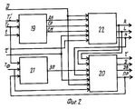
В состав блока анализа наличия и направления перекоса входят узел разрешения счета, узел поворота или движения, узел запрета поворота и узел определения наличия информации и направления поворота. The structure of the analysis of the presence and direction of bias includes an account resolution unit, a rotation or movement unit, a rotation prohibition unit, and a node for determining the availability of information and the direction of rotation.
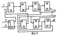
Узел разрешения счета состоит из пяти одновибраторов, двух схем совпадения и RS-триггера, вход установки которого соединен с выходом делителя, а вход сброса соединен с делителем частоты, а выход подключен ко входу первой схемы совпадения, к другим входам которой подключены выходы второй схемы совпадения и тактового генератора, а выход соединен со входом первого одновибратора, инверсный выход которого подключен ко входу второго одновибратора, прямой выход которого соединен со входом узла определения наличия информации и направления поворота, а инверсный выход подключен ко входу второй схемы совпадения и входу третьего одновибратора, выход которого подключен ко входу второй схемы совпадения и входу четвертого одновибратора, прямой выход которого подключен ко входу узла определения наличия информации направления поворота, а инверсный выход ко входу второй схемы совпадения и входу пятого одновибратора, инверсный выход которого соединен со входом второй схемы совпадения, а прямой выход - со входом узла определения наличия информации и направления поворота. The account resolution node consists of five single-vibrators, two coincidence circuits, and an RS trigger, the installation input of which is connected to the output of the divider, and the reset input is connected to the frequency divider, and the output is connected to the input of the first coincidence circuit, the outputs of the second coincidence circuit are connected to other inputs and a clock generator, and the output is connected to the input of the first one-shot, whose inverse output is connected to the input of the second one-shot, whose direct output is connected to the input of the node for determining the availability of information and direction of rotation and the inverse output is connected to the input of the second matching circuit and the input of the third one-shot, the output of which is connected to the input of the second matching circuit and the input of the fourth one-shot, the direct output of which is connected to the input of the node determining the presence of information of the direction of rotation, and the inverse output to the input of the second matching circuit and the input of the fifth one-shot, the inverse output of which is connected to the input of the second coincidence circuit, and the direct output to the input of the node for determining the availability of information and direction of rotation.
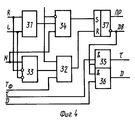
Узел поворота или движения состоит из двух элементов ИЛИ, четырех элементов И, и RS-триггера. Входы первой ИЛИ подключен к выходам узла определения наличия информации и направления поворота, а выход соединен со входом первого И, другие входы которого соединены с выходом узла запрета поворота и выходом узла определения наличия информации и направления поворота, а выход соединен с установочным входом RS-триггера, вход сброса которого соединен с выходом второго ИЛИ, инверсный выход которого соединен со входами третьего и четвертого И и входом узла разрешения поворота призмы, прямой выход - со входом узла запрета поворота и выходом узла разрешения перемещения носителя, входы второго И соединены с выходами узла определения наличия информации и направления поворота, а выход соединен со входом второго ИЛИ, другие входы которого соединены с выходом узла запрета поворота и сигналом начало фрагмента Тф. Входы третьего и четвертого И соединены с выходами счетно-решающего блока, а выходы являются выходами устройства.A rotation or motion node consists of two OR elements, four AND elements, and an RS trigger. The inputs of the first OR are connected to the outputs of the node for determining the availability of information and the direction of rotation, and the output is connected to the input of the first AND, the other inputs of which are connected to the output of the node for inhibiting rotation and the output of the node for determining the availability of information and direction of rotation, and the output is connected to the installation input of the RS-trigger , the reset input of which is connected to the output of the second OR, the inverse output of which is connected to the inputs of the third and fourth AND and the input of the node allowing the rotation of the prism, the direct output is with the input of the node of the prohibition of rotation and the output of the knots and permit movement of the carrier, and second inputs connected to the outputs determining the presence of node information and the direction of rotation, and an output connected to the input of a second OR, the other inputs of which are connected to the output node of rotation prohibition signal and the beginning of the frame T f. The inputs of the third and fourth AND are connected to the outputs of the computing unit, and the outputs are the outputs of the device.
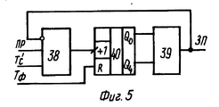
Узел запрета поворота состоит из двух элементов И и пятиразрядного двоичного счетчика. Вход первого И соединен с выходом узла поворота или движения, другие входы соединены с выходом делителя частоты и выходом второго И, а выход подключен к суммирующему входу счетчика, на вход сброса которого подается импульс начало фрагмента Тф, а выходы с нулевого и четвертого разрядов соединены со входами второго И, выход которого соединен со входом узла определения наличия информации и направления поворота, а также входом узла поворота или движения.The rotation prohibition node consists of two AND elements and a five-digit binary counter. The input of the first AND is connected to the output of the rotation or movement unit, the other inputs are connected to the output of the frequency divider and the output of the second And, and the output is connected to the summing input of the counter, the reset input of which is the beginning of the fragment T f , and the outputs from the zero and fourth digits are connected with the inputs of the second AND, the output of which is connected to the input of the node for determining the availability of information and the direction of rotation, as well as the input of the node of rotation or movement.
Узел определения наличия информации и направления поворота состоит из шести элементов И, трех элементов ИЛИ, двоичного реверсивного счетчика на восемь разрядов и трех RS-триггеров. Входы первого И соединены с выходами счетно-решающего блока, выходом узла разрешения счета и выходом делителя, а выход соединен с накапливающим входом счетчика, входы второго И соединены с выходами тех же узлов, а выход соединен с вычитающим входом счетчика, на вход сброса счетчика поступает импульс Тс ll, соответствующий переднему фронту импульса Тс, выходы Q3-Q7 соединены со входами третьего И и входами первого ИЛИ, выходы Q0-Q3 соединены со входами четвертого И и второго ИЛИ, другие входы которых соединены с выходами узла разрешения счета, выход третьего И соединен со входом пятого И, другие входы которого соединены с выходом узла разрешения счета, выходом заем счетчика и выходом третьего RS-триггера, входы третьего ИЛИ соединены с выходом четвертого И и инверсным выходом второго ИЛИ, а выход соединен с установочным входом третьего RS-триггера, установочный вход первого RS-триггера соединен с выходом пятого элемента И, установочный вход второго триггера соединен с выходом шестого элемента И, входы сброса триггеров соединены с сигналом Тс ll, а выходы всех трех триггеров соединены со входами узла поворота или движения, а выходы первого и второго триггеров соединены со входами узла разрешения поворота призмы.The node for determining the availability of information and direction of rotation consists of six AND elements, three OR elements, a binary eight-bit counter and three RS-flip-flops. The inputs of the first AND are connected to the outputs of the counting-decisive block, the output of the node for resolving the count and the output of the divider, and the output is connected to the accumulating input of the counter, the inputs of the second AND are connected to the outputs of the same nodes, and the output is connected to the subtracting input of the counter, the pulse T c ll corresponding to the leading edge of the pulse T c , the outputs Q 3 -Q 7 are connected to the inputs of the third AND and the inputs of the first OR, the outputs Q 0 -Q 3 are connected to the inputs of the fourth AND and the second OR, the other inputs of which are connected to the outputs of the node permission account a, the output of the third AND is connected to the input of the fifth AND, the other inputs of which are connected to the output of the account resolution unit, the output of the counter loan and the output of the third RS-trigger, the inputs of the third OR are connected to the output of the fourth AND and the inverse output of the second OR, and the output is connected to the installation input of the third RS-trigger input of the first installation RS-flip-flop connected to the output of the fifth aND gate, the second flip-adjusting input connected to the output of the sixth aND gate, the reset inputs of flip-flops connected to the signal T to ll, and the outputs of the three flip-flops Comm Nena to the inputs of a node of rotation or movement, and the outputs of the first and second flip-flops are connected to the inputs of the prism assembly permits rotation.
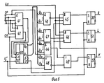
На фиг. 1 приведена общая структурная схема устройства; на фиг. 2 - структурная схема блока анализа наличия и направления перекоса; на фиг. 3 - схема узла разрешения счета; на фиг. 4 - схема узла поворота или движения; на фиг. 5 - схема узла запрета поворота; на фиг. 6 - схема узла определения наличия информации и направления поворота. In FIG. 1 shows a general block diagram of a device; in FIG. 2 is a block diagram of a block for analyzing the presence and direction of skew; in FIG. 3 is a diagram of an account resolution unit; in FIG. 4 is a diagram of a rotation or movement unit; in FIG. 5 is a diagram of a rotation inhibiting assembly; in FIG. 6 is a diagram of a node for determining the availability of information and direction of rotation.
В состав устройства входят тактовый генератор 1, делитель частоты 2, линейный фоточувствительный прибор с зарядовой связью 3, аналого-цифровой преобразователь 4, делитель частоты 5, блок управления 6, узел 7 привода углового перемещения, винтовая пара 8 источника света 9, носитель информации 10, объектив 11, счетно-решающий блок 12, поворотная призма 13, блок 14 анализа наличия и направления перекоса, и винтовая пара 15 привода углового перемещения призмы, узлы привода перемещения носителя 16 и разрешения углового поворота призмы, блок анализа наличия и направления перекоса 14. В состав блока анализа наличия и направления перекоса, входят: узел запрета поворота 17, узел определения наличия информации и направления поворота 18, узел разрешения счета 19, узел поворота или движения 20. The device includes a
Узел разрешения счета состоит из RS-триггера 23, двух схем совпадения 24, 25 и пяти стабильных одновибраторов 26, 27, 21, 22, 30. The account resolution node consists of an RS flip-
Узел поворота или движения состоит из двух схем ИЛИ 31, 32, четырех схем совпадения 33, 34, 29, 30 и RS-триггера 35. The rotation or movement unit consists of two
Узел запрета поворота состоит из двух схем совпадения 37, 35 и двоичного счетчика накапливающего типа 36 на пять двоичных разрядов. The rotation prohibition node consists of two
Узел определения наличия информации и направления поворота состоит из шести схем совпадения 41, 42, 43, 44, 45, 46, трех схем объединения 47, 48, 49, трех RS-триггеров 50, 51, 39 и двоичного восьмиразрядного реверсивного счетчика 40. The node for determining the availability of information and direction of rotation consists of six
Устройство считывания информации работает следующим образом. Импульсы начало строки Тс, начало рабочей строки Тс и тактовые импульсы t поступают на вход узла разрешения счета, в котором по импульсу Тс l устанавливается триггер 23, который разрешает выработку импульсов разрешения счета количества битов. поступающих с двух симметричных относительно центра строки участков. Импульс СР разрешает счет с первого участка, а импульс СМ - со второго. Кроме того, в узле вырабатывается импульс АН для разрешения анализа наличия перекоса. Указанные импульсы вырабатываются последовательно с помощью схем совпадения 24, 25 и стабильных одновибраторов 26, 27, 27, 21, 22 и имеют определенную длительность.The information reader works as follows. The pulses are the beginning of the line T s , the beginning of the working line T s and the clock pulses t are fed to the input of the count resolution node, in which the
Устранение перекоса осуществляется на нескольких первых информационных строках фрагмента, для остальных же строк фрагмента поворот призмы запрещен сигналом ЗП. Для выработки сигнала ЗП на узел запрета поворота подают сигнал ПР, указывающий на наличие перекоса носителя, и сигналы начало рабочей строки Тс l и начало фрагмента Тф. Последний сбрасывает счетчик 40, который служит для подсчета и ограничения числа попыток восстановления перекоса. Сигнал ЗП в начале фрагмента имеет низкий потенциал. При возникновении сигнала ПР (перекос) по каждому импульсу Тс l происходит прибавление единицы к содержимому счетчика 36 с помощью схемы И 38 и как только содержимое счетчика достигнет некоторой пороговой величины, то с помощью схемы совпадения 37 вырабатывается сигнал ЗП, одновременно запрещающий изменение счетчика до начала нового фрагмента.The skew is eliminated on the first few information lines of the fragment; for the remaining lines of the fragment, prism rotation is prohibited by the RF signal. To generate the RF signal, the PR signal is sent to the rotation prohibition node, indicating the presence of a skew of the carrier, and signals the beginning of the working line T with l and the beginning of the fragment T f . The latter resets counter 40, which serves to count and limit the number of attempts to restore skew. The RF signal at the beginning of the fragment has a low potential. When a PR signal (skew) occurs for each pulse T with l , the unit is added to the contents of the
Сигнал ЗП поступает на узел поворота или движения, на который также поступают сигналы R - правый поворот, L - левый поворот, N - наличие информации в строке, импульсы t с выхода тактового генератора, импульсы наличия информации в бите τи D. По низкому уровню ЗП и при наличии сигнала R или L, поступающего со схемы ИЛИ 31 на входы схемы И 34, а также высокого уровня N устанавливается триггер 35, что приводит к выработке сигнала ПР на разрешение поворота и одновременно появляется низкий уровень сигнала ДВ, запрещающий перемещение носителя и прохождение импульсов τи D с помощью схем И 29 и 30 на выход устройства. Сбрасывается триггер 35 импульсом Тф или ЗП, а также при отсутствии перекоса с помощью схемы И 33 и схемы ИЛИ 32. Инверсное состояние триггера 35 разрешает движение носителя и прохождение сигналов τи D на выход.The RF signal arrives at the rotation or motion node, which also receives the signals R — right turn, L — left turn, N — presence of information in the line, pulses t from the output of the clock generator, pulses of information in bit τ and D. At a low level of RF and if there is a signal R or L coming from the
На узел определения наличия информации и направления поворота подаются сигналы τ, D, СР, СМ, АН и Тс l и Тc ll. Наличие высокого уровня сигнала СР и низкого уровня сигнала СМ разрешает с помощью схемы И 41 накопление в счетчике 40 числа, соответствующего количеству информационных битов первого анализируемого участка строки, а наличие высокого уровня сигнала СМ при низком уровне СР разрешает с помощью схемы И 42 вычитание из счетчика 40 числа, соответствующего количеству информационных битов второго анализируемого участка строки. Счетчик 59 сбрасывается в начале каждой рабочей строки по сигналу Тс ll, соответствующему переднему фронту сигнала Тс l. Наличие информации в строке определяется по ненулевому состоянию счетчика 40 с помощью схемы совпадения 44 или с помощью схемы объединения 45, в результате чего устанавливается триггер 39, на выходе которого появляется высокий уровень сигнала N. Сигналы N, АН и отсутствие сигнала заема в счетчике 40 при наличии хотя бы одного нулевого значения выходов Q3-Q7 счетчика 53 вызывают с помощью схемы И 45 установку триггера 50 правого поворота (сигнал R), а наличие сигнала заема и хотя бы одного ненулевого значения выходов Q3-Q7 счетчика 40 вызывают с помощью схемы И 46 установку триггера 51 левого поворота (сигнал L). Сброс этих триггеров осуществляется в начале рабочей строки импульсов Тс ll.Signals τ, D, CP, SM, AN and T with l and T c ll are sent to the node for determining the availability of information and the direction of rotation. The presence of a high level of the CP signal and a low level of the signal SM allows the accumulation in the counter 40 of the number corresponding to the number of information bits of the first analyzed section of the line, and the presence of a high level of the signal SM with a low level of CP allows using the
Сигнал ПР разрешает поворот призмы с помощью узла 7, а сигнал ДВ разрешает движение носителя с помощью узлов 16. Если необходим поворот призмы, то направление поворота определяется сигналами R и L, поступающими на узел 7. The PR signal allows the prism to rotate using the node 7, and the DV signal allows the carrier to move with the help of the nodes 16. If the prism rotation is necessary, the direction of rotation is determined by the signals R and L, arriving at the node 7.
Claims (2)
Priority Applications (1)
| Application Number | Priority Date | Filing Date | Title |
|---|---|---|---|
| SU4929999 RU2024941C1 (en) | 1991-04-22 | 1991-04-22 | Device for reading data out from photocarrier |
Applications Claiming Priority (1)
| Application Number | Priority Date | Filing Date | Title |
|---|---|---|---|
| SU4929999 RU2024941C1 (en) | 1991-04-22 | 1991-04-22 | Device for reading data out from photocarrier |
Publications (1)
| Publication Number | Publication Date |
|---|---|
| RU2024941C1 true RU2024941C1 (en) | 1994-12-15 |
Family
ID=21571140
Family Applications (1)
| Application Number | Title | Priority Date | Filing Date |
|---|---|---|---|
| SU4929999 RU2024941C1 (en) | 1991-04-22 | 1991-04-22 | Device for reading data out from photocarrier |
Country Status (1)
| Country | Link |
|---|---|
| RU (1) | RU2024941C1 (en) |
Cited By (1)
| Publication number | Priority date | Publication date | Assignee | Title |
|---|---|---|---|---|
| RU2355005C1 (en) * | 2007-07-24 | 2009-05-10 | ООО Тульское производственное предприятие "Конус" | Device for circular scanning |
-
1991
- 1991-04-22 RU SU4929999 patent/RU2024941C1/en active
Non-Patent Citations (2)
| Title |
|---|
| 1. Плеханов В.М., Славинский З.М. Применение ПЗС для автоматизации сборки интегральных микросхем. Электронная промышленность. 1982, вып.7, с.86. * |
| 2. Авторское свидетельство СССР N 1538765, кл. G 06K 11/00, 1990. * |
Cited By (1)
| Publication number | Priority date | Publication date | Assignee | Title |
|---|---|---|---|---|
| RU2355005C1 (en) * | 2007-07-24 | 2009-05-10 | ООО Тульское производственное предприятие "Конус" | Device for circular scanning |
Similar Documents
| Publication | Publication Date | Title |
|---|---|---|
| EP0037830A4 (en) | Object and people counting system. | |
| RU2024941C1 (en) | Device for reading data out from photocarrier | |
| US3403261A (en) | Plural channel optical memory using light beam transit time to discriminate among channels | |
| SU1591189A1 (en) | Signal decoder | |
| EP0285662B1 (en) | Digital pulse circuit | |
| EP0363475A1 (en) | An improved target association method. | |
| SU1670805A1 (en) | Television direction finder | |
| SU1620970A1 (en) | Method and apparatus for automatic checking of focusing of images in optronic device | |
| SU1654852A1 (en) | Device for reading graphic information | |
| SU1619419A2 (en) | Photodetector of moving images | |
| SU1677877A1 (en) | Device for measuring distance between the centers of interference bands of interferogram | |
| RU2091708C1 (en) | Gear measuring linear and angular movements | |
| JP2561239B2 (en) | Automatic focus adjustment device | |
| SU1072072A1 (en) | Device for reading information from printed circuit boards | |
| SU1509993A1 (en) | Optical memory | |
| SU1215176A1 (en) | Shaft turn angle-to-digital converter | |
| SU1756910A1 (en) | Device for conversion of images | |
| SU570892A1 (en) | Information input device for digital computer | |
| SU752327A1 (en) | Binary number comparing device | |
| SU968832A1 (en) | Device for measuring linear displacement of an object | |
| SU1254408A1 (en) | Optronic device for automatic registering of defocusing level of lens | |
| SU1037346A1 (en) | Memory | |
| SU932486A1 (en) | Number comparing device | |
| SU606157A1 (en) | Arrangement for discriminating image edges on film with framewise information representation | |
| SU1080165A1 (en) | Information readout device |