RU2024938C1 - Device for square rooting of sum of three squared values - Google Patents
Device for square rooting of sum of three squared values Download PDFInfo
- Publication number
- RU2024938C1 RU2024938C1 SU5034966A RU2024938C1 RU 2024938 C1 RU2024938 C1 RU 2024938C1 SU 5034966 A SU5034966 A SU 5034966A RU 2024938 C1 RU2024938 C1 RU 2024938C1
- Authority
- RU
- Russia
- Prior art keywords
- input
- output
- inputs
- maximum
- amplitude selector
- Prior art date
Links
Images
Landscapes
- Measurement Of Current Or Voltage (AREA)
Abstract
Description
Изобретение относится к автоматике и вычислительной технике, а именно к устройствам извлечения квадратного корня из суммы квадратов трех величин, и может быть использовано в вычислительных устройствах для преобразования координат, определения суммарного вектора с высокой точностью. The invention relates to automation and computer technology, namely, devices for extracting the square root of the sum of the squares of three values, and can be used in computing devices to convert coordinates, determine the total vector with high accuracy.
Известно устройство для извлечения корня, содержащее три амплитудных модулятора, генератор синусоидальных напряжений, два сумматора, фазовращатель, ограничитель, детектор и фильтр. A device for extracting the root, containing three amplitude modulators, a sinusoidal voltage generator, two adders, phase shifter, limiter, detector and filter.
Устройство осуществляет сложение модулированных по амплитуде высокочастотных колебаний напряжений, сдвинутых по фазе относительно друг друга, и выделение огибающей суммарного сигнала. Устройство ограничено по быстродействию и точности измерений. The device performs the addition of amplitude-modulated high-frequency oscillations of voltages shifted in phase relative to each other, and the selection of the envelope of the total signal. The device is limited in speed and accuracy.
Известен функциональный преобразователь, содержащий операционный усилитель, три инвертора, блоки выделения модуля, каждый из которых выполнен на трех двухвходовых диодных элементах, и несколько резистивных звезд с четырьмя входами каждая. Устройство обладает высоким быстродействием, в нем нет сложных элементов, однако наличие большого количества диодов ограничивает точность измерений из-за падения в них напряжения. A functional converter is known that contains an operational amplifier, three inverters, module isolation blocks, each of which is made on three two-input diode elements, and several resistive stars with four inputs each. The device has high speed, it has no complex elements, however, the presence of a large number of diodes limits the accuracy of the measurements due to the voltage drop in them.
Наиболее близким техническим решением к заявляемому по большему количеству сходных существенных признаков и достигаемому эффекту является устройство для извлечения квадратного корня из суммы квадратов трех величин, содержащее три блока выделения модуля сигналов, подключенных входами к входам устройства с первого по третий, соответственно, три двухвходовых и один трехвходовый блоки вычисления максимума, входы которых подключены к выходам блоков выделения модулей, а выходы подключены к входам многовходового сумматора на операционном усилителе с резистивной обратной связью. The closest technical solution to the claimed one for a greater number of similar essential features and the achieved effect is a device for extracting the square root of the sum of squares of three values, containing three signal module isolation blocks connected to the device inputs from the first to the third, respectively, three two-input and one three-input maximum calculation blocks, the inputs of which are connected to the outputs of the modules selection blocks, and the outputs are connected to the inputs of the multi-input adder on the operating room amplifier with resistive feedback.
Устройство простое по конструкции и построено на принципе кусочно-линейной аппроксимации искомого выражения суммой из комбинации входных напряжений, которые в зависимости от их соотношений складывают с постоянными коэффициентами, задаваемыми соотношением сопротивлениями резистора обратной связи ОУ и сопротивлений его входных резисторов. The device is simple in design and is built on the principle of piecewise linear approximation of the desired expression by the sum of a combination of input voltages, which, depending on their ratios, are added with constant coefficients specified by the ratio of the resistors of the feedback resistor of the op-amp and the resistances of its input resistors.
Точность преобразования, определяемая точностью аппроксимации, ограничена, что обусловлено выбором семи постоянных коэффициентов независимо от величины входных напряжений. Методическая погрешность составляет около 4%. The conversion accuracy, determined by the approximation accuracy, is limited, due to the choice of seven constant coefficients, regardless of the magnitude of the input voltages. The methodological error is about 4%.
Целью изобретения является уменьшение погрешности преобразования. The aim of the invention is to reduce the conversion error.
Цель в устройстве для извлечения квадратного корня из суммы квадратов трех величин, содержащем три блока выделения модуля, подключенных входами к входам устройства с первого по третий, соответственно, и сумматор, выход которого является выходом устройства, достигается тем, что в него введены амплитудный селектор, два блока деления и два управляемых делителя напряжения, причем к первому входу сумматора подключен выход максимального сигнала амплитудного селектора, этот же выход подключен к первому входу первого блока деления и к первому входу второго блока деления, выход медианного сигнала амплитудного селектора подключен к второму входу первого блока деления и к сигнальному входу первого управляемого делителя, выход минимального сигнала амплитудного селектора подключен к второму входу второго блока деления и к сигнальному входу второго управляемого делителя напряжения, выход первого блока деления подключен к управляющему входу первого управляемого делителя напряжения, выход второго блока деления подключен к управляющему входу второго управляемого делителя напряжения, выход первого управляемого делителя напряжения подключен к второму сумматору, а выход второго управляемого делителя напряжения подключен к третьему входу сумматора, входы амплитудного селектора с первого по третий подключены к выходам блоков выделения модуля с первого по третий соответственно: амплитудный селектор содержит два трехвходовых блока вычисления максимума, три двухвходовых блока вычисления максимума и минимума и алгебраический сумматор, причем два входа первого двухвходового блока вычисления максимума и минимума подключены соответственно к первому и второму входам амплитудного селектора, два входа второго двухвходового блока вычисления максимума и минимума подключены соответственно к второму и третьему входам амплитудного селектора, два входа третьего двухвходового блока вычисления максимума и минимума подключены соответственно к второму и третьему входам амплитудного селектора, выходы максимальных сигналов двухвходовых блоков вычисления максимума и минимума подключены к входам первого трехвходового блока вычисления максимума, выходы минимальных сигналов двухвходовых блоков вычисления максимума и минимума подключены к входам второго трехвходового блока вычисления максимума, выход максимального сигнала амплитудного селектора подключен к выходу первого трехвходового блока вычисления максимума, выход медианного сигнала подключен к выходу второго трехвходового блока вычисления максимума, выход минимального сигнала подключен к выходу алгебраического сумматора, входы которого с первого по третий подключены к входам амплитудного селектора с первого по третий, соответственно к четвертому и пятому входам алгебраического сумматора подключены выходы первого и второго трехвходовых блоков вычисления максимума соответственно. The purpose of the device is to extract the square root of the sum of the squares of three values, containing three module selection blocks connected by inputs to the device inputs from the first to the third, respectively, and the adder, the output of which is the device output, is achieved by the fact that an amplitude selector is inserted into it, two dividing units and two controlled voltage dividers, and the output of the maximum signal of the amplitude selector is connected to the first input of the adder, the same output is connected to the first input of the first division unit and to the first the second division unit, the output of the median signal of the amplitude selector is connected to the second input of the first division unit and to the signal input of the first controlled divider, the output of the minimum signal of the amplitude selector is connected to the second input of the second division unit and to the signal input of the second controlled voltage divider, the output of the first division unit connected to the control input of the first controlled voltage divider, the output of the second division unit is connected to the control input of the second controlled voltage divider In this case, the output of the first controlled voltage divider is connected to the second adder, and the output of the second controlled voltage divider is connected to the third input of the adder, the inputs of the amplitude selector from the first to third are connected to the outputs of the module selection blocks from the first to the third, respectively: the amplitude selector contains two three-input calculation blocks maximum, three two-input blocks for computing maximum and minimum and an algebraic adder, with two inputs of the first two-input block for computing maximum and minimum n are connected respectively to the first and second inputs of the amplitude selector, two inputs of the second two-input unit for calculating the maximum and minimum are connected respectively to the second and third inputs of the amplitude selector, two inputs of the third two-input unit for calculating the maximum and minimum are respectively connected to the second and third inputs of the amplitude selector, the outputs of the maximum signals of two-input maximum and minimum calculation blocks are connected to the inputs of the first three-input maximum calculation block, min outputs of the two-input maximum and minimum calculation signal signals are connected to the inputs of the second three-input maximum calculation block, the output of the maximum amplitude selector signal is connected to the output of the first three-input maximum calculation block, the median signal output is connected to the output of the second three-input maximum calculation block, the minimum signal output is connected to the algebraic output the adder, the inputs of which from first to third are connected to the inputs of the amplitude selector from first to third, respectively The outputs of the first and second three-input maximum calculation blocks, respectively, are connected to the fourth and fifth inputs of the algebraic adder.
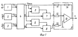
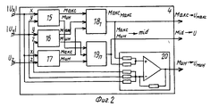
На фиг.1 показана функциональная схема устройства; на фиг.2 - амплитудный селектор. Figure 1 shows a functional diagram of the device; figure 2 - amplitude selector.
Устройство для извлечения квадратного корня из суммы квадратов трех величин содержит: блоки 1, 2, 3 выделения модуля; амплитудный селектор 4; блоки деления 5 и 6; управляемые делители напряжения 7 и 8; сумматор 9. A device for extracting the square root of the sum of the squares of three values contains:
Блоки в устройстве соединены следующим образом. Входы блоков 1-3 выделения модулей с первого по третий подключены к входам устройства с первого по третий соответственно. Выходы блоков 1-3 выделения модулей с первого по третий подключены к входам амплитудного селектора 4 с первого по третий соответственно. Первый выход амплитудного селектора 4 по сигналу максимальной амплитуды подключен к первому входу сумматора 9 и к первым входам блоков деления 5 и 6. Второй выход амплитудного селектора 4 по сигналу медианной амплитуды подключен к второму входу блока деления 5 и через управляемый делитель напряжения 7 подключен к второму входу сумматора 9. Третий выход амплитудного селектора 4 по сигналу минимальной амплитуды подключен к второму входу блока деления 6 и через второй управляемый делитель напряжения 8 подключен к третьему входу сумматора 9, выход которого подключен к входу устройства. Выходы блоков деления 5 и 6 подключены к управляющим входам управляемых делителей напряжения 7 и 8, соответственно. The blocks in the device are connected as follows. The inputs of blocks 1-3 of the allocation of modules from the first to the third are connected to the inputs of the device from the first to the third, respectively. The outputs of blocks 1-3 of the allocation of modules from the first to the third are connected to the inputs of the
Амплитудный селектор 4 (фиг.2) содержит три двухвходовых блока 15, 16, 17 вычисления максимума и минимума, два трехвходовых блока 18, 19 вычисления максимума и алгебраический сумматор 20. Блоки в амплитудном селекторе 4 соединены между собой следующим образом. Два входа блока 15 подключены соответственно к первому и второму входам (x,y) амплитудного селектора 4, два входа блока 16 подключены соответственно к второму и третьему входам (y, z) амплитудного селектора 4, два входа блока 17 подключены соответственно к первому и третьему входам (x,z) амплитудного селектора 4. Три выхода максимального сигнала блоков 15, 16, 17 подключены к трем входам блока вычисления максимума 18, а три выхода минимального сигнала блоков 15, 16, 17 подключены к трем входам блока вычисления максимума 19. К трем выходам амплитудного селектора 4 подключены к первому выходу (макс) подключен выход блока вычисления максимального сигнала блока 18; к второму выходу (mid) подключен выход блока вычисления максимума блока 19; к третьему выходу (мин) подключен выход алгебраического сумматора. The amplitude selector 4 (Fig. 2) contains three two-
Устройство работает следующим образом. На входы устройства поступают входные сигналы напряжения Ux,Uy,Uz . Эти сигналы каждый поступает на свой блок выделения модуля 1, 2, 3, с выхода которых получают сигналы I Ux I, I Uy I, I Uz I . Эти сигналы поступают на три входа амплитудного селектора 4, с первого выхода которого снимают сигналы максимальной амплитуды Uмакс ,со второго - сигнал среднего значения амплитуды U, с третьего - сигнал минимальной амплитуды Uмин, причем Uмин < U <макс.
Сигналы Uмакс и U с первого и второго выходов амплитудного селектора 4 поступают на первый и второй входы блока деления 5, а сигналы Uмакс и Uмин с первого и третьего выходов амплитудного селектора 4 поступают на первый и второй входы блока деления 6. С выхода блока деления 5 снимают напряжение, пропорциональное K1 = =Uмакс/U, а с выхода блока деления 6 снимают напряжение, пропорциональное K2 = =Uмакс/Uмин. Эти напряжения поступают на управляющие входы управляемых делителей напряжения 7 и 8 соответственно, а на их сигнальные входы поступают сигналы U и Uмин соответственно. С выходов управляемых делителей напряжения 7 и 8 снимают напряжения U/K1 и Uмин/К2 соответственно. С первого выхода амплитудного селектора 4 напряжение Uмакс поступает на первый вход сумматора 9, с выхода управляемого делителя напряжения 7 напряжение U/K1 поступает на второй вход сумматора 9, а на его третий вход поступает напряжение Uмин/K2 с выхода управляемого делителя напряжения 8.The device operates as follows. The inputs of the device receive input voltage signals U x , U y , U z . Each signal is fed to its own
The signals U max and U from the first and second outputs of the
Амплитудный селектор 4 формирует их входных напряжений I Ux I, I Uy I, I Uz I три выходных напряжения Uмакс, Umid, Uмин следующим образом. Для простоты обозначены сигналы, поступающие на вход амплитудного селектора 4, (x = Ux, y = Uy, z = Uz). На двухвходовые блоки вычисления максимума далее макс и минимума далее мин 15, 16, 17 поступают попарно сигналы: x, y; y,z; x, z - соответственно. С выходов этих блоков снимают сигналы двух типов из каждой пары входных сигналов - макс и мин. Все сигналы макс поступают на три входа первого трехвходового блока вычисления максимума 18, а все сигналы мин поступают на три входа второго трехвходового блока вычисления максимума 19. С выходов этих блоков снимают сигнал максимальный из трех входных сигналов, но с выхода блока 18 снимают максимальный сигнал из максимальных, а с выхода блока 19 снимают максимальный сигнал из минимальных, соответствующий среднему по величине выходному сигналу mid из трех входных сигналов амплитудного селектора 4. Сигналы Uмакс и Umidпоступает на первый и второй выходы амплитудного селектора 4. Алгебраический сумматор 20 вычитает из суммы сигналов Uмакс, Umid, Uминсигналы напряжений Uмакс, Umid, и на выходе алгебраического сумматора получают сигнал напряжения Uмин, который поступает на третий выход амплитудного селектора 4.The
На выходе сумматора 9 формируется напряжение
Uвых = Ко(Uмакс + aU/K1 + bUмин/K2, где коэффициенты Ко, а, b определяются соотношением сопротивлений резисторов сумматора 9:
Ko = R14/R11, Koa = R14/R12, Kob = =R14/R13.The output of the adder 9 is formed voltage
U out = K o (U max + aU / K 1 + bU m / K 2, where the coefficients Ko and, b are determined by resistors ratio combiner 9:
K o = R 14 / R 11 , K o a = R 14 / R 12 , K o b = = R 14 / R 13 .
Коэффициенты могут быть подобраны таким образом, чтобы с минимальной погрешностью обеспечить равенство двух выражений:
![]()
По исходному условию Uz < Uu < Ux, K1 = Ux/Uy, K2 = Ux/Uz, K1<K2.The coefficients can be selected in such a way as to ensure the equality of two expressions with a minimum error:
![]()
By the initial condition, Uz <Uu <Ux, K 1 = Ux / Uy, K 2 = Ux / Uz, K 1 <K 2 .
Для простоты рассуждений положим Ко = 1 (учтем это упрощение в дальнейшем). Выражение (1) можно представить в следующем виде:
Uz· ![]()
В выражении (2) Uz можно сократить, тогда равенство (1) будет выполняться при равенстве:
![]()
Следовательно, нужно выбрать такие значения коэффициентов а и b, чтобы погрешность выражения (1) была минимальна.For simplicity of reasoning, we put K o = 1 (we take this simplification into account later). Expression (1) can be represented as follows:
U z ![]()
In the expression (2) Uz can be reduced, then equality (1) will be fulfilled if:
![]()
Therefore, it is necessary to choose such values of the coefficients a and b so that the error of expression (1) is minimal.
Предположим, что Uz намного меньше двух других напряжений, тогда выражение (1) упрощается и сводится к выражению:
![]()
![]()
Из выражения (4) определим коэффициент а, приняв K1 = 1:
a=K1(![]()
![]()
![]()
From the expression (4) we determine the coefficient a, taking K 1 = 1:
a = K 1 ( ![]()
Погрешность а1 при выполнении равенства (4) будет равна:
q1= {[K1+0,4142/K1]/[![]()
Из выражения (5) определим значение коэффициента К1, при котором погрешность а1 будет иметь экстремальное значение. Для этого определим выражение для производной (q1) и, приравняв ее к нулю, определим К1( q1макс), как 0,4142/(1-0,8284) = 1,5536.The error a 1 when equality (4) is satisfied will be equal to:
q 1 = {[K 1 + 0.4142 / K 1 ] / [ ![]()
From expression (5) we determine the value of the coefficient K 1 at which the error a1 will have an extreme value. To do this, we define the expression for the derivative (q 1 ) and, equating it to zero, we define K 1 (q 1max ) as 0.4142 / (1-0.8284) = 1.5536.
Этому значению К1 будет соответствовать величина экстремальной погрешности, равная Iq1 I макс = -1,48%.This value of K 1 will correspond to the value of the extreme error equal to Iq1 I max = -1.48%.
Подставим а = 0,4142 в выражение (3) и, положив К1 = К2 = 1 определим величину коэффициента b. Коэффициент b = 0,31785.We substitute a = 0.4142 into expression (3) and, setting K 1 = K 2 = 1, we determine the value of coefficient b. Coefficient b = 0.31785.
Таким образом, при К1 = К2 = 1 и выбранных коэффициентах, погрешность равенства выражения (1) будет равна нулю. Оценим величину погрешности при других возможных значениях коэффициентов К1 и К2.Thus, when K 1 = K 2 = 1 and the selected coefficients, the equality of expression (1) will be equal to zero. We estimate the magnitude of the error at other possible values of the coefficients K 1 and K 2 .
При К2>>K1 коэффициент b оказывает минимальное влияние на результат измерений, что видно из выражения (1), а величина погрешности в этом случае, как было показано, не превышает значение - 1,48%. Определим, при каком значении отношения К2/К1 погрешность измерения будет иметь эстремальное значение.When K 2 >> K 1, the coefficient b has a minimal effect on the measurement result, which can be seen from expression (1), and the error in this case, as shown, does not exceed the value of 1.48%. We determine at what value of the ratio K 2 / K 1 the measurement error will have an extremal value.
Из выражения (3) определим погрешность измерения q2:
q2= {[(K2+ 0,4142K2)/K![]()
Домножим числитель и знаменатель в выражении для q2 на К2 и, обозначив (К2/K1)2 = =С, продифференцируем функцию q2 по С и приравняем ее нулю. После преобразований получим:
0,4142(К2 2 + С + 1) - 0,5(К2 2 + 0,4142С + +0,3178) = 0
Откуда получим:
С = 0,4142 К2 2 - 1,2326 (7)
Как видно из (7) область существования экстремумов зависит от значения коэффициента К2. Определим из (7) значение К2 для минимального значения Смин = 1, получим К2 = 2,32. Подставим его в выражение для ошибки (6) и получим q2 = -3%. С увеличением К2/К1 коэффициент К2 будет увеличиваться, а погрешность q2 будет уменьшаться, что видно (6), до величины q2 = -1,48%.From the expression (3) we determine the measurement error q 2 :
q 2 = {[(K 2 + 0.4142K 2 ) / ![]()
We multiply the numerator and denominator in the expression for q 2 by K 2 and, denoting (K 2 / K 1 ) 2 = = C, we differentiate the function q 2 with respect to C and equate it to zero. After the transformations we get:
0.4142 (K 2 2 + C + 1) - 0.5 (K 2 2 + 0.4142C + +0.3178) = 0
Where do we get:
C = 0.4142 K 2 2 - 1.2326 (7)
As can be seen from (7), the region of existence of the extrema depends on the value of the coefficient K 2 . We determine from (7) the value of K 2 for the minimum value of C min = 1, we obtain K 2 = 2,32. Substitute it into the expression for error (6) and get q 2 = -3%. With an increase in K 2 / K 1, the coefficient K 2 will increase, and the error q 2 will decrease, as can be seen (6), to q 2 = -1.48%.
Определим значение методической ошибки q2 в окрестности значений К1= 1,55, соответствующих экстремуму q1. Получим:
Если К1 = К2 = 1,55, то q2 = -3,58%
Если К1 = К2 = 1,5, то q2 = -3,57%
Если К1 = К2 = 1,6, то q2 = -3,65%
Если К1 = К2 = 1,7, то q2 = -3,64%.We determine the value of the methodological error q 2 in the vicinity of the values of K 1 = 1.55, corresponding to the extremum q 1 . We get:
If K 1 = K 2 = 1.55, then q 2 = -3.58%
If K 1 = K 2 = 1.5, then q 2 = -3.57%
If K 1 = K 2 = 1.6, then q 2 = -3.65%
If K 1 = K 2 = 1.7, then q 2 = -3.64%.
Как видно из проведенного анализа значений погрешностей, q2 имеет экстремальное значение около -3,65%. Это означает, что напряжение Uвыхна выходе сумматора 9 будет получаться меньше истинного значения максимально в 1,038 раза. Чтобы получить методическую погрешность измерений в 2 раза меньше, т. е. около 1,9%, следует увеличить выходное напряжение устройства в 1,019 раза, чему и должен быть равен коэффициент Ко выражения (1). Такая коррекция выходного напряжения осуществляется с помощью выбора резисторов сумматора 9:
Ko=R14/R11=1,019;
Ko a=R14/R12=0,422;
Ko b=R14/R13=0,324.As can be seen from the analysis of the error values, q 2 has an extreme value of about -3.65%. This means that the voltage U o at the output of the adder 9 will be less than the true value by a maximum of 1.038 times. To get the
K o = R 14 / R 11 = 1.019;
K o a = R 14 / R 12 = 0.422;
K o b = R 14 / R 13 = 0.324.
В этом устройстве для извлечения квадратного корня из суммы квадратов трех величин методическая ошибка вычисления равна 1,9% , что в 2 раза меньше, чем у прототипа. In this device for extracting the square root of the sum of the squares of three quantities, the methodological calculation error is 1.9%, which is 2 times less than that of the prototype.
Заявленное устройство имеет более широкие функциональные возможности по сравнению с известными аналогичными устройствами, так как позволяет определять отношение искомых сигналов, которое является одним из важных параметров при исследовании входных сигналов. The claimed device has wider functionality compared to known similar devices, as it allows you to determine the ratio of the desired signals, which is one of the important parameters in the study of input signals.
Claims (2)
Priority Applications (1)
| Application Number | Priority Date | Filing Date | Title |
|---|---|---|---|
| SU5034966 RU2024938C1 (en) | 1992-03-31 | 1992-03-31 | Device for square rooting of sum of three squared values |
Applications Claiming Priority (1)
| Application Number | Priority Date | Filing Date | Title |
|---|---|---|---|
| SU5034966 RU2024938C1 (en) | 1992-03-31 | 1992-03-31 | Device for square rooting of sum of three squared values |
Publications (1)
| Publication Number | Publication Date |
|---|---|
| RU2024938C1 true RU2024938C1 (en) | 1994-12-15 |
Family
ID=21600659
Family Applications (1)
| Application Number | Title | Priority Date | Filing Date |
|---|---|---|---|
| SU5034966 RU2024938C1 (en) | 1992-03-31 | 1992-03-31 | Device for square rooting of sum of three squared values |
Country Status (1)
| Country | Link |
|---|---|
| RU (1) | RU2024938C1 (en) |
-
1992
- 1992-03-31 RU SU5034966 patent/RU2024938C1/en active
Non-Patent Citations (3)
| Title |
|---|
| Авторское свидетельство СССР N 309370, кл G 06g 7/20, 1971. * |
| Авторское свидетельство СССР N 503255, кл. G 06G 7/20, 1976. * |
| Авторское свидетельство СССР N 744633, кл. G 06G 7/20, 1980. * |
Similar Documents
| Publication | Publication Date | Title |
|---|---|---|
| US4796993A (en) | Phase modulation type fiber optic gyroscope | |
| RU2024938C1 (en) | Device for square rooting of sum of three squared values | |
| RU2059289C1 (en) | Device for calculation of square root of sum of squares of three values | |
| RU2058587C1 (en) | Device for calculation of square root of sum of n values | |
| RU2022284C1 (en) | Method of determination of complex parameters of shf devices | |
| RU2007736C1 (en) | Device for determination of phase shift between two sine signals | |
| RU2037833C1 (en) | Device for measuring phase shifts of signals with known amplitude relations | |
| RU2045777C1 (en) | Device for extracting square root from sum of squares of two quantities | |
| US5278552A (en) | Indicator control circuit | |
| RU2047218C1 (en) | Device for square root extraction from sum of known and square of unknown values | |
| RU2058588C1 (en) | Trigonometric secant function generator | |
| RU2085995C1 (en) | Device for conversion of rectangular coordinates to polar ones | |
| SU1626194A1 (en) | Device for measuring complex reflection coefficient of microwave two-terminal network | |
| RU2057367C1 (en) | Arctangent function generator | |
| RU2060549C1 (en) | Device for calculation of trigonometric functions | |
| RU2025774C1 (en) | Apparatus for extraction of square root from product of two values | |
| RU2053554C1 (en) | Multifunctional trigonometric function generator | |
| RU2060543C1 (en) | Device for calculation of square root from sum of squares of two values | |
| RU2060544C1 (en) | Device for calculation of square root | |
| RU2037201C1 (en) | Device for calculating square root of sum of squares of two values | |
| US3480770A (en) | Apparatus for generating an angle-representative voltage | |
| RU2058044C1 (en) | Exponent function generator | |
| RU2060548C1 (en) | Device for calculation of reverse trigonometric functions arcsin x and arccos x | |
| RU1817033C (en) | Active power meter | |
| RU2117300C1 (en) | Device for measuring kinematic movement characteristics |