RU2024928C1 - Computer - Google Patents
Computer Download PDFInfo
- Publication number
- RU2024928C1 RU2024928C1 SU4886577A RU2024928C1 RU 2024928 C1 RU2024928 C1 RU 2024928C1 SU 4886577 A SU4886577 A SU 4886577A RU 2024928 C1 RU2024928 C1 RU 2024928C1
- Authority
- RU
- Russia
- Prior art keywords
- output
- input
- memory
- controller
- inputs
- Prior art date
Links
- 230000015654 memory Effects 0.000 claims abstract description 99
- 238000012790 confirmation Methods 0.000 claims description 9
- 238000009434 installation Methods 0.000 claims description 8
- 239000000126 substance Substances 0.000 abstract 1
- 230000003936 working memory Effects 0.000 abstract 1
- 239000011159 matrix material Substances 0.000 description 5
- 230000000903 blocking effect Effects 0.000 description 3
- 230000008859 change Effects 0.000 description 3
- 230000004913 activation Effects 0.000 description 2
- 230000005540 biological transmission Effects 0.000 description 2
- 238000010586 diagram Methods 0.000 description 2
- 238000000034 method Methods 0.000 description 2
- 230000008569 process Effects 0.000 description 2
- 230000008929 regeneration Effects 0.000 description 2
- 238000011069 regeneration method Methods 0.000 description 2
- 238000012546 transfer Methods 0.000 description 2
- RRLHMJHRFMHVNM-BQVXCWBNSA-N [(2s,3r,6r)-6-[5-[5-hydroxy-3-(4-hydroxyphenyl)-4-oxochromen-7-yl]oxypentoxy]-2-methyl-3,6-dihydro-2h-pyran-3-yl] acetate Chemical compound C1=C[C@@H](OC(C)=O)[C@H](C)O[C@H]1OCCCCCOC1=CC(O)=C2C(=O)C(C=3C=CC(O)=CC=3)=COC2=C1 RRLHMJHRFMHVNM-BQVXCWBNSA-N 0.000 description 1
- 230000003213 activating effect Effects 0.000 description 1
- 230000015572 biosynthetic process Effects 0.000 description 1
- 239000000872 buffer Substances 0.000 description 1
- 238000006243 chemical reaction Methods 0.000 description 1
- 238000011161 development Methods 0.000 description 1
- 230000018109 developmental process Effects 0.000 description 1
- 238000010894 electron beam technology Methods 0.000 description 1
- 238000005516 engineering process Methods 0.000 description 1
- 230000006870 function Effects 0.000 description 1
- 230000007246 mechanism Effects 0.000 description 1
- 230000008520 organization Effects 0.000 description 1
- 238000012545 processing Methods 0.000 description 1
Images


Landscapes
- Controls And Circuits For Display Device (AREA)
Abstract
Description
Изобретение относится к вычислительной технике и может быть использовано при разработке персональных бытовых ЭВМ, игровых автоматов и других средств вычислительной техники, построенных на основе микропроцессоров и осуществляющих индикацию информации на телевизионном мониторе или приемнике. The invention relates to computer technology and can be used in the development of personal household computers, gaming machines and other computer equipment based on microprocessors and displaying information on a television monitor or receiver.
Известны два основных способа представления в памяти ЭВМ изображений, выводимых на электронно-лучевую трубку: символьный и графический. В первом случае в видеопамяти хранятся коды отображаемых символов или элементов графики в последовательности, определяемой текстом. При стандартном формате экрана (25 строк по 80 символов) объем видеопамяти составляет 2000 байт. При отображении информации коды символов преобразуются в их изображения с помощью знакогенератора. Во втором случае в видеопамяти хранятся все элементы (точки, пикселы), составляющие изображение. При этом изображение может иметь произвольный вид (единственное ограничение - разрешающая способность), но объем видеопамяти резко увеличивается. В частности, для получения того же формата экрана, что и в рассмотренном случае, объем видеопамяти должен составлять не менее 12000 байт (при отображении символа матрицей 6х8 точек). There are two main ways of representing in computer memory images displayed on a cathode ray tube: symbolic and graphic. In the first case, the codes of displayed symbols or graphic elements are stored in the video memory in the sequence determined by the text. With a standard screen format (25 lines of 80 characters), the amount of video memory is 2000 bytes. When displaying information, character codes are converted into their images using a character generator. In the second case, all elements (points, pixels) that make up the image are stored in the video memory. In this case, the image may have an arbitrary appearance (the only limitation is the resolution), but the amount of video memory increases sharply. In particular, to obtain the same screen format as in the case under consideration, the amount of video memory should be at least 12,000 bytes (when displaying a symbol with a 6x8 pixel matrix).
Известен ряд ПЭВМ, для которых характерно высокое качество изображений, выводимых не видеомонитор, и большая гибкость преобразования этих изображений. В то же время обладают следующими недостатками: большим объемом видеопамяти и высокими требованиями к быстродействию микропроцессора, формирующего изображения в памяти. По этим причинам в большинстве таких ЭВМ видеопамять вынесена из основной памяти (это позволяет видеоконтроллеру функционировать параллельно основному процессору, благодаря чему повышается производительность последнего) и либо используется мощный микропроцессор (как правило 16-разрядный), обладающий командами, обрабатывающими строки данных, либо видеоконтроллер, обладающий способностью автономно осуществлять достаточно простое преобразование информации (например, сдвиг) в видеопамяти. A number of PCs are known for which a high quality of images displayed by a non-video monitor is characteristic, and a great flexibility in converting these images. At the same time, they have the following disadvantages: a large amount of video memory and high requirements for the speed of a microprocessor that forms images in memory. For these reasons, in most of these computers, the video memory is removed from the main memory (this allows the video controller to function in parallel with the main processor, which increases the performance of the latter) and either a powerful microprocessor (usually 16-bit) with commands that process data strings or a video controller is used. with the ability to autonomously carry out a fairly simple conversion of information (for example, shift) in video memory.
Недостатком микроЭВМ-прототипа является отсутствие возможности плавного перемещения изображения на экране видеомонитора. Действительно, изображение на экране зависит только от того, какие коды записаны в видеопамяти. Для перемещения изображения, например, вверх на строку следует сдвинуть информацию в видеопамяти вперед на число символов, отображаемых в строке текста на экране. Однако, очевидно, что изображение при этом изменится скачком, сразу сместившись на целую строку символов. Никаких промежуточных стадий не будет. The disadvantage of the microcomputer prototype is the lack of the ability to smoothly move the image on the screen of the video monitor. Indeed, the image on the screen depends only on which codes are recorded in the video memory. To move an image, for example, up a line, you should move the information in the video memory forward by the number of characters displayed in the line of text on the screen. However, it is obvious that the image will change abruptly, immediately shifting to a whole line of characters. There will be no intermediate stages.
Целью настоящего изобретения является расширение функциональных возможностей микроЭВМ с символьным способом представления информации в видеопамяти за счет устранения указанного недостатка. The aim of the present invention is to expand the functionality of microcomputers with a symbolic way of representing information in video memory by eliminating this drawback.
Существенным отличием предлагаемой микроЭВМ, содержащей микропроцессор, контроллер прямого доступа к памяти, контроллер видеотерминала, узел ввода-вывода, блок оперативной памяти, блок постоянной памяти, дешифратор, генератор синхросигналов, запоминающий узел знакогенератора, формирователь видеосигнала, элемент ИЛИ, причем адресные выходы микропроцессора соединены с адресными входами блоков оперативной и постоянной памяти, с информационными входами дешифратора и с адресными входами-выходами контроллера прямого доступа к памяти "группа младших выходов адреса микропроцессора связана с адресными входами контроллера видеотерминала, информационные входы-выходы микропроцессора соединены с информационными входами-выходами контроллеров видеотерминала, прямого доступа к памяти и узла ввода-вывода, с информационными входами блока оперативной памяти и информационными выходами блоков оперативной и постоянной памяти, управляющий выход чтения памяти микропроцессора соединен с одноименным выходом контроллера прямого доступа к памяти и со входом контроллера прямого доступа к памяти и со входом чтения блока постоянной памяти. Управляющий выход записи в память микропроцессора соединен с одноименным выходом контроллера прямого доступа к памяти и с входом записи блока оперативной памяти, управляющие выходы чтения и записи устройств ввода-вывода микропроцессора соединены соответственно с одноименными входами-выходами контроллера прямого доступа к памяти, а также входами узла ввода-вывода и контроллера видеотерминала, выход подтверждения прямого доступа микропроцессора связан с одноименным входом контроллера прямого доступа к памяти, выход запроса прямого доступа которого подключен к одноименному входу микропроцессора, входы начальной установки микропроцессора и контроллера прямого доступа к памяти связаны между собой и подключены к входу начальной установки микроЭВМ, выход разрешения адреса контроллера прямого доступа к памяти соединен с управляющим входом дешифратора, первые четыре выхода которого подключены соответственно к входам обращения контроллеров прямого доступа к памяти и видеотерминала, блоков оперативной и постоянной памяти, а группа выходов связана с группой управляющих входов узла ввода-вывода, выход подтверждения прямого доступа к памяти контроллера прямого доступа к памяти соединен с одноименным входом контроллера видеотерминала, а выход запроса прямого доступа к памяти последнего связан с одноименным входом контроллера прямого доступа к памяти, один из выходов генератора синхросигналов подключен к тактовым входам микропроцессора и контроллера прямого доступа к памяти, второй выход генератора связан с тактовым входом формирователя видеосигнала, выход синхронизации которого соединен со входом символьной синхронизации контроллера видеотерминала, выходы кода символа и номера строки растра контроллера подключены соответственно к группам старших и младших адресных входов запоминающего узла знакогенератора, выходы последнего связаны соответственно с информационными входами формирователя видеосигнала, выход видеосигнала которого подключен к одному из входов элемента ИЛИ, соединенного выходом с выходом видеосигнала микроЭВМ, выход горизонтальной синхронизации контроллера видеотерминала подключен ко второму входу элемента ИЛИ и выходу горизонтальной синхронизации видеотерминала микроЭВМ, является введение регистра, счетчика-регистра, логического узла и трех одновибраторов, причем информационные входы регистра связаны соответственно с упомянутыми информационными входами-выходами микропроцессора, вход записи регистра подключен к пятому выходу дешифратора, а выходы регистра соединены соответственно с информационными входами счетчика-регистра, вход занесения которого связан с выходом вертикальной синхронизации контроллера видеотерминала, выходы подключены к информационным входам логического узла, связанного тактовым входом с выходом горизонтальной синхронизации контроллера видеотерминала, первым выходом подключенного к счетному входу счетчика-регистра, а вторым выходом соединенного со входами первого и второго одновибраторов, выход первого одновибратора через третий одновибратор подключен к третьему входу элемента ИЛИ, а выход второго одновибратора связан с выходом вертикальной синхронизации видеотерминала микроЭВМ. A significant difference of the proposed microcomputer containing a microprocessor, a direct memory access controller, a video terminal controller, an input / output unit, a random access memory unit, a read-only memory unit, a decoder, a clock generator, a memory generator unit, a video signal conditioner, an OR element, and the microprocessor address outputs are connected with address inputs of RAM and read-only memory blocks, with information inputs of a decoder and with address inputs-outputs of a direct memory access controller "gr ppa of the junior outputs of the microprocessor address is connected to the address inputs of the video terminal controller, the information inputs and outputs of the microprocessor are connected to the information inputs and outputs of the video terminal controllers, direct access to the memory and the input / output node, with the information inputs of the random access memory block and the information outputs of the random and permanent memory blocks , the microprocessor memory read control output is connected to the direct-access memory controller output of the same name and to the direct-access controller input upa to memory and with a read input of a read-only memory block. The microprocessor memory control output is connected to the direct-access memory controller output of the same name and the RAM block record input; microprocessor control read and write control outputs are connected to the inputs and outputs of the direct memory access controller, as well as node inputs, respectively input / output and video terminal controller, microprocessor direct access confirmation output is connected to the direct memory access controller input of the same name, direct request the access of which is connected to the microprocessor input of the same name, the inputs of the initial installation of the microprocessor and the controller of direct access to memory are interconnected and connected to the input of the initial installation of the microcomputer, the output of the address resolution of the controller of direct access to memory is connected to the control input of the decoder, the first four outputs of which are connected respectively to the access inputs of the direct access controllers to the memory and the video terminal, the blocks of RAM and read-only memory, and the group of outputs is connected to the group of control x inputs of the I / O node, the direct memory access confirmation output of the direct memory access controller is connected to the input of the video terminal controller of the same name, and the output of the direct memory access request of the latter is connected to the input of the direct memory access controller of the same name, one of the outputs of the clock generator is connected to the clock inputs of the microprocessor and the direct memory access controller, the second output of the generator is connected to the clock input of the video driver, the synchronization output of which is connected to the input arbitrary synchronization of the video terminal controller, the outputs of the symbol code and line numbers of the raster of the controller are connected respectively to the groups of senior and junior address inputs of the memory node of the character generator, the outputs of the latter are connected respectively to the information inputs of the video signal generator, the video signal output of which is connected to one of the inputs of the OR element connected to the output with the microcomputer video signal output, the horizontal synchronization output of the video terminal controller is connected to the second input of the element LI and the horizontal synchronization output of the video terminal of the microcomputer, is the introduction of a register, a counter-register, a logical node and three single-vibrators, moreover, the information inputs of the register are connected respectively to the information inputs-outputs of the microprocessor, the input of the register is connected to the fifth output of the decoder, and the outputs of the register are connected, respectively with information inputs of the counter-register, the input of which is connected to the output of the vertical synchronization of the video terminal controller, the outputs are sub are connected to the information inputs of the logical node connected by the clock input with the horizontal synchronization output of the video terminal controller, the first output connected to the counting input of the counter-register, and the second output connected to the inputs of the first and second one-shots, the output of the first one-shot through the third one-shot is connected to the third input of the OR element and the output of the second one-shot is connected with the output of the vertical synchronization of the video terminal of the microcomputer.
На фиг.1, 2 приведена схема предлагаемой микроЭВМ. Она содержит микропроцессор 1, контроллер 2 прямого доступа к памяти (ПДП), контроллер 3 видеотерминала (ВТ), узел 4 ввода-вывода, блок 5 оперативной памяти, блок 6 постоянной памяти, дешифратор 7, генератор 8 синхросигналов, запоминающий узел (ЗУ) 9 знакогенератора, формирователь 10 видеосигнала, элемент 11 ИЛИ, регистр 12, счетчик 13, логический узел 14, одновибраторы 15, 16, 17, 18 - адресные выходы, 19 - информационные входы-выходы, 20-23 - управляющие выходы чтения памяти, записи в память, чтения устройств ввода-вывода, записи устройств ввода-вывода, 24 - группа младших адресных выходов, 25-27 - входы синхронизации, начальной установки и запроса прямого доступа к памяти микропроцессора 1 соответственно, 28 - адресные входы-выходы, 29 - выход разрешения адреса, 30-33 - управляющие выходы записи в устройства ввода-вывода, чтения устройств ввода-вывода, чтения памяти, записи в память, 34, 35 - выход подтверждения и вход запроса прямого доступа к памяти, 36 - информационные входы-выходы, 37-39 - тактовый вход, входы обращения и начальной установки, 40 - выход запроса прямого доступа к памяти контроллера ПДП 2 соответственно, 41-43 - входы символьной синхронизации, обращения, подтверждения прямого доступа к памяти, 44 - информационные входы-выходы, 45, 46 - выходы кода символа и номера строки растра, 47-49 - выходы горизонтальной, вертикальной синхронизации и запроса прямого доступа к памяти контроллера ВТ 3 соответственно, 50, 51 - информационные и тактовый входы, 52 - выход видеосигнала формирователя 10 соответственно, 53 - один из выходов генератора синхросигналов, 54 - информационные входы, 55 - тактовый вход, 56, 57 - выходы логического узла 14, 58 - выход подтверждения прямого доступа к памяти микропроцессора 1, 59 - входы запуска одновибраторов, 60, 61 - входы чтения и записи устройств ввода-вывода контроллера 3 ВТ соответственно. Figure 1, 2 shows a diagram of the proposed microcomputer. It contains a
Адресные выходы 18 микропроцессора 1 соединены с адресными входами блоков оперативной 5 и постоянной 6 памяти, с информационными входами дешифратора 7 и с адресными входами-выходами 28 контроллера 2 ПДП. Группа 24 младших выходов адреса микропроцессора 1 соединена также с адресными входами контроллера 3 ВТ. The address outputs 18 of the
Информационные входы-выходы 19 микропроцессора 1 соединены с информационными входами-выходами 44 контроллера 3 ВТ, 36 контроллера 2 ПДП и узла ввода-вывода 4, с информационными входами блока 5 оперативной памяти, информационными выходами блоков 5 и 6 оперативной и постоянной памяти, а также информационными входами регистра 12. The information inputs and outputs 19 of the
Управляющий выход 20 чтения памяти микропроцессора 1 соединен с одноименным выходом 32 контроллера 2 ПДП и со входом чтения блока 6 постоянной памяти. Управляющий выход 21 записи в память микропроцессора 1 соединен с одноименным выходом 33 контроллера 2 ПДП и с входом записи блока 5 оперативной памяти. The
Управляющие выходы 22 чтения устройств ввода-вывода 23 записи в устройства ввода-вывода микропроцессора 1 соединены соответственно с одноименными входами-выходами 31 и 30 контроллера 2 ПДП, а также входами узла ввода-вывода 4 и 60, 61 контроллера 3 ВТ. The control outputs 22 of the reading input-
Выход подтверждения прямого доступа 58 микропроцессора 1 связан с одноименным входом контроллера 2 ПДП, выход запроса прямого доступа 40 которого подключен к одноименному входу 27 микропроцессора 1. Входы 26 и 39 начальной установки микропроцессора 1 и контроллера 2 ПДП связаны между собой и подключены к входу начальной установки микроЭВМ. The direct
Выход разрешения адреса 29 контроллера 2 ПДП соединен с управляющим входом дешифратора 7, первые пять выходов которого подключены соответственно ко входам обращения контроллеров 2 ПДП и 3 ВТ, блоков 5 оперативной и 6 постоянной памяти, а также входу занесения регистра 12, а оставшиеся выходы связаны с группой управляющих входов узла ввода-вывода. Выход 34 подтверждения прямого доступа к памяти контроллера 2 ПДП соединен с одноименным входом 43 контроллера 3 ВТ, а выход 49 запроса прямого доступа к памяти последнего связан с одноименным входом 35 контроллера 2 ПДП. The resolution output of
Один из выходов генератора синхросигналов 8 подключен к тактовым входам 25 микропроцессора 1 и 37 контроллера 2 ПДП. Второй выход генератора 8 связан с тактовым входом 51 формирователя видеосигнала 10, выход синхронизации которого соединен со входом 41 символьной синхронизации контроллера 3 ВТ, выходы кода символа 45 и номера строки растра 46 контроллера 3 подключены соответственно к группам старших и младших адресных входов запоминающего узла знакогенератора 9. Выходы последнего связаны соответственно с информационными входами 50 формирователя 10 видеосигнала. Выход видеосигнала 52 формирователя 10 подключен к одному из входов элемента ИЛИ 11, выход которого соединен с выходом видеосигнала микроЭВМ, выход горизонтальной синхронизации 47 контроллера 3 ВТ подключен ко второму входу элемента ИЛИ 11, тактовому входу 55 логического узла 14 и выходу горизонтальной синхронизации видеотерминала микроЭВМ. Выход 48 вертикальной синхронизации контроллера 3 ВТ связан со входом занесения счетчика-регистра 13, информационные входы которого соединены с выходами регистра 12, выходы подключены к информационным входам 54 логического узла 14, связанного выходом 57 со счетным входом счетчика-регистра 12, а выходом 56 соединенного со входами одновибраторов 15 и 17. Выход одновибратора 15 через одновибратор 16 подключен к третьему входу элемента ИЛИ 11, а выход одновибратора 17 связан с выходом вертикальной синхронизации видеотерминала микроЭВМ. One of the outputs of the
Каждый из одновибраторов включает счетчик, вход занесения которого подключен к управляющему входу одновибратора, а счетный вход соединен с выходом первого элемента И, один из входов которого соединен с выходом строчной синхронизации контроллера видеотерминала, а второй вход подключен к выходу второго элемента И, входы которого связаны с выходами счетчика, вход занесения которого связан с инверсным входом третьего элемента И, соединенного прямым входом с выходом второго элемента И, а выход подключен к выходу одновибратора, информационные входы счетчика подключены к шинам нулевого и единичного потенциалов в соответствии с кодом, заносимым в счетчик. Логический узел включает первый элемент И, входы которого подключены к информационным входам узла, а выход соединен со вторым выходом узла и одним из входов второго элемента И, второй вход которого связан с тактовым входом узла, а выход подключен к первому выходу узла. Each of the single vibrators includes a counter, the input of which is connected to the control input of the single vibrator, and the counting input is connected to the output of the first element And, one of the inputs of which is connected to the output of the horizontal synchronization of the video terminal controller, and the second input is connected to the output of the second element And, the inputs of which are connected with the outputs of the counter, the input of which is connected to the inverse input of the third element And, connected by a direct input to the output of the second element And, and the output is connected to the output of the single-vibrator, information e inputs of the counter are connected to the busbars zero and potentials of money in accordance with the code recorded in the counter. The logical node includes the first element And, the inputs of which are connected to the information inputs of the node, and the output is connected to the second output of the node and one of the inputs of the second element And, the second input of which is connected to the clock input of the node, and the output is connected to the first output of the node.
На фиг.2 представлен вариант организации одновибраторов 15-17. Одновибратор включает счетчик 62, вход занесения которого подключен к управляющему входу 59 одновибратора, а счетный вход соединен с выходом элемента И63, один из входов которого соединен с выходом 48 строчной синхронизации контроллера ВТ, а второй вход подключен к выходу элемента И64, входы которого связаны с выходами счетчика. Вход занесения счетчика связан с инверсным входом элемента И65, прямой вход которого соединен с выходом элемента И64, а выход подключен к выходу одновибратора. Информационные входы счетчика 62 подключены к шинам нулевого и единичного потенциалов в соответствии с кодом, заносимым в счетчик. Figure 2 presents a variant of the organization of single vibrators 15-17. The one-shot includes a
На фиг.3 представлен вариант реализации логического узла 14. Узел включает элемент И66, входы которого подключены ко входам 54 узла, а выход соединен с выходом 56 узла и одним из входов элемента И67, второй вход которого связан со входом 55 узла, а выход подключен к выходу 57 узла. Figure 3 shows an embodiment of the
Работает микроЭВМ следующим образом. Сигнал уровня лог. "1", поступающий на вход начальной установки ЭВМ после включения питающего напряжения, осуществляет начальную установку микропроцессора 1 и контроллера ПДП 2. После окончания действия этого сигнала контроллер ПДП оказывается в пассивном состоянии, а микропроцессор на своих адресных выходах 18 устанавливает стартовый адрес, сопровождаемый активным уровнем на его управляющем выходе чтения памяти 20. The microcomputer operates as follows. Signal level log. "1", coming to the input of the initial installation of the computer after turning on the supply voltage, performs the initial installation of the
Дешифратор 7 управляет обращениями к программно доступным узлам ЭВМ. Код адреса, поступающий на информационные входы дешифратора, при наличии разрешающего (нулевого уровня) на управляющем входе (связанном с выходом 29 контроллера ПДП) вызывает появление сигнала уровня логической единицы на соответствующем этому коду выходе дешифратора. The
Стартовый адрес микропроцессора соответствует блоку постоянной памяти 6, из-за чего сигнал уровня лог."1" появляется на выходе, связанном со входом включения блока постоянной памяти, и микропроцессор начинает отработку программы монитора, содержащейся в блоке постоянной памяти. The starting address of the microprocessor corresponds to the read-
В соответствии с этой программой микропроцессор программирует контроллеры ПДП и ВТ, устанавливая на своих адресных выходах последовательность адресов, соответствующих внутренним узлам контроллеров, на информационных входах-выходах - последовательность кодов данных, сопровождаемых сигналами записи в устройства ввода-вывода на выходе 23. Коды адресов внутренних блоков контроллеров вызывают активизацию выходов дешифратора 7, связанных со входами обращения контроллеров. In accordance with this program, the microprocessor programs the DAC and VT controllers by setting the sequence of addresses corresponding to the internal nodes of the controllers on its address outputs, and the sequence of data codes followed by the write signals to the input / output devices at
Для обращения к блоку оперативной памяти 5 микропроцессор 1 или контроллер ПДП 2 устанавливают на своих адресных выходах соответствующие коды адреса, а на управляющих выходах сигналы чтения или записи в память в зависимости от типа выполняемого обращения. Дешифратор 7 активизирует вход обращения блока 5, а логический уровень сигнала на его входе записи определяет режим работы блока. Аналогичным образом микропроцессор производит запись информации в регистр 12. To access the
После программирования и инициализации контроллеров микропроцессор, в соответствии с программой монитора, переходит к циклическому опросу узла ввода-вывода 4 с целью получения команды с консоли. Обращения к узлу ввода-вывода производятся микропроцессором аналогично обращениям к контроллерам ПДП и ВТ, с той разницей, что при этом устанавливаются коды адреса, соответствующие активизации конкретных выходов группы выходов дешифратора 7. Последние вызывают обращения к тем или иным устройствам узла ввода-вывода 4, включая соответствующие группы вентилей. After programming and initializing the controllers, the microprocessor, in accordance with the monitor program, proceeds to cyclically polling the I /
Символы на экране видеомонитора формируются путем засветки отдельных точек телевизионного растра и располагаются в фиксированных позициях - знакоместах. Часть ячеек блока оперативной памяти 5 используется в качестве экранной области для хранения кодов отображаемых на экране символов. Каждому знакоместу на экране соответствует определенная ячейка экранной области, поэтому для вывода символа на определенном знакоместе микропроцессор должен записать его код в соответствующую ячейку этой области. Для того, чтобы изображение присутствовало на экране, контроллер ВТ должен циклически (синхронно с перемещением электронного луча по экрану ЭЛТ) с периодом, равным периоду кадровой синхронизации видеомонитора, получать из экранной области блока оперативной памяти 5 коды всех отображаемых на экране символов. Это процесс называется регенерацией изображения. The symbols on the screen of the video monitor are formed by highlighting individual points of the television raster and are located in fixed positions - familiarity. Part of the cells of the
Регенерация изображения производится контроллерами ВТ и ПДП в режиме прямого доступа к памяти. Для получения кода очередного символа контроллер ВТ 3 активизирует выход 49 запроса прямого доступа. По этому сигналу контроллер ПДП 2 в свою очередь активизирует выход 40 запроса прямого доступа, связанный с одноименным входом 27 микропроцессора 1. Микропроцессор, закончив очередное обращение к памяти или порту ввода-вывода, переводит свои выходы, управляющие каналом, в высокоимпедансное состояние и сообщает об этом контроллеру ПДП, активизируя свой выход 59 подтверждения прямого доступа. Получив этот сигнал, контроллер ПДП 2 активизирует сигнал разрешения адреса на своем выходе 29, блокируя тем самым дешифратор 7, который запрещает появление активных уровней на всех своих выходах, кроме управляющего блоком оперативной памяти 5. Затем контроллер ПДП инициирует передачу данных из блока 5 в внутренние буферы контроллера ВТ3, формируя последовательность кодов адресов ячеек экранной области памяти и сопровождая каждый код вложенными друг в друга во времени сигналами на следующих своих управляющих выходах: подтверждения прямого доступа к памяти, чтение памяти, запись в устройство ввода-вывода. Первый из этих управляющих сигналов готовит контроллер ВТ к приему кода символа, второй вызывает чтение кода из блока оперативной памяти, третий стробирует занесение кода в контроллер ВТ. Image regeneration is performed by VT and DAP controllers in direct access to memory mode. To obtain the next character code, the
Формирование символов на экране производится контроллером ВТ с помощью запоминающего узла знакогенератора 9, хранящего информацию о графическом представлении каждого символа. Символ кодируется в знакогенераторе матрицей m x n, где m - число строк телевизионного растpа в пределах знакоместа, а n - число точек, которые могут быть засвечены в строке в пределах знакоместа. Выбор матрицы в знакоместе определяется кодом отображаемого символа, устанавливаемого на выходах 45 контроллера ВТ, и поступающего на старшие разряды запоминающего узла знакогенератора 9. На младшие адресные входы узла 9 с выходов номеров строк растра 46 контроллера ВТ 3 поступает код, определяющий, какая строка матрицы символа должна быть прочитана в формирователь видеосигнала. Параллельный код строки символа в формирователе видеосигнала 10 преобразуется в последовательный сдвиговым регистром. Частота сдвигов задается генератором синхронизирующих сигналов 8. Изменение кодов отображаемых символов производится по сигналам, поступающим на вход символьной синхронизации контроллера ВТ из формирователя видеосигнала после окончания вывода на экран строки матрицы очередного символа. The formation of characters on the screen is performed by the controller BT using the storage node character generator 9, which stores information about the graphic representation of each character. The symbol is encoded in the character generator by the matrix m x n, where m is the number of lines of a television raster within familiarity, and n is the number of points that can be highlighted in a line within familiarity. The choice of the matrix in familiarity is determined by the code of the displayed symbol installed on the outputs of the
Сигнал с выхода 47 горизонтальной синхронизации контроллера ВТ 3 осуществляет синхронизацию горизонтальной развертки видеотерминала и блокирует пропускание видеосигнала через элемент ИЛИ 11 во время обратного хода луча по горизонтали. The signal from the
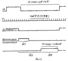
Функционирование узлов микроЭВМ, осуществляющих синхронизацию вертикальной развертки видеотерминала, описывается временной диаграммой, приведенной на фиг.4. Сигнал с выхода 48 вертикальной синхронизации контроллера ВТ передним фронтом переписывает информацию из регистра 12 в счетчик 13. Если в счетчике оказывается код, отличный от "0", на выходе элемента И 66 логического узла 14 устанавливается уровень лог."1", который пропускает через элемент И 67 сигналы, поступающие с выхода 47 горизонтальной синхронизации контроллера ВТ. Каждый из этих сигналов, воздействуя на счетный вход счетчика 13, уменьшает код, хранящийся в счетчике, на единицу. Таким образом, на выходе 57 логического узла 14 вырабатывается импульс положительной полярности длительностью, равной произведению периода горизонтальной синхронизации контроллера ВТ на величину, код которой хранится в регистре 12. Задний фронт импульса, выработанного логическим узлом 14 на выходе 57, запускает одновибраторы 15 и 17. Последний вырабатывает импульс вертикальной синхронизации видеотерминала необходимой для этого длительности. Задний фронт импульса, выработанного одновибратором 15, запускает одновибратор 16, сигнал с выхода которого блокирует пропускание видеосигнала через элемент ИЛИ 11 во время обратного хода луча по вертикали. The functioning of the nodes of the microcomputer, synchronizing the vertical scan of the video terminal, is described by the time diagram shown in figure 4. The signal from the VT
Описанный аппаратный механизм позволяет с помощью программы осуществлять плавное перемещение изображения на экране видеотерминала в вертикальном направлении. Пусть в исходном состоянии в регистре 12 записан код "1". Тогда положительная полка сигнала на выходе 57 логического узла будет иметь длительность один период частоты горизонтальной синхронизации. Следовательно, сигнал вертикальной синхронизации, поданный на видеотерминал, окажется смещенным относительно сигнала на одноименном выходе контроллера ВТ на один период горизонтальной синхронизации, а блокировка видеосигнала на элементе ИЛИ 11 окажется снятой при отображении первой строки растра первой символьной строки. Далее микропроцессор записывает в регистр 12 код "2". Теперь положительная полка сигнала на выходе 57 будет обладать длительностью в два периода частоты горизонтальной синхронизации, из-за чего соответствующим образом окажутся отодвинутыми сигналы вертикальной синхронизации и блокировки видеосигнала, вследствие чего отображение информации на экране начнется со второй строки растра первой символьной строки. Следует отметить, что поскольку интервал между импульсом вертикальной синхронизации, поступающим на видеотерминал, и снятием блокировки видеосигнала не изменяются, положение начала изображения на экране электронно-лучевой трубки не изменяется. Записывая в счетчик последовательно коды "3", "4",..."8", микропроцессор будет сдвигать изображение на 2, 3,...7 строк растра. После этого следует записать в регистр 12 код "1", сдвинув информацию в видеопамяти на одну строку символов вверх. The described hardware mechanism allows using the program to smoothly move the image on the screen of the video terminal in the vertical direction. Let in the initial state in the
Claims (1)
Priority Applications (1)
| Application Number | Priority Date | Filing Date | Title |
|---|---|---|---|
| SU4886577 RU2024928C1 (en) | 1990-11-26 | 1990-11-26 | Computer |
Applications Claiming Priority (1)
| Application Number | Priority Date | Filing Date | Title |
|---|---|---|---|
| SU4886577 RU2024928C1 (en) | 1990-11-26 | 1990-11-26 | Computer |
Publications (1)
| Publication Number | Publication Date |
|---|---|
| RU2024928C1 true RU2024928C1 (en) | 1994-12-15 |
Family
ID=21547562
Family Applications (1)
| Application Number | Title | Priority Date | Filing Date |
|---|---|---|---|
| SU4886577 RU2024928C1 (en) | 1990-11-26 | 1990-11-26 | Computer |
Country Status (1)
| Country | Link |
|---|---|
| RU (1) | RU2024928C1 (en) |
Cited By (1)
| Publication number | Priority date | Publication date | Assignee | Title |
|---|---|---|---|---|
| RU2209462C2 (en) * | 2000-06-08 | 2003-07-27 | Комарченко Петр Яковлевич | Microcomputer |
-
1990
- 1990-11-26 RU SU4886577 patent/RU2024928C1/en active
Non-Patent Citations (2)
| Title |
|---|
| Башков Е.А. Аппаратное и программное обеспечение зарубежных микро-ЭВМ, Киев, "Вища школа", 1990, с.206. * |
| Горшков Д. и др. Персональный радиолюбительский компьютер "Радио-86РК", Радио, N 4, 1986. * |
Cited By (1)
| Publication number | Priority date | Publication date | Assignee | Title |
|---|---|---|---|---|
| RU2209462C2 (en) * | 2000-06-08 | 2003-07-27 | Комарченко Петр Яковлевич | Microcomputer |
Similar Documents
| Publication | Publication Date | Title |
|---|---|---|
| US4200869A (en) | Data display control system with plural refresh memories | |
| US4399435A (en) | Memory control unit in a display apparatus having a buffer memory | |
| US4011556A (en) | Graphic display device | |
| EP0525986B1 (en) | Apparatus for fast copying between frame buffers in a double buffered output display system | |
| US3729730A (en) | Display system | |
| US4912771A (en) | Image memory apparatus | |
| RU2024928C1 (en) | Computer | |
| US4581611A (en) | Character display system | |
| JP3021810B2 (en) | Multi-port memory | |
| RU2023314C1 (en) | Device for representation of symbols on tv display screen | |
| SU1495780A1 (en) | Device for display of data on video monitor unit | |
| SU1437907A1 (en) | Device for displaying information on television indicator screen | |
| JPS5835592A (en) | display screen splitting device | |
| SU1536368A1 (en) | Information input device | |
| SU1453440A1 (en) | Device for displaying information on crt screen | |
| SU1674221A1 (en) | Data display unit | |
| SU1660021A1 (en) | DEVICE FOR TRANSFORMING IMAGES ¢ 7) | |
| JP2604153B2 (en) | Image Rewriting Method for Video Game Machine | |
| SU1566339A1 (en) | Device for presentation of graphic information | |
| SU1354183A1 (en) | Information displaying device | |
| RU1783509C (en) | Device for information input | |
| RU1772822C (en) | Device for displaying graphic data | |
| JPH0125981Y2 (en) | ||
| JPH087547B2 (en) | Display memory address device | |
| JPS6213690B2 (en) |