RU2018373C1 - Device for monitoring content of slime in magnetic suspension - Google Patents
Device for monitoring content of slime in magnetic suspension Download PDFInfo
- Publication number
- RU2018373C1 RU2018373C1 SU4857495A RU2018373C1 RU 2018373 C1 RU2018373 C1 RU 2018373C1 SU 4857495 A SU4857495 A SU 4857495A RU 2018373 C1 RU2018373 C1 RU 2018373C1
- Authority
- RU
- Russia
- Prior art keywords
- content
- signal
- magnetite
- suspension
- transducer
- Prior art date
Links
- 239000000725 suspension Substances 0.000 title claims abstract description 25
- 238000012544 monitoring process Methods 0.000 title description 2
- SZVJSHCCFOBDDC-UHFFFAOYSA-N iron(II,III) oxide Inorganic materials O=[Fe]O[Fe]O[Fe]=O SZVJSHCCFOBDDC-UHFFFAOYSA-N 0.000 claims abstract description 26
- 230000006698 induction Effects 0.000 claims abstract description 6
- 239000010802 sludge Substances 0.000 claims description 15
- 239000002002 slurry Substances 0.000 claims description 7
- 229910052500 inorganic mineral Inorganic materials 0.000 abstract description 2
- 239000011707 mineral Substances 0.000 abstract description 2
- 239000012530 fluid Substances 0.000 abstract 1
- 239000000126 substance Substances 0.000 abstract 1
- XLYOFNOQVPJJNP-UHFFFAOYSA-N water Substances O XLYOFNOQVPJJNP-UHFFFAOYSA-N 0.000 description 6
- 230000001939 inductive effect Effects 0.000 description 4
- 238000004364 calculation method Methods 0.000 description 2
- 230000007423 decrease Effects 0.000 description 2
- 230000005484 gravity Effects 0.000 description 2
- 239000007788 liquid Substances 0.000 description 2
- 239000003245 coal Substances 0.000 description 1
- 238000005516 engineering process Methods 0.000 description 1
- 238000005259 measurement Methods 0.000 description 1
- 238000012806 monitoring device Methods 0.000 description 1
- 238000005070 sampling Methods 0.000 description 1
- 238000000926 separation method Methods 0.000 description 1
- 230000006641 stabilisation Effects 0.000 description 1
- 238000011105 stabilization Methods 0.000 description 1
- 238000004804 winding Methods 0.000 description 1
Landscapes
- Investigating Or Analyzing Materials By The Use Of Magnetic Means (AREA)
Abstract
Description
Изобретение относится к устройствам для контроля содержания шлама в магнетитовой суспензии, в частности, при обогащении полезных ископаемых. The invention relates to devices for controlling the content of sludge in a magnetite suspension, in particular, in the enrichment of minerals.
Известно устройство для измерения содержания шлама в магнетитовой суспензии (авт. св. N 1194493, кл. В 03 В 13/00, 1984), содержащее два поплавковых жестко связанных датчика, измерительный прибор, датчик измерения содержания магнетита в суспензии, датчик измерения общей плотности суспензии, выполненные в виде индуктивных катушек, блок определения содержания шлама в суспензии, при этом индуктивная катушка содержания магнетита в суспензии размещена в первом поплавковом датчике, а индуктивная катушка общей плотности суспензии жестко соединена с вторым поплавковым датчиком, в ней помещен плунжер первого поплавкового датчика, а выходы индуктивных катушек общей плотности суспензии и содержания магнетита в суспензии электрически соединены через блок определения содержания шлама в суспензии с измерительным прибором. A device for measuring the content of sludge in a magnetite suspension (ed. St. N 1194493, class B 03 13/00, 1984), containing two float-tightly connected sensors, a measuring device, a sensor for measuring the content of magnetite in suspension, a sensor for measuring the total density suspensions made in the form of inductive coils, a block for determining the slurry content in the suspension, while the inductive coil of magnetite in the suspension is placed in the first float sensor, and the inductive coil of the total density of the suspension is rigidly connected to the second m float sensor, it is placed a plunger first float sensor, and the outputs of inductive coils overall density of the slurry and the content of magnetite in the slurry are electrically connected via the unit determining the content of the slurry in the slurry with the measuring instrument.
Недостатком данного устройства является низкая точность контроля содержания шлама в магнетитовой суспензии, обусловленная несовершенной конструкцией устройства, а также принципом определения содержания шлама в суспензии. The disadvantage of this device is the low accuracy of control of the content of sludge in a magnetite suspension, due to the imperfect design of the device, as well as the principle of determining the content of sludge in the suspension.
Целью изобретения является повышение точности контроля содержания шлама в магнетитовой суспензии. The aim of the invention is to improve the accuracy of control of the content of sludge in magnetite suspension.
Поставленная цель достигается тем, что устройство контроля содержания магнетита расположено в проточной камере устройства контроля плотности между отборниками давления на равном удалении от них, содержание шлама определяют из выражения
βш= 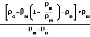
ρс - плотность суспензии;
ρм, ρб, ρш - соответственно плотность магнетита, воды, шлама.This goal is achieved by the fact that the device for controlling the content of magnetite is located in the flow chamber of the device for controlling the density between pressure taps at an equal distance from them, the slurry content is determined from the expression
β w =
ρ c is the density of the suspension;
ρ m , ρ b , ρ W - respectively, the density of magnetite, water, sludge.
На чертеже изображено предлагаемое устройство. The drawing shows the proposed device.
В проточной камере 1 устройства контроля плотности с разнесенными по высоте Н отборниками давления 2 расположена индукционная катушка 3 (устройство контроля содержания магнетита). Отборники давления соединены посредством импульсных трубок 4 с первичным преобразователем 6 сигнала содержания магнетита, выход которого соединен с первым входом блока 7 масштабирования сигнала содержания магнетита. Второй вход блока 7 соединен с выходом задатчика 8 масштабного коэффициента, а выход - с вторым входом блока 9 суммирования, первый вход которого соединен с первичным преобразователем 5 сигнала плотности, третий вход - с задатчиком 10 сигнала удельного веса воды, а выход - с блоком 12 умножения, другой вход которого соединен с задатчиком 11 коэффициента весомости, а выход - с вторичным прибором 13. Блоки 7-12 представляют собой блок 14 определения содержания шлама. An induction coil 3 (a magnetite content monitoring device) is located in the flow chamber 1 of the density control device with pressure pickups 2 spaced apart in height H. The pressure samplers are connected by means of impulse tubes 4 to the primary transducer 6 of the magnetite content signal, the output of which is connected to the first input of the magnetite content signal scaling unit 7. The second input of block 7 is connected to the output of the scale factor adjuster 8, and the output is connected to the second input of the summation block 9, the first input of which is connected to the primary transducer 5 of the density signal, the third input is connected to the adjuster 10 of the specific gravity water signal, and the output is connected to block 12 multiplication, the other input of which is connected to the setpoint generator 11 of the weight coefficient, and the output to the secondary device 13. Blocks 7-12 are a block 14 for determining the content of sludge.
Устройство работает следующим образом. The device operates as follows.
При прохождении жидкости по вертикальному участку проточной камеры 1 устройства возникает перепад давлений по высоте Н базы измерения, контролируемый отборниками давления 2. Разностное давление, пропорциональное плотности жидкости, воспринимается первичным преобразователем 5 сигнала плотности, унифицированный выходной сигнал которого поступает на вход блока 9 суммирования. Одновременно производится контроль содержания магнетита в суспензии с помощью индукционной катушки 3, размещенной в устройстве контроля плотности между отборниками давления 2. When the liquid passes through the vertical section of the flow chamber 1 of the device, a pressure differential occurs along the height H of the measurement base, controlled by pressure sampling devices 2. A differential pressure proportional to the density of the liquid is perceived by the density signal primary transducer 5, the unified output signal of which is input to the summing unit 9. At the same time, the magnetite content in the suspension is monitored using an induction coil 3 located in the density control device between the pressure pickups 2.
При прохождении магнетитовой суспензии через полость катушки во вторичной обмотке наводится ЭДС, пропорциональная содержанию магнетита в суспензии. Сигнал поступает на вход первичного преобразователя 6 сигнала содержания магнетита, унифицированный выходной сигнал которого проходит через блок 7 масштабирования сигнала содержания магнетита, масштабные коэффициенты которого задаются задатчиком 8, и поступает на второй вход блока 9 суммирования. На третий вход поступает сигнал от задатчика 10 сигнала удельного веса воды. Блок суммирования реализует алгоритм
![]()
![]()
![]()
βм - содержание магнетита в суспензии;
K1=![]()
![]()
К2 = ρв = соnst - плотность воды;
ρм - плотность магнетита.When the magnetite suspension passes through the cavity of the coil in the secondary winding, an EMF is proportional to the magnetite content in the suspension. The signal is fed to the input of the primary converter 6 of the magnetite content signal, the unified output signal of which passes through the scaling unit 7 of the magnetite content signal, the scale factors of which are set by the adjuster 8, and is fed to the second input of the summing unit 9. The third input receives a signal from the setter 10 of the signal specific gravity of water. The summing unit implements the algorithm
![]()
![]()
![]()
β m - the content of magnetite in suspension;
K 1 = ![]()
![]()
To 2 = ρ in = const - the density of water;
ρ m is the density of magnetite.
Выходной сигнал блока суммирования поступает на вход блока 12 умножения, на другой вход которого поступает сигнал от задатчика 11 коэффициента весомости. На выходе блока 14 определения содержания шлама формируется сигнал, вычисление которого описывается следующим алгоритмом
βш= ![]()
![]()
![]()
ρш - плотность шлама;
βш - содержание шлама;
βм - содержание магнетита.The output signal of the summing unit is fed to the input of the multiplication unit 12, the other input of which receives a signal from the weighting unit 11. At the output of block 14 for determining the content of sludge, a signal is generated, the calculation of which is described by the following algorithm
β w = ![]()
![]()
![]()
ρ W - the density of the sludge;
β W - sludge content;
β m - the content of magnetite.
Данный алгоритм был получен в результате решения системы двух уравнений
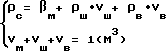
![]()
![]()
Из уравнения (4) определяется объем воды и полученное выражение подставляется в уравнение (3). The volume of water is determined from equation (4) and the resulting expression is substituted into equation (3).
Реализация алгоритма (2) с применением микропроцессорной техники, а также использование первичных преобразователей, погрешность контроля которых не превышает 0,5% (например, "САПФИР"-22ДД), позволяют осуществлять контроль содержания шлама с погрешностью, не превышающей 20%, при плотности суспензии до 1800 кг/м3. Следует отметить, что эта погрешность уменьшается с понижением плотности суспензии. Расчет максимальной погрешности производится путем подстановки предельных отклонений контролируемых параметров в формулу (2). Контроль содержания шлама в суспензии с последующей стабилизацией его на заданном уровне оказывает влияние на устойчивость суспензии в обогатительном аппарате, а следовательно, приводит к улучшению качества разделений исходного угля.The implementation of algorithm (2) using microprocessor technology, as well as the use of primary converters, the control error of which does not exceed 0.5% (for example, SAPFIR-22DD), allows controlling the content of sludge with an error not exceeding 20% at a density suspensions up to 1800 kg / m 3 . It should be noted that this error decreases with a decrease in the density of the suspension. The calculation of the maximum error is made by substituting the maximum deviations of the controlled parameters in the formula (2). Monitoring the content of sludge in the suspension with its subsequent stabilization at a given level affects the stability of the suspension in the beneficiation apparatus, and therefore leads to an improvement in the quality of the separation of the initial coal.
Claims (1)
Priority Applications (1)
| Application Number | Priority Date | Filing Date | Title |
|---|---|---|---|
| SU4857495 RU2018373C1 (en) | 1990-08-06 | 1990-08-06 | Device for monitoring content of slime in magnetic suspension |
Applications Claiming Priority (1)
| Application Number | Priority Date | Filing Date | Title |
|---|---|---|---|
| SU4857495 RU2018373C1 (en) | 1990-08-06 | 1990-08-06 | Device for monitoring content of slime in magnetic suspension |
Publications (1)
| Publication Number | Publication Date |
|---|---|
| RU2018373C1 true RU2018373C1 (en) | 1994-08-30 |
Family
ID=21531164
Family Applications (1)
| Application Number | Title | Priority Date | Filing Date |
|---|---|---|---|
| SU4857495 RU2018373C1 (en) | 1990-08-06 | 1990-08-06 | Device for monitoring content of slime in magnetic suspension |
Country Status (1)
| Country | Link |
|---|---|
| RU (1) | RU2018373C1 (en) |
Cited By (1)
| Publication number | Priority date | Publication date | Assignee | Title |
|---|---|---|---|---|
| RU2142851C1 (en) * | 1998-05-13 | 1999-12-20 | Батуев Александр Аркадьевич | Crushing-screening unit |
-
1990
- 1990-08-06 RU SU4857495 patent/RU2018373C1/en active
Non-Patent Citations (1)
| Title |
|---|
| Авторское свидетельство СССР N 1194493, кл. B 03B 13/00, 1984. * |
Cited By (1)
| Publication number | Priority date | Publication date | Assignee | Title |
|---|---|---|---|---|
| RU2142851C1 (en) * | 1998-05-13 | 1999-12-20 | Батуев Александр Аркадьевич | Crushing-screening unit |
Similar Documents
| Publication | Publication Date | Title |
|---|---|---|
| EP0416866B1 (en) | Electromagnetic flowmeter utilizing magnetic fields of a plurality of frequencies | |
| RU96107107A (en) | ELECTROMAGNETIC FLOW METER WITH EMPTY DETECTOR | |
| CA2039977A1 (en) | Flow measuring apparatus | |
| RU2018373C1 (en) | Device for monitoring content of slime in magnetic suspension | |
| RU2030713C1 (en) | Electromagnetic flow meter | |
| RU12240U1 (en) | ELECTROMAGNETIC FLOW METER SIGNAL CIRCUIT | |
| CN101843993A (en) | On-line weighing and sensing method for regulating and controlling bottom flow of solid-liquid separation box hopper device | |
| RU2156962C2 (en) | Technique of ultrasonic measurement of level of liquid | |
| JPS5654314A (en) | Flow-rate measuring method by electromagnetic flow meter | |
| SU921627A1 (en) | Apparatus for determining content of magnetic fraction in iron ore pulp solid phase | |
| CN2276151Y (en) | Liquid level sensor device | |
| SU1169751A1 (en) | Defice for monitoring foam layer thickness and flotation pulp level | |
| SU367365A1 (en) | METHOD OF MEASURING THE DENSITY OF IRON ORE PULP | |
| SU1067360A1 (en) | Method of measuring liquid flow speed | |
| SU932252A1 (en) | Level indicator | |
| SU1056113A1 (en) | Geoelectric prospecting method | |
| SU665248A1 (en) | Liquid density meter | |
| SU429318A1 (en) | METHOD FOR DETERMINING A PARTICULAR WEIGHT OF A SOLID IN A TWO-PHASE FLOW WITH FERROMAGNETIC INCLUSIONS | |
| SU1394042A1 (en) | Device for measuring consumption of solid phase in mixture | |
| SU924516A1 (en) | Float-type level indicator | |
| RU96111810A (en) | METHOD FOR GRADING AND VERIFICATION OF GAS FLOW METER AND DEVICE FOR ITS IMPLEMENTATION | |
| SU864943A1 (en) | Fluid-tightness testing apparatus | |
| SU1038912A1 (en) | Probe for measuring magnetic susceptibility | |
| SU894546A1 (en) | Device for checking hardness | |
| RU2104496C1 (en) | Flowmeter |