RU2018103C1 - Device for measuring kinematic characteristics of track-laying vehicle - Google Patents
Device for measuring kinematic characteristics of track-laying vehicle Download PDFInfo
- Publication number
- RU2018103C1 RU2018103C1 SU4920647A RU2018103C1 RU 2018103 C1 RU2018103 C1 RU 2018103C1 SU 4920647 A SU4920647 A SU 4920647A RU 2018103 C1 RU2018103 C1 RU 2018103C1
- Authority
- RU
- Russia
- Prior art keywords
- rotation
- horizontal
- rod
- fixed
- sensor
- Prior art date
Links
- 238000005259 measurement Methods 0.000 abstract description 5
- 238000004642 transportation engineering Methods 0.000 abstract description 2
- 239000000126 substance Substances 0.000 abstract 1
- 238000010586 diagram Methods 0.000 description 1
- 238000005096 rolling process Methods 0.000 description 1
Images
Landscapes
- Vehicle Body Suspensions (AREA)
Abstract
Description
Изобретение относится к транспортному машиностроению и может быть использовано при исследовании движения гусеничных машин. The invention relates to transport engineering and can be used in the study of the movement of tracked vehicles.
Известно устройство для измерения кинематических характеристик гусеничной машины, содержащее тягу, соединенную одним концом со скрепленным с корпусом гусеничной машины кронштейном посредством двухстепенного шарнира с горизонтальной и вертикальной осями вращения, измерительное колесо для взаимодействия с опорной поверхностью с горизонтальной осью вращения, закрепленное на другом конце тяги, пружину, закрепленную одним концом на тяге, установленный на измерительном колесе импульсный датчик частоты вращения измерительного колеса, датчики углов поворота тяги в горизонтальной и вертикальной плоскостях, имеющие неподвижные исполнительные элементы и подвижные чувствительные элементы, последние из которых соединены соответственно с вертикальной и горизонтальной осями двухстепенного шарнира, и блок регистрации, к входам которого подключены упомянутые датчики [1]. A device is known for measuring the kinematic characteristics of a tracked vehicle, comprising a rod connected at one end to a bracket fastened to the casing of the tracked vehicle using a two-stage hinge with horizontal and vertical axes of rotation, a measuring wheel for interacting with a supporting surface with a horizontal axis of rotation, mounted on the other end of the rod, a spring fixed at one end to the rod mounted on the measuring wheel pulse sensor speed of the measuring wheel, d tchiki rotation angles thrust in the horizontal and vertical planes, having fixed and movable actuators sensing elements, the latter of which are connected respectively with the vertical and horizontal axes of the two-stage hinge, and the recording unit, which are connected to inputs of said sensor [1].
Это устройство позволяет измерить ряд кинематических характеристик гусеничной машины, но имеет следующие недостатки: низкую достоверность из-за деформации пружины при вертикальном перемещении колеса. Так как один конец пружины закреплен к тяге, а другой - к кронштейну, скрепленному с корпусом гусеничной машины, то при повороте последней появляется составляющая усилия пружины, которая стремится сместить тягу с колесом в боковом направлении. Такое смещение приводит к боковому уводу колеса и, следовательно, снижению точности измерений. Устройство обладает малыми функциональными возможностями, не позволяет определить основные характеристики поворота гусеничной машины - угловую скорость поворота, скорости буксования гусениц, радиус поворота и смещение полюса поворота, так как для определения последних необходимо измерить скорости и выявить траектории движения обоих (забегающего и отстающего) бортов гусеничной машины. This device allows you to measure a number of kinematic characteristics of the tracked vehicle, but has the following disadvantages: low reliability due to deformation of the spring during vertical movement of the wheel. Since one end of the spring is fixed to the rod, and the other to the bracket fastened to the caterpillar body, when the latter is turned, a component of the spring force appears, which tends to shift the rod and wheel in the lateral direction. Such an offset leads to lateral abduction of the wheel and, consequently, to a decrease in measurement accuracy. The device has low functional capabilities, it does not allow to determine the basic characteristics of the rotation of the tracked vehicle - the angular speed of rotation, the speed of slipping of the tracks, the turning radius and the offset of the pole of rotation, since to determine the latter it is necessary to measure the speeds and identify the trajectories of both (running and lagging) tracked sides cars.
Цель изобретения - повышение точности измерений и расширение функциональных возможностей. The purpose of the invention is improving the accuracy of measurements and expanding functionality.
Достигается это тем, что в устройстве для измерения кинематических характеристик машины, содержащем тягу, соединенную одним концом со скрепленным с корпусом гусеничной машины кронштейном посредством двухстепенного шарнира с горизонтальной и вертикальной осями вращения, измерительное колесо для взаимодействия с опорной поверхностью с горизонтальной осью вращения, закрепленное на другом конце тяги, пружину, закрепленную одним концом на тяге, установленный на измерительном колесе импульсный датчик частоты вращения измерительного колеса, датчики углов поворота тяги в горизонтальной и вертикальной плоскостях, имеющие неподвижные исполнительные элементы и подвижные чувствительные элементы, последние из которых соединены соответственно с вертикальной и горизонтальной осями двухстепенного шарнира, и блок регистрации, к входам которого подключены упомянутые датчики, согласно изобретению другим концом пружина закреплена на вертикальной оси шарнира, причем неподвижный исполнительный элемент датчика угла поворота тяги в горизонтальной плоскости закреплен на кронштейне, а неподвижный исполнительный элемент датчика угла поворота тяги в вертикальной плоскости закреплен на тяге, при этом на горизонтальной оси измерительного колеса установлены тензодатчики, через усилитель подключенные к блоку регистрации. This is achieved by the fact that in the device for measuring the kinematic characteristics of the machine, comprising a rod connected at one end to a bracket fastened to the caterpillar vehicle body by means of a two-stage hinge with horizontal and vertical axes of rotation, a measuring wheel for interacting with a supporting surface with a horizontal axis of rotation, mounted on the other end of the rod, a spring fixed at one end to the rod, an impulse speed sensor mounted on the measuring wheel ca, thrust angle sensors in the horizontal and vertical planes having fixed actuators and movable sensing elements, the latter of which are connected respectively to the vertical and horizontal axes of the two-stage hinge, and a registration unit, to the inputs of which the sensors are connected, according to the invention, the other end is a spring fixed on the vertical axis of the hinge, and the fixed actuator element of the sensor for the angle of rotation of the thrust in the horizontal plane is fixed to the bracket not, but the fixed actuating element of the rod angle sensor in the vertical plane is mounted on the rod, while strain gauges are installed on the horizontal axis of the measuring wheel through an amplifier connected to the registration unit.
Кроме того, устройство снабжено установленным на вертикальной оси шарнира и подключенным к блоку регистрации гироскопическим датчиком угловой скорости, дополнительным кронштейном, двухстепенным шарниром, тягой, измерительным колесом, датчиками углов поворота тяги в горизонтальной и вертикальной плоскостях, импульсным датчиком частоты вращения, выполненными, установленными и связанными между собой аналогично первым, причем оба кронштейна закреплены симметрично друг другу по обе стороны от продольной оси машины, а вертикальные оси двухстепенных шарниров расположены на одной прямой, перпендикулярной продольной оси машины. In addition, the device is equipped with a gyroscopic angular velocity sensor mounted on the vertical axis of the hinge and connected to the recording unit, an additional bracket, a two-stage hinge, a thrust, a measuring wheel, thrust angle sensors in horizontal and vertical planes, a pulse speed sensor, made, installed and interconnected similarly to the first, with both brackets mounted symmetrically to each other on both sides of the longitudinal axis of the machine, and the vertical axis the hinged joints are located on one straight line perpendicular to the longitudinal axis of the machine.
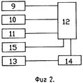
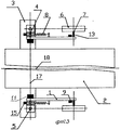
На фиг.1 изображено устройство, вид сбоку; на фиг.2 - структурная схема измерительного комплекса; на фиг.3 - то же, вид сверху. Figure 1 shows the device, side view; figure 2 is a structural diagram of a measuring complex; figure 3 is the same, top view.
Устройство содержит тягу 1, соединенную одним концом со скрепленным с корпусом 2 гусеничной машины кронштейном 3 посредством двухстепенного шарнира с горизонтальной 4 и вертикальной 5 осями вращения; колесо 6, шарнирно установленное на дополнительной горизонтальной оси 7, смонтированной на другом конце тяги 1, пружину 8, закрепленную одним концом к тяге 1, импульсный датчик 9 частоты вращения колеса 6, первый датчик 10 угла поворота, подвижная часть которого соединена с вертикальной осью 5 вращения, второй датчик 11 угла поворота, подвижная часть которого соединена с горизонтальной осью 4 вращения , блок регистрации 12, к входам которого подключены упомянутые датчики 9, 10, 11. Свободный конец пружины 8 прикреплен к вертикальной оси 5 вращения, корпус первого датчика 10 угла поворота закреплен на кронштейне 3, корпус второго датчика 11 угла поворота закреплен на тяге 1, дополнительная горизонтальная ось 7 выполнена тензометрической, а соответствующие тензодатчики 13 подключены к усилителю 14, выход которого подключен к входу блока регистрации 12. Устройство снабжено гироскопическим датчиком 15 угловой скорости, скрепленным с вертикальной осью 5 вращения, выход которого подключен к входу блока регистрации 12 и установлено по обоим бортам гусеничной машины так, что точки пересечения вертикальных осей 5 вращения с опорной поверхностью 16 располагаются на одной линии 17, перпендикулярной продольной оси 18 гусеничной машины. The device comprises a rod 1, connected at one end to a
Работает устройство следующим образом. При движении гусеничной машины импульсный датчик 9 вырабатывает последовательность импульсов, частота следования которых пропорциональна скорости движения соответствующего борта гусеничной машины, первый датчик 10 угла поворота вырабатывает сигнал, пропорциональный углу поворота, и характеризует траекторию движения соответствующего борта, второй датчик 11 - сигнал, определяющий профиль опорной поверхности 16, тензодатчики 13, расположенные на дополнительной горизонтальной оси 7, сигнал, пропорциональный усилию прижатия колеса 6 к опорной поверхности 16, датчик 15 угловой скорости - сигнал, пропорциональный угловой скорости поворота. Сигналы с датчиков 9, 10, 11 и 15 непосредственно поступают на входы блока регистрации 12. Сигнал с тензодатчиков 13 вначале усиливается с помощью усилителя 14, а затем также поступают на вход блока регистрации 12. Датчики 9, 10, 11 и 15, усилитель 14 и блок-регистрации 12 запитываются от источников стабилизированного напряжения (условно не показаны). The device operates as follows. When the tracked vehicle is moving, the
Измерение усилия прижатия колеса 6 к опорной поверхности 16 позволяет учесть изменение радиуса качения колеса 6 и повысить точность определения скорости движения. Так как один конец пружины закреплен к тяге 1, а другой - к вертикальной оси 5 вращения, то исключается боковой увод колеса 6 при поворота гусеничной машины и повышается точность измерения траектории движения. Введение датчика 15 угловой скорости позволяет определить угловую скорость поворота. Установка устройства на левом и правом бортах позволяет измерить скорости и выявить траектории движения обоих (забегающего и отстающего) бортов, что позволяет после обработки результатов измерения определить ряд основных кинематических характеристик криволинейного движения (поворота) гусеничной машины - радиус поворота, смещение полюса поворота и скорости буксования гусениц. The measurement of the pressure of the
Claims (2)
Priority Applications (1)
| Application Number | Priority Date | Filing Date | Title |
|---|---|---|---|
| SU4920647 RU2018103C1 (en) | 1991-03-19 | 1991-03-19 | Device for measuring kinematic characteristics of track-laying vehicle |
Applications Claiming Priority (1)
| Application Number | Priority Date | Filing Date | Title |
|---|---|---|---|
| SU4920647 RU2018103C1 (en) | 1991-03-19 | 1991-03-19 | Device for measuring kinematic characteristics of track-laying vehicle |
Publications (1)
| Publication Number | Publication Date |
|---|---|
| RU2018103C1 true RU2018103C1 (en) | 1994-08-15 |
Family
ID=21565876
Family Applications (1)
| Application Number | Title | Priority Date | Filing Date |
|---|---|---|---|
| SU4920647 RU2018103C1 (en) | 1991-03-19 | 1991-03-19 | Device for measuring kinematic characteristics of track-laying vehicle |
Country Status (1)
| Country | Link |
|---|---|
| RU (1) | RU2018103C1 (en) |
Cited By (1)
| Publication number | Priority date | Publication date | Assignee | Title |
|---|---|---|---|---|
| RU2171461C1 (en) * | 1999-12-15 | 2001-07-27 | ФПГ "Сибагромаш" | Method and apparatus for determining coordinates of tractor-mounted unit in the field |
-
1991
- 1991-03-19 RU SU4920647 patent/RU2018103C1/en active
Non-Patent Citations (1)
| Title |
|---|
| Авторское свидетельство СССР N 1323898, кл. G 01M 17/00, 1987. * |
Cited By (1)
| Publication number | Priority date | Publication date | Assignee | Title |
|---|---|---|---|---|
| RU2171461C1 (en) * | 1999-12-15 | 2001-07-27 | ФПГ "Сибагромаш" | Method and apparatus for determining coordinates of tractor-mounted unit in the field |
Similar Documents
| Publication | Publication Date | Title |
|---|---|---|
| US6419240B1 (en) | Vehicle roll control | |
| US6588769B2 (en) | Vehicle roll control | |
| US4951198A (en) | Friction detecting device for vehicles | |
| JPH0249136A (en) | Apparatus for measuring effect of transverse window on vehicle, especially automobile or the like | |
| JP3285257B2 (en) | How to detect reverse travel of a car | |
| KR920002019B1 (en) | System for determining the movement of a track vehicle | |
| WO2005023614A3 (en) | Stability control apparatus and load mesuring instrument for wheel supporting rolling bearing unit | |
| EP1031814A4 (en) | ANGLE SPEED SENSOR | |
| JPH09152389A (en) | Shock absorber damping force measuring device | |
| RU2018103C1 (en) | Device for measuring kinematic characteristics of track-laying vehicle | |
| JPH01267462A (en) | Apparatus for measuring slip angle of vehicle | |
| US5801507A (en) | Acceleration sensor | |
| JP2689357B2 (en) | Relative direction detection method | |
| JP3219204B2 (en) | Road surface unevenness measurement vehicle | |
| GB2448820A (en) | Dynamic percent grade measurement device | |
| JPS63145118A (en) | Torsional quantity detector for stabilizer | |
| JPH0536219B2 (en) | ||
| JPS6112010U (en) | Vehicle track and road surface inspection device | |
| JP3244619B2 (en) | Moving object state determination device | |
| SU1014783A1 (en) | Apparatus for determining spatial displacement of rail vehicle body | |
| CN212267421U (en) | A vehicle rollover prevention device | |
| JPH06344942A (en) | Wheel alignment measuring method and device | |
| KR200164499Y1 (en) | Robot for measuring outlook | |
| SU1717994A1 (en) | Dynamometric device for testing transport vehicle | |
| KR0184748B1 (en) | How to measure the slip angle of a tire wheel |