RU2017103C1 - Device for measuring inertial characteristics of articles - Google Patents
Device for measuring inertial characteristics of articles Download PDFInfo
- Publication number
- RU2017103C1 RU2017103C1 SU4883317A RU2017103C1 RU 2017103 C1 RU2017103 C1 RU 2017103C1 SU 4883317 A SU4883317 A SU 4883317A RU 2017103 C1 RU2017103 C1 RU 2017103C1
- Authority
- RU
- Russia
- Prior art keywords
- product
- axis
- faceplate
- platform
- mass
- Prior art date
Links
- 230000000694 effects Effects 0.000 abstract description 2
- 238000011089 mechanical engineering Methods 0.000 abstract description 2
- 239000000126 substance Substances 0.000 abstract 1
- 230000010355 oscillation Effects 0.000 description 16
- 238000005259 measurement Methods 0.000 description 6
- 238000000034 method Methods 0.000 description 3
- 101100234408 Danio rerio kif7 gene Proteins 0.000 description 2
- 101100221620 Drosophila melanogaster cos gene Proteins 0.000 description 2
- 101100398237 Xenopus tropicalis kif11 gene Proteins 0.000 description 2
- 230000003534 oscillatory effect Effects 0.000 description 2
- 238000004364 calculation method Methods 0.000 description 1
- 230000000052 comparative effect Effects 0.000 description 1
- 230000014509 gene expression Effects 0.000 description 1
- 238000005461 lubrication Methods 0.000 description 1
- 230000008092 positive effect Effects 0.000 description 1
- 230000003068 static effect Effects 0.000 description 1
Images
Landscapes
- Vibration Prevention Devices (AREA)
Abstract
Description
Изобретение относится к машиностроению и может быть использовано для определения инерционных характеристик изделий. The invention relates to mechanical engineering and can be used to determine the inertial characteristics of products.
Наиболее близким по технической сущности к изобретению является устройство, содержащее установленный на основании корпус, размещенную в нем колебательную систему, выполненную в виде платформы, связанной торсионом с корпусом, планшайбу для закрепления изделия и узел поворота планшайбы относительно оси, параллельной оси платформы. С помощью этого устройства можно определить массу, две координаты центра масс и момент инерции относительности, проходящей через центр масс изделия. The closest in technical essence to the invention is a device containing a housing mounted on the base, an oscillating system placed therein, made in the form of a platform connected by a torsion to the housing, a faceplate for securing the product, and a node for turning the faceplate relative to an axis parallel to the axis of the platform. Using this device, you can determine the mass, two coordinates of the center of mass and the moment of inertia of relativity passing through the center of mass of the product.
Недостатком устройств является сравнительная ограниченность технологических возможностей, так как с его помощью невозможно определить третью координату центра масс и центральный эллипсоид инерции изделия. The disadvantage of the device is the comparative limited technological capabilities, since it is impossible to determine the third coordinate of the center of mass and the central inertia ellipsoid of the product with its help.
Цель изобретения - расширение эксплуатационных возможностей устройства для определения инерционных характеристик изделия. The purpose of the invention is the expansion of the operational capabilities of the device for determining the inertial characteristics of the product.
Поставленная цель достигается тем, что устройство для определения инерционных характеристик изделия, содержащее установленный на основании корпус, размещенную в нем колебательную систему, выполненную в виде платформы, связанной торсионом с корпусом, планшайбу для закрепления изделия и узел поворота планшайбы относительно вертикальной оси, параллельной оси платформы. Новым является то, что устройство снабжено дополнительным узлом поворота планшайбы относительно наклонной оси, расположенным между платформой и основным узлом поворота планшайбы, а сама планшайба выполнена поворотной относительно оси, совпадающей с осью платформы. This goal is achieved by the fact that the device for determining the inertial characteristics of the product, comprising a housing mounted on the base, an oscillating system placed in it, made in the form of a platform connected by a torsion bar with the housing, a faceplate for securing the product and a node for turning the faceplate relative to a vertical axis parallel to the axis of the platform . What is new is that the device is equipped with an additional node for turning the faceplate relative to the inclined axis located between the platform and the main node for turning the faceplate, and the faceplate itself is made rotatable with respect to the axis coinciding with the axis of the platform.
Предложенная совокупность признаков обеспечивает возможность дополнительно определять третью координату центра масс изделия и центральный эллипсоид инерции, что создает положительный эффект. The proposed set of features provides the ability to additionally determine the third coordinate of the center of mass of the product and the central ellipsoid of inertia, which creates a positive effect.
Проведенный поиск по патентной и научно-технической литературе не выявил технических решений с аналогичной совокупностью отличительных признаков. The search in the patent and scientific and technical literature did not reveal technical solutions with a similar set of distinctive features.
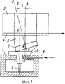
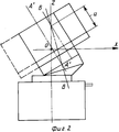
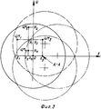
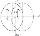
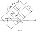
На фиг. 1 изображено предлагаемое устройство; на фиг. 2 - то же, после поворота планшайбы на 180о с помощью дополнительного узла поворота; на фиг. 3 и 4 - положения проекций центра масс на горизонтальную плоскость при различных углах поворота планшайбы с помощью основного и дополнительного узлов поворота; на фиг. 5 - фронтальные проекции центра масс при наклонном положении изделия.In FIG. 1 shows the proposed device; in FIG. 2 - the same after turning the chuck 180 by means of an additional pivot assembly; in FIG. 3 and 4 - the position of the projections of the center of mass on the horizontal plane at various angles of rotation of the faceplate using the primary and secondary rotation nodes; in FIG. 5 - frontal projections of the center of mass with an inclined position of the product.
Устройство содержит установленный на основание корпус 1, размещенную в нем колебательную систему, выполненную в виде платформы 2, связанной торсионом 3 с корпусом 1, поворотную относительно оси планшайбу 4 для закрепления изделия 5, узел поворота 6 планшайбы 4 относительно вертикальной оси А-А, параллельной оси О платформы 2, и дополнительный узел поворота 7 планшайбы 4 относительно наклонной оси Б-Б, размещенный между платформой 2 и основным узлом поворота 6. The device comprises a
Устройство для определения инерционных характеристик изделия работает следующим образом. A device for determining the inertial characteristics of the product operates as follows.
По трубопроводу 8 в зазор между корпусом 1 и платформой 2 подается сжатый воздух, обеспечивающий газовую смазку с малым коэффициентом трения между корпусом 1 и платформой 2. На планшайбе 4 крепится изделие 5 (фиг. 1). Платформу 2 принудительно закручивают на угол 1-5оотносительно оси OZ и отпускают. Платформа 2 вместе с изделием 5 начинает совершать свободные колебания. Измеряют период колебаний Т1-. Затем с помощью основного узла поворота 6 поворачивают планшайбу 4 с изделием 5 на 90о вокруг оси А-А по ходу часовой стрелки. Таким образом изделие, изменяя положение относительно оси колебаний, не меняет пространственной угловой ориентации, т.е. перемещается поступательно относительно оси колебаний. В этом положении измеряют период колебаний Т2. Затем измеряют период колебаний Т3, после дальнейшего поворота планшайбы 4 с помощью основного узла поворота 6 еще на 90о и разворота изделия в обратную сторону на 90о и после этого измеряют период колебаний Т4 после дальнейших аналогичных поворотов планшайбы 4 и изделия 5.
На фиг. 3 схематически показаны проекции центра масс изделия (ЦМ) и контуры сечения изделия (круг) в четырех описанных положениях изделия. In FIG. 3 schematically shows the projection of the center of mass of the product (CM) and the contours of the section of the product (circle) in the four described positions of the product.
После описанных операций с помощью дополнительного узла поворота 7 изделие приводят в наклонное положение (фиг. 2) и измеряют период колебаний Т5. Затем производят поворот планшайбы 4 с изделием на 180о с помощью основного узла поворота 6 и разворачивают изделие на планшайбе 4 на 180о вокруг своей оси. При этом изделие займет положение, показанное на фиг. 2 пунктиром. Производят в этом положении измерение периода колебаний Т6.After the described operations using an
На фиг. 3 схематически показаны проекции центра масс изделия и контура центрального сечения изделия в двух последних наклонных положениях изделия. In FIG. 3 schematically shows the projection of the center of mass of the product and the contour of the central section of the product in the last two inclined positions of the product.
После этого производят еще три измерения периодов колебаний Т7, Т8и Т9 после разворота изделия на планшайбе 4 вокруг собственной оси на углы, соответственно, 45, 45 и 180о. Последние три угла могут быть произвольными, но с учетом минимума погрешностей при вычислениях указанные углы оптимальны (в этом можно убедиться с помощью известных методов статического моделирования процесса определения инерционных характеристик с помощью описываемого алгоритма на ЭВМ). Из тех же соображений угол наклона оси Б-Б должен быть равен 22,5о, хотя он тоже может быть равен производным в интервале 0-45о. Выбор угла α на практике может ограничиваться габаритами и жесткостью конструкции изделия.After that, three more measurements of the oscillation periods T 7 , T 8 and T 9 are made after the product is turned on the
Применяя известные зависимости между моментом инерции унифилярного маятника, которым является предлагаемое устройство, и периодом его колебаний (Гернет М. М. и Ратобыльский В.Ф. Определение моментов инерции. М.: Машиностроение, 1969, с. 69), и введя обозначение K = ![]()
Ii=kTi 2 , где i - номер измерения периода колебаний,
Ii - соответствующий момент инерции колебательной системы, относительно оси OZ.Applying the known dependencies between the moment of inertia of the unifilar pendulum, which is the proposed device, and the period of its oscillations (Gernet M.M. and Ratobylsky V.F. = ![]()
I i = kT i 2 , where i is the measurement number of the period of oscillation,
I i - the corresponding moment of inertia of the oscillatory system relative to the axis OZ.
При первых четырех измерениях изделие не изменяет своей угловой пространственной ориентации относительно оси колебаний, поэтому можно записать
I01 + I1 + m (x1 2 + y1 2) = kT1 2,
I02 + I1 + m (x2 2 + y2 2) = kT2 2,
I03 + I1 + m (x3 2 + y3 2) = kT3 2,
I04 + I1 + m (x4 2 + y4 2) = kT4 2, I01 - момент инерции колебательной системы без изделия при соответствующем измерении периода колебаний;
I1 - момент инерции изделия относительно оси, проходящей через центр масс изделия и параллельной оси колебаний;
m - масса изделия;
xi и yi - координаты центра масс изделия;
(xi 2 + yi 2) - квадрат расстояния между центральной осью и осью колебаний.In the first four measurements, the product does not change its angular spatial orientation relative to the axis of oscillation, therefore, we can write
I 01 + I 1 + m (x 1 2 + y 1 2 ) = kT 1 2 ,
I 02 + I 1 + m (x 2 2 + y 2 2 ) = kT 2 2 ,
I 03 + I 1 + m (x 3 2 + y 3 2 ) = kT 3 2 ,
I 04 + I 1 + m (x 4 2 + y 4 2 ) = kT 4 2 , I 01 - moment of inertia of the oscillatory system without the product with the corresponding measurement of the period of oscillations;
I 1 - the moment of inertia of the product relative to the axis passing through the center of mass of the product and parallel to the axis of oscillation;
m is the mass of the product;
x i and y i are the coordinates of the center of mass of the product;
(x i 2 + y i 2 ) is the square of the distance between the central axis and the axis of oscillation.
Учитывая геометрические соотношения (фиг. 3) между координатами центра масс изделия при различных положениях изделия:
x2 = x1 + l,
y2 = y1 + l,
x3 = x1 + 2l,
y3 = y1,
x4 = x1 + l,
y4 = y1 - l, из системы четырех уравнений найдем:
Xl=X4= ![]()
Yl=Y1= ![]()
m = ![]()
При пятом и шестом измерениях изделие также не изменяет своей угловой пространственной ориентации относительно оси колебаний. Запишем аналогично:
I05 + I2 + m (x5 2 + y5 2) = kT5 2,
I06 + I2 + m (x6 2 + y6 2) = kT6 2
Учитывая геометрические соотношения (фиг. 4 и 5),
x5 = [x1 + 2l + (Zl-d) tg2α ] cos2 α
y5 = y1,
x6 = [x1 + (Zl-d) tg2 α ] cos2 α ,
y6 = y1, где Zl-вертикальная координата центра масс изделия;
d - расстояние от рабочей поверхности планшайбы до точки пересечения осей OZ и Б-Б.Given the geometric relationship (Fig. 3) between the coordinates of the center of mass of the product at different positions of the product:
x 2 = x 1 + l,
y 2 = y 1 + l,
x 3 = x 1 + 2l,
y 3 = y 1 ,
x 4 = x 1 + l,
y 4 = y 1 - l, from the system of four equations we find:
X l = X 4 = ![]()
Y l = Y 1 = ![]()
m = ![]()
In the fifth and sixth dimensions, the product also does not change its angular spatial orientation relative to the axis of oscillation. We write similarly:
I 05 + I 2 + m (x 5 2 + y 5 2 ) = kT 5 2 ,
I 06 + I 2 + m (x 6 2 + y 6 2 ) = kT 6 2
Given the geometric relationships (Fig. 4 and 5),
x 5 = [x 1 + 2l + (Z l -d) tg2α] cos2 α
y 5 = y 1 ,
x 6 = [x 1 + (Z l -d) tg2 α] cos2 α,
y 6 = y 1 , where Z l is the vertical coordinate of the center of mass of the product;
d is the distance from the working surface of the faceplate to the point of intersection of the axes OZ and BB.
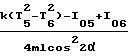
Из системы двух уравнений найдем:
Zl = ![]()
![]()
![]()
![]()
Z l = ![]()
![]()
![]()
![]()
Для того, чтобы определить центральный эллипсоид инерции, определяется сначала эллипсоид инерции изделия в точке, совпадающей с точкой пересечения осей OZ и Б-Б при измерениях с номерами 1 = 1, 6, 7, 8, 9, 10. Определение эллипсоида инерции производится по известной методике после того, как будут найдены коэффициенты уравнения эллипсоида инерции:
Ix x2 + Iy y2 + Iz Z2-2Iyz yz-2 Izx zx-2Ixy xy = 1.In order to determine the central ellipsoid of inertia, the product inertia ellipsoid is first determined at a point that coincides with the intersection point of the OZ and BB axes during measurements with
I x x 2 + I y y 2 + I z Z 2 -2I yz yz-2 I zx zx-2I xy xy = 1.
С помощью теоремы Гюйгенса о параллельных осях найдем выражения для коэффициентов центрального эллипсоида инерции:
Ix l = Ix-m (yl 2 + Z![]()
Iy l = Iy-m (xl 2 + Z![]()
Iy l = Iz-m (xl 2 + yl 3),
Iyz l = Iyz-m yl Zl
Izx l = Izx-m Zl xl,
Ixy l = Ixy-m xl yl.Using the Huygens parallel axis theorem, we find expressions for the coefficients of the central inertia ellipsoid:
I x l = I x -m (y l 2 + Z ![]()
I y l = I y -m (x l 2 + Z ![]()
I y l = I z -m (x l 2 + y l 3 ),
I yz l = I yz -my l Z l
I zx l = I zx -m Z l x l ,
I xy l = I xy -mx l y l .
Окончательно уравнение центрального эллипсоида инерции записывается с учетом зависимостей
Ix lx2 + Iy ly2 + Iz lZ2-2Iyz lyz-2Izx lZx-2Ixy lxy = 1.Finally, the equation of the central ellipsoid of inertia is written taking into account the dependencies
I x l x 2 + I y l y 2 + I z l Z 2 -2I yz l yz-2I zx l Zx-2I xy l xy = 1.
Таким образом, использование предлагаемого устройства для определения инерционных характеристик по сравнению с прототипом позволяет дополнительно определить третью координату центра масс изделия и центральный эллипсоид инерции за счет того, что планшайба устройства выполнена поворотной относительно оси, совпадающей с осью платформы. Между планшайбой и основным узлом поворота размещен дополнительный узел поворота планшайбы относительно наклонной оси, что создает технико-экономический эффект. Thus, the use of the proposed device for determining the inertial characteristics in comparison with the prototype allows you to additionally determine the third coordinate of the center of mass of the product and the central ellipsoid of inertia due to the fact that the faceplate of the device is made rotatable relative to the axis coinciding with the axis of the platform. Between the faceplate and the main turning unit there is an additional turning unit for turning the faceplate relative to the inclined axis, which creates a technical and economic effect.
Claims (1)
Priority Applications (1)
| Application Number | Priority Date | Filing Date | Title |
|---|---|---|---|
| SU4883317 RU2017103C1 (en) | 1990-11-20 | 1990-11-20 | Device for measuring inertial characteristics of articles |
Applications Claiming Priority (1)
| Application Number | Priority Date | Filing Date | Title |
|---|---|---|---|
| SU4883317 RU2017103C1 (en) | 1990-11-20 | 1990-11-20 | Device for measuring inertial characteristics of articles |
Publications (1)
| Publication Number | Publication Date |
|---|---|
| RU2017103C1 true RU2017103C1 (en) | 1994-07-30 |
Family
ID=21545686
Family Applications (1)
| Application Number | Title | Priority Date | Filing Date |
|---|---|---|---|
| SU4883317 RU2017103C1 (en) | 1990-11-20 | 1990-11-20 | Device for measuring inertial characteristics of articles |
Country Status (1)
| Country | Link |
|---|---|
| RU (1) | RU2017103C1 (en) |
Cited By (3)
| Publication number | Priority date | Publication date | Assignee | Title |
|---|---|---|---|---|
| RU2480726C1 (en) * | 2011-11-30 | 2013-04-27 | Федеральное Государственное Унитарное Предприятие "Научно-Производственное Объединение "Техномаш" | Method for determining inertia moments of item, and device for its implementation |
| RU2683800C2 (en) * | 2017-03-31 | 2019-04-02 | Российская Федерация, от имени которой выступает Государственная корпорация по атомной энергии "Росатом" | Complex for determining inertial characteristics with a measuring system |
| RU2697442C2 (en) * | 2017-09-13 | 2019-08-14 | Федеральное государственное унитарное предприятие "Комбинат "Электрохимприбор" (ФГУП "Комбинат "Электрохимприбор") | Device for determining inertial characteristics of elongated articles |
-
1990
- 1990-11-20 RU SU4883317 patent/RU2017103C1/en active
Non-Patent Citations (1)
| Title |
|---|
| Авторское свидетельство СССР N 1130752, кл. G 01M 1/10, 1983. * |
Cited By (3)
| Publication number | Priority date | Publication date | Assignee | Title |
|---|---|---|---|---|
| RU2480726C1 (en) * | 2011-11-30 | 2013-04-27 | Федеральное Государственное Унитарное Предприятие "Научно-Производственное Объединение "Техномаш" | Method for determining inertia moments of item, and device for its implementation |
| RU2683800C2 (en) * | 2017-03-31 | 2019-04-02 | Российская Федерация, от имени которой выступает Государственная корпорация по атомной энергии "Росатом" | Complex for determining inertial characteristics with a measuring system |
| RU2697442C2 (en) * | 2017-09-13 | 2019-08-14 | Федеральное государственное унитарное предприятие "Комбинат "Электрохимприбор" (ФГУП "Комбинат "Электрохимприбор") | Device for determining inertial characteristics of elongated articles |
Similar Documents
| Publication | Publication Date | Title |
|---|---|---|
| Rolland et al. | A survey of tracking technologies for virtual environments | |
| US7640786B2 (en) | Self-calibrating accelerometer | |
| Goodman et al. | Effect of finite rotations on gyroscopic sensing devices | |
| JPH01503335A (en) | Multi-axis angular velocity detector with a single swing axis | |
| CN111678538A (en) | An Error Compensation Method of Dynamic Level Based on Speed Matching | |
| JP4294979B2 (en) | Inertial device misalignment measurement method | |
| CN108917788B (en) | Method and system for testing dynamic precision of accelerometer of inertial platform system | |
| RU2017103C1 (en) | Device for measuring inertial characteristics of articles | |
| Zhuravlev et al. | The generalized Foucault pendulum is a 3D integrating gyroscopes using the three-dimensional precession of standing waves in a rotating spherically symmetric elastic solid | |
| JPH11211474A (en) | Attitude angle detector | |
| US20050217127A1 (en) | Measurement device and method for determining the three-dimensional orientation of a body relative to two horizontal reference directions | |
| JP6477214B2 (en) | Method and apparatus for measuring inclination, electronic device and program | |
| JACKSON | Continuous calibration and alignment techniques for an all-attitude inertial platform | |
| SU481769A1 (en) | The method for determining the latitude of the location | |
| Flynn | A Discussion of Coning Errors Exhibited by Inertial Navigation Systems. | |
| RU2186337C2 (en) | Gear measuring relative angular position of reflectors | |
| SU1046633A1 (en) | Method of determination of central moment of inertia, mass center coordinates in given plane and mass of the body | |
| RU2138018C1 (en) | Process generating navigational parameters and position vertical | |
| Doronin et al. | Operation principle and basic errors of vibratory gyroscopes as rotation angle measuring device | |
| RU23974U1 (en) | MICROMECHANICAL GYROSCOPE | |
| RU2674572C1 (en) | Strapdown inertial navigation system for high-speed maneuvering object | |
| RU2180134C2 (en) | Handler | |
| SU1641457A1 (en) | Vibration transducer | |
| Veškrna | Positioning system for small devices using principles of inertial navigation system | |
| RU2168208C2 (en) | Three-coordinate graphical information handler built around single-coordinate transducers |