RU2015373C1 - Rotary engine with non-circular profile of cross-section - Google Patents
Rotary engine with non-circular profile of cross-section Download PDFInfo
- Publication number
- RU2015373C1 RU2015373C1 SU914920413A SU4920413A RU2015373C1 RU 2015373 C1 RU2015373 C1 RU 2015373C1 SU 914920413 A SU914920413 A SU 914920413A SU 4920413 A SU4920413 A SU 4920413A RU 2015373 C1 RU2015373 C1 RU 2015373C1
- Authority
- RU
- Russia
- Prior art keywords
- shaft
- axis
- cylinder
- cross
- covers
- Prior art date
Links
- 239000000446 fuel Substances 0.000 claims abstract description 7
- 239000007789 gas Substances 0.000 abstract description 6
- 238000007599 discharging Methods 0.000 abstract 1
- 239000000126 substance Substances 0.000 abstract 1
- 239000000203 mixture Substances 0.000 description 4
- 238000002485 combustion reaction Methods 0.000 description 2
- 230000007423 decrease Effects 0.000 description 2
- 230000015556 catabolic process Effects 0.000 description 1
- 238000010835 comparative analysis Methods 0.000 description 1
- 230000006835 compression Effects 0.000 description 1
- 238000007906 compression Methods 0.000 description 1
- 238000010276 construction Methods 0.000 description 1
- 238000001816 cooling Methods 0.000 description 1
- 230000008030 elimination Effects 0.000 description 1
- 238000003379 elimination reaction Methods 0.000 description 1
- 230000003993 interaction Effects 0.000 description 1
- 239000003350 kerosene Substances 0.000 description 1
- 238000005461 lubrication Methods 0.000 description 1
- 230000007257 malfunction Effects 0.000 description 1
- 238000004519 manufacturing process Methods 0.000 description 1
- 239000002184 metal Substances 0.000 description 1
- 210000003739 neck Anatomy 0.000 description 1
- 238000007789 sealing Methods 0.000 description 1
Images


Classifications
-
- Y—GENERAL TAGGING OF NEW TECHNOLOGICAL DEVELOPMENTS; GENERAL TAGGING OF CROSS-SECTIONAL TECHNOLOGIES SPANNING OVER SEVERAL SECTIONS OF THE IPC; TECHNICAL SUBJECTS COVERED BY FORMER USPC CROSS-REFERENCE ART COLLECTIONS [XRACs] AND DIGESTS
- Y02—TECHNOLOGIES OR APPLICATIONS FOR MITIGATION OR ADAPTATION AGAINST CLIMATE CHANGE
- Y02T—CLIMATE CHANGE MITIGATION TECHNOLOGIES RELATED TO TRANSPORTATION
- Y02T10/00—Road transport of goods or passengers
- Y02T10/10—Internal combustion engine [ICE] based vehicles
- Y02T10/12—Improving ICE efficiencies
Landscapes
- Transmission Devices (AREA)
Abstract
Description
Изобретение относится к области двигателестроения, в частности к роторным двигателям. The invention relates to the field of engine construction, in particular to rotary engines.
Известны двигатели, содержащие корпус, эксцентричный вал, входной и выхлопной трубопроводы, свечи зажигания, шестерни внутреннего и внешнего зацепления, системы охлаждения и смазки. Known engines containing a housing, an eccentric shaft, intake and exhaust pipes, spark plugs, gears of internal and external gearing, cooling and lubrication systems.
Недостатки - сложность конструкции, сравнительно большие значения расхода горючего, а также габаритов и массы. Disadvantages - design complexity, relatively large values of fuel consumption, as well as dimensions and mass.
Известна конструкция, содержащая корпус, ротор, коленвал, зубчатое колесо и зубчатый венец ротора, фигурный паз уплотнительные пластины, пружины впускной и выхлопной канал, свечу зажигания. С целью повышения КПД образующая внутренней полосы корпуса и паз в стенке корпуса выполнены по сложным кривым, описываемым многозвенными системами уравнений. A known structure comprising a housing, a rotor, a crankshaft, a gear wheel and a ring gear of a rotor, a shaped groove, sealing plates, inlet and exhaust channel springs, and a spark plug. In order to increase the efficiency, the generatrix of the inner strip of the body and the groove in the wall of the body are made according to complex curves described by multi-link systems of equations.
Недостатки - сложность конструкции, большие значения габаритов массы и расхода горючего, а также сложность технологического изготовления. Disadvantages - the complexity of the design, the large values of the dimensions of the mass and fuel consumption, as well as the complexity of the manufacturing process.
В качестве прототипа выбрано устройство, содержащее корпус, образующая которого выполнена на конхоиде, эксцентрично установленный ротор со сквозными пазами, в которых размещены лопатки, связанные с коленчатым валом, синхронизирующий механизм, включающий зубчатые колеса жестко установленные на шейках коленчатых валов и связанные с центральным зубчатым колесом, установленным на корпусе. As a prototype, a device is selected that contains a housing, the generatrix of which is made on a conchoid, an eccentrically mounted rotor with through grooves, in which blades are connected associated with the crankshaft, a synchronization mechanism including gears rigidly mounted on the necks of the crankshafts and connected to the central gear wheel mounted on the case.
Недостатки прототипа - сравнительно низкий КПД, сложность конструкции и низкая надежность. The disadvantages of the prototype are relatively low efficiency, design complexity and low reliability.
Цель изобретения - упрощение конструкции, повышение надежности и КПД. The purpose of the invention is to simplify the design, increase reliability and efficiency.
Указанная цель достигается тем, что в лопастном роторном двигателе, содержащем цилиндр, боковые крышки, вал, ось которого параллельна оси цилиндра и смещена относительно нее, барабан, жестко закрепленный на валу с направляющими для лопаток, в плоскостях которых находится ось вала, свечи, отверстия для подачи топлива и выхода отработанных газов. На кромке каждой из лопаток или вблизи ее со стороны вала закреплены по ее бокам пальцы с роликами, входящими в кольцевые пазы на боковых крышках с центром этих кольцевых пазов на оси цилиндра. Средняя линия каждого из кольцевых пазов выполнена в виде окружности с радиусом r с центром, отнесенным от оси вала на расстояние С. Профиль поперечного сечения цилиндра описывается уравнением
ζ= a+c cosα+![]()
ζ = a + c cosα + ![]()
Сопоставительный анализ с прототипом показывает, что указанное техническое решение отличается тем, что на кромке каждой из лопаток или вблизи ее со стороны вала закреплены по ее бокам пальцы с роликами входящими в кольцевые пазы на боковых крышках с центром этих кольцевых пазов на оси цилиндра. Средняя линия каждого из кольцевых пазов выполнена в виде окружности с радиусом r с центром, отнесенным от оси вала на расстояние С, а профиль поперечного сечения цилиндра описывается уравнением
ζ= a+c cosα+![]()
ζ = a + c cosα + ![]()
Таким образом, заявляемое техническое решение отвечает критерию "новизна". Thus, the claimed technical solution meets the criterion of "novelty."
Сравнение указанного технического решения не только с прототипом, но и с другими техническими решениями в данной области не позволили выявить в них признаки, отличающие его от прототипа, что позволяет сделать вывод о соответствии критерию "существенные отличия". Comparison of the indicated technical solution not only with the prototype, but also with other technical solutions in this area did not allow us to identify in them the features that distinguish it from the prototype, which allows us to conclude that the criterion of "significant differences" is met.
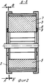
На фиг. 1 - разрез А-А на фиг. 2; на фиг. 2 - разрез Б-Б на фиг. 1; на фиг. 3 - разрез В-В на фиг. 2; на фиг. 4 - узел лопатки с пальцем и роликом; на фиг. 5 - лопастной двигатель, аксонометрия; на фиг. 6 - вал с барабаном, аксонометрия. In FIG. 1 is a section AA in FIG. 2; in FIG. 2 - section BB in FIG. 1; in FIG. 3 is a section BB of FIG. 2; in FIG. 4 - blade assembly with a finger and a roller; in FIG. 5 - blade engine, axonometry; in FIG. 6 - shaft with a drum, axonometry.
Устройство содержит цилиндр 1 с крышками 2 и 3, вал 4, барабан 5 с направляющими 6, в которые входят лопатки 7, имеющие пальцы 8 с роликами 9 и подпружиненными вкладышами 10. Имеются отверстия 11 и 12 для подачи топлива и воздуха под давлением и свеча 13, а также отверстия 14 в крышках 2 и 3 для вала 4. На каждой крышке 2 и 3 имеется кольцевой паз 15 для вхождения в него пальцев 8 с роликами 9, при этом центр кольцевого паза находится на оси цилиндра. Для выхлопа газов имеется отверстие 16. Для обеспечения более полного сгорания смеси свечи 13 могут быть дополнительно поставлены и в соседней камере по ходу движения вала 4. The device comprises a
Через каналы 12 и 11 в камеру подаются соответственно воздух под давлением и газ (или пары бензина, керосина и др.). Through
При повороте вала 4 против часовой стрелки происходит сжатие, и в дальнейшем сжатая смесь зажигается свечой 13. When the
Ввиду разности площадей лопаток 7, ограничивающих камеру, где находится свеча 13, вал 4 с барабаном 5 под давлением вспыхнувших газов будут продолжать вращение против часовой стрелки с дальнейшим выхлопом отработанных газов через канал 16 с последующей подачей воздуха и горючей смеси соответственно через каналы 12 и 11. После этого цикл повторяется. Исключение многочисленных сложных элементов, уменьшение числа деталей и простота их взаимодействия приводят к упрощению конструкции, снижению металлоемкости и габаритов, а также к повышению надежности. Расход горючего уменьшается за счет более полного сгорания смеси в соседних камерах по мере поворота вала 4. Движение пальца 8 с роликом 9 по кольцевому пазу, выполненному в виде окружности снижает наличие перегрузок на лопатках и других элементах кинематики. Due to the difference in the areas of the
Кроме того, соблюдение приведенной зависимости ζ = ζ (r, a, c, α) обеспечивает постоянный минимально-допустимый зазор δ между лопаткой и внутренней стенкой цилиндра, повышает КПД и надежность. In addition, compliance with the given dependence ζ = ζ (r, a, c, α) provides a constant minimum allowable gap δ between the blade and the inner wall of the cylinder, increases efficiency and reliability.
При выполнении профиля поперечного сечения цилиндра по любому другому закону, устанавливающему связь между параметрами ζ, r, a, c, α и отличающемуся от указанного в данном техническом решении, приводит к большим значениям зазора δ, которые могут достигать до 10 мм и более, что повлечет за собой не только нарушение работоспособности или поломку устройства, но и снижение безопасности его применения. When performing the profile of the cylinder cross section according to any other law that establishes a relationship between the parameters ζ, r, a, c, α and differs from that specified in this technical solution, it leads to large values of the gap δ, which can reach up to 10 mm or more, which will entail not only a malfunction or breakdown of the device, but also a decrease in the safety of its use.
Изобретение наиболее эффективно может быть использовано для крупногабаритных двигателей. The invention can most effectively be used for large engines.
Claims (1)
ζ = a+C·cosα+
где ζ - расстояние от оси вала до внутренней стенки цилиндра;
a - расстояние между осью пальца и внутренней стенкой цилиндра в направлении величины ζ под углом α от вертикальной плоскости;
Z - радиус средней линии кольцевого паза, соответствующая траектории движения оси пальца;
C - эксцентриситет расположения вала и кольцевого паза.VALVE ENGINE WITH A NON-CIRCULAR CROSS-SECTION PROFILE, comprising a cylinder body, side covers, a shaft whose axis is parallel offset from the cylinder axis, a drum rigidly mounted on the shaft and having guides for vanes whose plane of intersection of the shaft axis and spark plugs, openings for supplying fuel and exhaust gas are made in the housing, on the lateral edge of each of the blades from its side close to the shaft axis, fingers are fixed with rollers kinematically connected to the ring grooves on the covers, the centers of which are aligned with the cylinder, characterized in that the cross-sectional profile of the cylinder is described by the equation
ζ = a + C cosα +
where ζ is the distance from the axis of the shaft to the inner wall of the cylinder;
a is the distance between the axis of the finger and the inner wall of the cylinder in the direction of ζ at an angle α from the vertical plane;
Z is the radius of the midline of the annular groove corresponding to the trajectory of the axis of the finger;
C is the eccentricity of the location of the shaft and the annular groove.
Priority Applications (1)
| Application Number | Priority Date | Filing Date | Title |
|---|---|---|---|
| SU914920413A RU2015373C1 (en) | 1991-03-21 | 1991-03-21 | Rotary engine with non-circular profile of cross-section |
Applications Claiming Priority (1)
| Application Number | Priority Date | Filing Date | Title |
|---|---|---|---|
| SU914920413A RU2015373C1 (en) | 1991-03-21 | 1991-03-21 | Rotary engine with non-circular profile of cross-section |
Publications (1)
| Publication Number | Publication Date |
|---|---|
| RU2015373C1 true RU2015373C1 (en) | 1994-06-30 |
Family
ID=21565742
Family Applications (1)
| Application Number | Title | Priority Date | Filing Date |
|---|---|---|---|
| SU914920413A RU2015373C1 (en) | 1991-03-21 | 1991-03-21 | Rotary engine with non-circular profile of cross-section |
Country Status (1)
| Country | Link |
|---|---|
| RU (1) | RU2015373C1 (en) |
-
1991
- 1991-03-21 RU SU914920413A patent/RU2015373C1/en active
Non-Patent Citations (4)
| Title |
|---|
| Авторское свидетельство СССР N 1451305, кл. F 02B 53/00, 1989. * |
| Авторское свидетельство СССР N 1518550, кл. F 02B 53/00, 1989. * |
| Патент США N 3486487, кл. F 02B 53/00, 1969. * |
| Романов Б.А. Двигатели внутреннего сгорания. М.: Недра, 1989. * |
Similar Documents
| Publication | Publication Date | Title |
|---|---|---|
| US7614382B2 (en) | Aspiration plate for planetary rotary internal combustion engine | |
| US4072132A (en) | Rotary internal combustion engine | |
| US5352295A (en) | Rotary vane engine | |
| CA2844015A1 (en) | Rotary internal combustion engine with pilot subchamber | |
| RU2148721C1 (en) | Axial rotary engine | |
| JP2011247268A (en) | Rotary combustion apparatus | |
| CA2782745C (en) | Apex seal arrangement for rotary internal combustion engine | |
| US4572121A (en) | Rotary vane type I.C. engine with built-in scavenging air blower | |
| RU2015373C1 (en) | Rotary engine with non-circular profile of cross-section | |
| RU2015374C1 (en) | Rotary-vane engine | |
| RU2619672C1 (en) | Six-stroke rotary-vane internal combustion engine | |
| RU2158375C1 (en) | Rotary piston internal combustion engine | |
| RU2400640C2 (en) | Internal combustion engine | |
| RU2272164C2 (en) | Rotary internal combustion engine | |
| RU2078957C1 (en) | Rotary internal combustion engine | |
| RU2271457C1 (en) | Rotary-piston internal combustion engine | |
| RU2044902C1 (en) | Rotor internal combustion engine | |
| RU2444635C2 (en) | Rotary engine | |
| RU2418180C1 (en) | Rotary engine and cam shaft | |
| US4227506A (en) | Internal combustion engine | |
| RU199412U1 (en) | ROTARY FOUR-STROKE INTERNAL COMBUSTION ENGINE "ROLAN" | |
| GB1573552A (en) | Rotary internal combustion engine | |
| RU41083U1 (en) | GALANIAN ROTOR-PISTON ENGINE | |
| RU2246015C2 (en) | Rotary internal combustion engine | |
| RU2415285C2 (en) | Rotary engine |