RU2013802C1 - Generator of pseudorandom sequences of binary numbers - Google Patents
Generator of pseudorandom sequences of binary numbers Download PDFInfo
- Publication number
- RU2013802C1 RU2013802C1 SU5014945A RU2013802C1 RU 2013802 C1 RU2013802 C1 RU 2013802C1 SU 5014945 A SU5014945 A SU 5014945A RU 2013802 C1 RU2013802 C1 RU 2013802C1
- Authority
- RU
- Russia
- Prior art keywords
- input
- generator
- digit
- elements
- inputs
- Prior art date
Links
Images
Landscapes
- Feedback Control In General (AREA)
Abstract
Description
Изобретение относится к вычислительной и информационной технике и может быть использовано при решении задач статистического моделирования на ЭВМ, а также в различных кодирующих устройствах, использующих некоррелированные псевдослучайные последовательности двоичных чисел. The invention relates to computing and information technology and can be used in solving problems of statistical modeling on a computer, as well as in various coding devices using uncorrelated pseudorandom sequences of binary numbers.
Известен рекурентный вероятностный преобразователь потока псевдослучайных двоичных чисел [1] , содержащий поочередно подключаемые на случайные интервалы времени управляемые датчики потоков случайных импульсов ДПСИ. A recurrent probabilistic pseudorandom binary number stream converter [1] is known that contains controllable sensors of random impulse flows of DPSIs, connected alternately at random time intervals.
Недостатком таких устройств является наличие в них большого числа управляемых ДПСИ или генераторов импульсов. The disadvantage of such devices is the presence in them of a large number of controlled DPSI or pulse generators.
Наиболее близким к рассматриваемому является датчик последовательностей псевдослучайных чисел на основе регистра сдвига с сумматором по модулю два в обратной связи [2] . Closest to the considered one is a pseudorandom number sequence sensor based on a shift register with an adder modulo two in feedback [2].
Недостатком их является наличие корреляционной зависимости в генерируемых двоичных числах из-за конечности максимального периода М при повторяемости циклов. Their disadvantage is the presence of a correlation dependence in the generated binary numbers due to the finiteness of the maximum period M with cycle repeatability.
Изобретение лишено перечисленных недостатков. The invention is devoid of the above disadvantages.
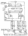
На чертеже приведена блок-схема предлагаемого генератора псевдослучайных последовательностей двоичных чисел. The drawing shows a block diagram of the proposed generator of pseudo-random sequences of binary numbers.
Генератор работает следующим образом. С генератора тактовых импульсов 1 на входы разрядных ячеек К разрядного регистра 2 с сумматором по мод. 2 в цепи обратной связи заносится короткое К-разрядное двоичное число. По сигналу "Пуск" триггер 3 "Пуск" устанавливается в единичное состояние, включая разрешающий потенциал на вторых входах элементов И 4 и 5. На первый вход элемента И 4 поступают тактовые импульсы с генератора 1 тактовых импульсов, которые проходят на вход последовательного сдвига К-разрядного регистра 2 сдвига. С выхода К-разрядного регистра 2 сдвига последовательность псевдослучайных двоичных чисел поступает на первый вход элемента И 5, которая при наличии разрешающего потенциала на его втором входе поступает на вход Р разрядного счетчика "единиц", следующих с переменной скважностью, и одновременно на вторые входы m элементов И 8. При заполнении Р-разрядного 6 счетчика "единиц" на его выходе с интервалами случайной длительности t ± Δ t, определяемыми дисперсией количества "единиц", поступающих в счетчик, вырабатывается импульс сброса счетчика, поступающий на вход управления сдвигом m разрядного кольцевого 7 переключателя, при переключении ячеек которого на первых входах элементов И 8 на время случайного интервала t ± Δ t устанавливаются поочередно разрешающие потенциалы, по которым на выходы соответствующих элементов И 8 в соответствии с наличием разрешающего потенциала на его входе поочередно проходят серии импульсов псевдослучайной последовательности для первоначального заполнения m независимых регистров 9 сдвига с сумматором по мод. 2 в цепи обратной связи. С выходов mni разрядных регистров 9 сдвига псевдослучайные последовательности двоичных чисел поступают на первые входы соответствующих элементов И 10, на вторые входы которых поступают поочередно разрешающие потенциалы с возбужденных ячеек m разрядного 13 кольцевого переключателя. Длительность разрешающего потенциала на входе элементов И 10 случайна, так как определяется интервалом случайной длительности t1 ± Δ t, с которым следуют импульсы сброса при переполнении l-разрядного счетчика 1 2"единиц", вырабатываемых соответствующим регистром 9 сдвига, подключаемым в данный момент к входу элемента ИЛИ 11. Псевдослучайная последовательность двоичных чисел с выхода элемента ИЛИ 11, являющегося выходным элементом генератора, поступает на выход генератора и одновременно на вход l-разрядного счетчика 12 единиц. При заполнении l-разрядного счетчика 12 единиц на его выходе с интервалом случайной длительности t ± Δ t, определяемым дисперсией количества "единиц", требующихся для заполнения счетчика, вырабатывается импульс переполнения счетчика, поступающий на вход управления сдвигом m-разрядного кольцевого 13 переключателя. При переключении m-разрядного 13 переключателя на вторых входах элементов И 10 поочередно устанавливается разрешающий потенциал случайной деятельности t1± Δ t, разрешающий прохождение "единиц" и "нулей" вырабатываемой последовательности соответствующего регистра 9 на вход элемента ИЛИ 11 и на выход генератора. В результате на выходе m-входного элемента ИЛИ 11 образуется некоррелированная псевдослучайная последовательность двоичных чисел, составленная из серии псевдослучайных двоичных чисел, вырабатываемых m независимыми ni разрядными регистрами 9 сдвига максимального периода при их периодическом первоначальном заполнении случайными двоичными числами, вырабатываемыми К-разрядным регистром 2 сдвига максимального периода.The generator operates as follows. From the
Техническая эффективность предлагаемого генератора определяется повышением скорости выработки некоррелированных псевдослучайных последовательностей двоичных чисел за счет использования для первоначальной записи ni разрядных двоичных чисел в m регистров сдвига короткого К-разрядного ( K < min ni) случайного числа и его автоматического преобразования в m, ni-разрядные псевдослучайные двоичные числа для первоначальной записи в m-независимые регистры сдвига максимального периода.The technical efficiency of the proposed generator is determined by increasing the speed of generating uncorrelated pseudorandom sequences of binary numbers due to the use of a short K-bit (K <min n i ) random number shift register and its automatic conversion to m, n i for initial recording of n i bit binary numbers in m -bit pseudo-random binary numbers for initial recording in m-independent shift registers of the maximum period.
Claims (1)
Priority Applications (1)
| Application Number | Priority Date | Filing Date | Title |
|---|---|---|---|
| SU5014945 RU2013802C1 (en) | 1991-11-05 | 1991-11-05 | Generator of pseudorandom sequences of binary numbers |
Applications Claiming Priority (1)
| Application Number | Priority Date | Filing Date | Title |
|---|---|---|---|
| SU5014945 RU2013802C1 (en) | 1991-11-05 | 1991-11-05 | Generator of pseudorandom sequences of binary numbers |
Publications (1)
| Publication Number | Publication Date |
|---|---|
| RU2013802C1 true RU2013802C1 (en) | 1994-05-30 |
Family
ID=21590758
Family Applications (1)
| Application Number | Title | Priority Date | Filing Date |
|---|---|---|---|
| SU5014945 RU2013802C1 (en) | 1991-11-05 | 1991-11-05 | Generator of pseudorandom sequences of binary numbers |
Country Status (1)
| Country | Link |
|---|---|
| RU (1) | RU2013802C1 (en) |
Cited By (2)
| Publication number | Priority date | Publication date | Assignee | Title |
|---|---|---|---|---|
| WO2000039667A1 (en) * | 1998-12-25 | 2000-07-06 | Samsung Electronics Company, Limited | Code generator |
| CN103617020A (en) * | 2013-12-23 | 2014-03-05 | 乐得科技有限公司 | Method and equipment for generating random number in application program |
-
1991
- 1991-11-05 RU SU5014945 patent/RU2013802C1/en active
Cited By (3)
| Publication number | Priority date | Publication date | Assignee | Title |
|---|---|---|---|---|
| WO2000039667A1 (en) * | 1998-12-25 | 2000-07-06 | Samsung Electronics Company, Limited | Code generator |
| CN103617020A (en) * | 2013-12-23 | 2014-03-05 | 乐得科技有限公司 | Method and equipment for generating random number in application program |
| CN103617020B (en) * | 2013-12-23 | 2018-03-23 | 网易乐得科技有限公司 | A kind of method and apparatus that random number is generated in application program |
Similar Documents
| Publication | Publication Date | Title |
|---|---|---|
| RU2013802C1 (en) | Generator of pseudorandom sequences of binary numbers | |
| RU2081450C1 (en) | Generator of n-bit random sequence | |
| SU497718A1 (en) | Device for generating pseudo-random signals of complex structure | |
| SU781798A1 (en) | Generator of uniformly-distributed random signals | |
| RU2080651C1 (en) | Generator of random n-bit binary numbers | |
| RU2092892C1 (en) | Uniform distribution random number generator | |
| SU1272342A1 (en) | Device for calculating value of exponent of exponential function | |
| SU739602A1 (en) | Pseudorandom number generator | |
| SU1257815A1 (en) | Device for generating shifted copies of pseudorandom sequences | |
| SU1179335A1 (en) | Quasi-stochastic converter | |
| SU1101804A1 (en) | Stochastic walsh function generator | |
| SU930310A1 (en) | Readjustable structure code sequence generator | |
| SU703852A1 (en) | Pseudorandom number generator | |
| SU871314A2 (en) | Discrete matched filter | |
| RU2120179C1 (en) | White noise generator ( variants ) | |
| SU943720A1 (en) | Pseudo-random pulse train generator | |
| SU1522411A1 (en) | Binary-to-binary-decimal code converter | |
| SU903874A1 (en) | Pseudorandom number generator | |
| SU1142837A1 (en) | Device for checking logic units | |
| SU1020821A1 (en) | Pseudorandom sequence generator | |
| SU1170453A1 (en) | Test sequence generator | |
| SU1070531A1 (en) | Walsh function generator | |
| RU1783616C (en) | Converter of fibonachi code to golden proportion cod | |
| SU1709530A1 (en) | Code-to-frequency converter | |
| SU984001A1 (en) | Generator of pseudorandom pulse trains |