RU2006373C1 - Rail vehicle flexible wheel - Google Patents
Rail vehicle flexible wheel Download PDFInfo
- Publication number
- RU2006373C1 RU2006373C1 SU4929905A RU2006373C1 RU 2006373 C1 RU2006373 C1 RU 2006373C1 SU 4929905 A SU4929905 A SU 4929905A RU 2006373 C1 RU2006373 C1 RU 2006373C1
- Authority
- RU
- Russia
- Prior art keywords
- wheel
- rail vehicle
- center
- hub
- elements
- Prior art date
Links
Images
Landscapes
- Railway Tracks (AREA)
Abstract
Description
Изобретение относится к средствам рельсового транспорта, а точнее к колесам рельсовых транспортных средств. The invention relates to means of rail transport, and more specifically to the wheels of rail vehicles.
Известно упругое колесо рельсового транспортного средства, содержащее центр, обод, детали крепления, резиновый бандаж с размещенным на нем упругим кольцом с отверстиями, в которые входят шипы резинового бандажа. A resilient wheel of a rail vehicle is known, comprising a center, a rim, fasteners, a rubber band with an elastic ring disposed thereon with holes in which spikes of the rubber band are included.
В таком колесе ступица относительно оси насажена жестко, что не обеспечивает компенсацию сил, действующих на подшипниковый узел, обусловленных несовершенствами рельсового пути, что снижает надежность работы и обуславливает существенные динамические нагрузки. In such a wheel, the hub is rigidly mounted relative to the axis, which does not compensate for the forces acting on the bearing assembly due to imperfections in the track, which reduces the reliability of operation and causes significant dynamic loads.
Известно также упругое колесо рельсового транспортного средства, содержащее обод с ребордой, диск, ступицу и соединенные между собой втулки с внешними поверхностями, сопряженными с соответствующими упругими элементами. An elastic wheel of a rail vehicle is also known, comprising a rim with a flange, a disk, a hub, and bushes connected to each other with external surfaces mating with corresponding elastic elements.
В таком колесе упругие элементы не обеспечивают угловое движение центра относительно элементов втулок и подшипникового узла, что снижает надежность и долговечность работы колеса. In such a wheel, the elastic elements do not provide the angular movement of the center relative to the elements of the bushings and the bearing assembly, which reduces the reliability and durability of the wheel.
Цель изобретения - повышение надежности за счет обеспечения поперечной и угловой податливости и уменьшения нагрузок на подшипниковый узел. The purpose of the invention is to increase reliability by providing lateral and angular compliance and reduce the load on the bearing assembly.
Поставленная цель достигнута тем, что внутренняя поверхность ступицы выполнена с двумя коническими участками и сопряжена ими с соответствующими упругими элементами. The goal is achieved in that the inner surface of the hub is made with two conical sections and mated with the corresponding elastic elements.
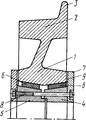
На чертеже показан частичный диаметральный разрез колеса. The drawing shows a partial diametrical section of the wheel.
Упругое колесо рельсового транспортного средства состоит из центра 1, обода 2 с ребордой 3, деталей разрезной биконической втулки 4 и 5. Упругие элементы 6, детали втулки и фиксирующие крышки 7 соединены между собой болтами 8. Фиксирующие крышки относительно торцов центра колеса установлены с зазорами 9 так, чтобы при упругих элементах, затянутых элементами втулки, они обеспечивали поперечные и угловые движения центра относительно элементов втулок и подшипникового узла (условно не показан). The elastic wheel of a rail vehicle consists of a center 1, a
Колесо собирают в такой последовательности. The wheel is assembled in this order.
В отверстие центра 1 устанавливают упругие элементы 6, затем заводят в это отверстие со стороны торцов центра детали разрезной биконической втулки 4, 5, внешние поверхности которых сопряжены с соответствующими упругими элементами, приставляют фиксирующие крышки 7 и стягивают болтами 8 до установленной на стенде величины, при которой исключается проворот центра относительно элементов втулки. Но при этом должны быть сохранены зазоры 9. In the hole in the center 1,
Далее собранное таким образом колесо устанавливают на подшипники, размещенные на опорном участке оси. Центр такого колеса, благодаря выполнению внутренней поверхности ступицы с двумя коническими участками и сопряжению ими с соответствующими упругими элементами, при движении транспортного средства по рельсовому пути с несовершенствами под действием вертикальной и поперечной составляющей будет совершать вертикальные и угловые колебания без поперечных перемещений обода относительно головки рельса, что уменьшает динамические нагрузки и износ и повышает долговечность работы колеса. (56) Заявка ФРГ N 2545032, кл. В 60 В 9/12, 1988. Next, the wheel thus assembled is mounted on bearings located on the axle bearing portion. The center of such a wheel, due to the implementation of the inner surface of the hub with two conical sections and their conjugation with the corresponding elastic elements, when the vehicle moves along the rail track with imperfections under the action of the vertical and transverse components, it will perform vertical and angular vibrations without lateral movements of the rim relative to the rail head, which reduces dynamic loads and wear and increases the durability of the wheel. (56) Application of Germany N 2545032, CL B 60
Claims (1)
Priority Applications (1)
| Application Number | Priority Date | Filing Date | Title |
|---|---|---|---|
| SU4929905 RU2006373C1 (en) | 1991-04-19 | 1991-04-19 | Rail vehicle flexible wheel |
Applications Claiming Priority (1)
| Application Number | Priority Date | Filing Date | Title |
|---|---|---|---|
| SU4929905 RU2006373C1 (en) | 1991-04-19 | 1991-04-19 | Rail vehicle flexible wheel |
Publications (1)
| Publication Number | Publication Date |
|---|---|
| RU2006373C1 true RU2006373C1 (en) | 1994-01-30 |
Family
ID=21571098
Family Applications (1)
| Application Number | Title | Priority Date | Filing Date |
|---|---|---|---|
| SU4929905 RU2006373C1 (en) | 1991-04-19 | 1991-04-19 | Rail vehicle flexible wheel |
Country Status (1)
| Country | Link |
|---|---|
| RU (1) | RU2006373C1 (en) |
-
1991
- 1991-04-19 RU SU4929905 patent/RU2006373C1/en active
Similar Documents
| Publication | Publication Date | Title |
|---|---|---|
| US5564521A (en) | Torque rod assembly | |
| US6652043B2 (en) | Reduced sound transmitting idler for track-type vehicles | |
| US5493755A (en) | Shock and vibration isolating caster suspension | |
| US4585431A (en) | Sprocket assembly for a track type vehicle | |
| CA1311945C (en) | Sprocket assembly | |
| US2674330A (en) | Propeller shaft support having yieldable connection with chassis frame | |
| US5785395A (en) | Cushioned roller for a belted undercarriage | |
| RU2006373C1 (en) | Rail vehicle flexible wheel | |
| US3504951A (en) | Endless track | |
| DK161370C (en) | WHEEL HIRE IS FOR TOYS | |
| US4515573A (en) | Differential coupling | |
| CN110962502B (en) | Elastic wheel for railway vehicle, use method of elastic wheel and independent wheel set | |
| US2516896A (en) | Wheel structure | |
| GB2082525A (en) | A wheel, preferably for a tracked vehicle, elastically arranged on a wheel hub | |
| US3951783A (en) | Face seal for spherical surface | |
| US3759586A (en) | Endless track pin assembly | |
| RU2009896C1 (en) | Automobile wheel unit | |
| RU2097236C1 (en) | Axle-box unit | |
| SU1594119A1 (en) | Crane wheel | |
| RU1794693C (en) | Flexible wheel of rail vehicle | |
| US5791256A (en) | Axle sprung motor | |
| SU1659233A1 (en) | Device for connecting vehicle frame to wheel | |
| RU2102250C1 (en) | Variable geometry drive | |
| SU893590A1 (en) | Raiway vehicle wheeled pair | |
| SU1685757A2 (en) | Wheel |