RU166326U1 - SHIP'S ENERGY SAVING INSTALLATION - Google Patents
SHIP'S ENERGY SAVING INSTALLATION Download PDFInfo
- Publication number
- RU166326U1 RU166326U1 RU2016119864/11U RU2016119864U RU166326U1 RU 166326 U1 RU166326 U1 RU 166326U1 RU 2016119864/11 U RU2016119864/11 U RU 2016119864/11U RU 2016119864 U RU2016119864 U RU 2016119864U RU 166326 U1 RU166326 U1 RU 166326U1
- Authority
- RU
- Russia
- Prior art keywords
- ship
- channel
- evaporator
- energy
- boiler
- Prior art date
Links
- 238000009434 installation Methods 0.000 title claims abstract description 23
- 239000002826 coolant Substances 0.000 claims abstract description 25
- 239000000126 substance Substances 0.000 claims abstract description 20
- 238000009835 boiling Methods 0.000 claims abstract description 12
- 239000013535 sea water Substances 0.000 claims abstract description 12
- 238000001704 evaporation Methods 0.000 claims abstract description 9
- 230000008020 evaporation Effects 0.000 claims abstract description 9
- 239000007788 liquid Substances 0.000 claims abstract description 9
- 238000010521 absorption reaction Methods 0.000 claims abstract description 7
- 238000005057 refrigeration Methods 0.000 claims abstract description 7
- 238000009833 condensation Methods 0.000 claims abstract description 6
- 230000005494 condensation Effects 0.000 claims abstract description 6
- XLYOFNOQVPJJNP-UHFFFAOYSA-N water Substances O XLYOFNOQVPJJNP-UHFFFAOYSA-N 0.000 claims abstract description 6
- 238000011084 recovery Methods 0.000 claims abstract description 5
- 230000005611 electricity Effects 0.000 abstract description 15
- 238000006243 chemical reaction Methods 0.000 abstract description 4
- 239000000446 fuel Substances 0.000 abstract description 4
- 238000001816 cooling Methods 0.000 abstract description 2
- 230000015572 biosynthetic process Effects 0.000 abstract 1
- 239000007789 gas Substances 0.000 description 6
- 239000003990 capacitor Substances 0.000 description 4
- 239000002699 waste material Substances 0.000 description 2
- 230000005540 biological transmission Effects 0.000 description 1
- 244000309464 bull Species 0.000 description 1
- 238000002485 combustion reaction Methods 0.000 description 1
- 238000010586 diagram Methods 0.000 description 1
- 238000004519 manufacturing process Methods 0.000 description 1
- 239000000463 material Substances 0.000 description 1
- 230000001105 regulatory effect Effects 0.000 description 1
- 230000001131 transforming effect Effects 0.000 description 1
- 238000009834 vaporization Methods 0.000 description 1
- 230000008016 vaporization Effects 0.000 description 1
Images
Classifications
-
- B—PERFORMING OPERATIONS; TRANSPORTING
- B63—SHIPS OR OTHER WATERBORNE VESSELS; RELATED EQUIPMENT
- B63H—MARINE PROPULSION OR STEERING
- B63H23/00—Transmitting power from propulsion power plant to propulsive elements
- B63H23/22—Transmitting power from propulsion power plant to propulsive elements with non-mechanical gearing
- B63H23/24—Transmitting power from propulsion power plant to propulsive elements with non-mechanical gearing electric
Landscapes
- Chemical & Material Sciences (AREA)
- Engineering & Computer Science (AREA)
- Combustion & Propulsion (AREA)
- Mechanical Engineering (AREA)
- Ocean & Marine Engineering (AREA)
- Engine Equipment That Uses Special Cycles (AREA)
Abstract
Полезная модель относится к судостроению, в частности к электроэнергетическим установкам маломерных судов Речного флота.The utility model relates to shipbuilding, in particular to the power plants of small vessels of the River Fleet.
Судовая энергосберегающая установка (СЭУ) содержит утилизационный котел, главный судовой котел (ГСК), турбину с низкокипящим веществом и систему охлаждения. При этом низкокипящее вещество циркулирует по замкнутому контуру, включающего испаритель, пароперегреватель, турбину, конденсатор, циркуляционный насос, дроссельный вентиль и элементы автоматики.The ship energy-saving installation (SEU) contains a recovery boiler, a main ship boiler (HSC), a low-boiling-water turbine and a cooling system. In this case, the low-boiling substance circulates in a closed circuit, including an evaporator, superheater, turbine, condenser, circulation pump, throttle valve and automation elements.
Таким образом, в СЭУ используется силовая установка, состоящая из турбины с низкокипящим рабочим веществом, испарителя и конденсатора, при этом рабочее вещество испаряется в испарителе за счет утилизации тепловой энергии главной судовой дизельной установки, использования тепловой энергии накопительной емкости и главного судового котла, поступающей в испаритель через теплоноситель, испарение рабочего вещества происходит в теплообменнике, одной полостью которого является испаритель, а в другой полости проходит теплоноситель, нагретый судовыми котлами судовой энергетической установки и накопительной емкости. Конденсатором является другой теплообменник, в одной полости которого проходит отработавший пар, а в другой - охладитель, который отбирает теплоту у отработавшего пара, превращая его в жидкость, охладителем является забортная вода с температурой 7-8°С в осенне-зимнее время, а в весенне-летнее время указанная забортная вода дополнительно охлаждается до температуры 7-8°С в холодильнике абсорбционной холодильной установки данной системы. В результате всего этого будет обеспечен довольно высокий перепад температур испарения и конденсации рабочего вещества соответственно и довольно высокий КПД преобразования тепловой энергии судовых котлов, что приводит к повышению топливной экономичности и КПД судовой энергетической установки.Thus, a power plant consisting of a turbine with a low boiling working substance, an evaporator and a condenser is used in the SEU, while the working substance is evaporated in the evaporator due to the utilization of the thermal energy of the main marine diesel installation, the use of thermal energy of the storage tank and the main marine boiler supplied to the evaporator through the coolant, the evaporation of the working substance takes place in a heat exchanger, one cavity of which is the evaporator, and the heated coolant passes in the other cavity ship boilers of a ship power plant and storage capacity. The condenser is another heat exchanger, in one cavity of which the spent steam passes, and in the other - a cooler that takes heat from the exhaust steam, turning it into liquid, the cooler is outside water with a temperature of 7-8 ° C in autumn and winter, and in spring-summer time, the specified seawater is additionally cooled to a temperature of 7-8 ° C in the refrigerator of an absorption refrigeration unit of this system. As a result of all this, a rather high differential temperature of evaporation and condensation of the working substance will be ensured, respectively, and a rather high efficiency of conversion of thermal energy of ship boilers, which will lead to an increase in fuel economy and efficiency of a ship power plant.
Если судно на длительное время становится на якорь, например в ожидании выгрузки. При этом в зависимости от времени года эксплуатации может быть выполнены два варианта.If the ship anchors for a long time, for example, while waiting for unloading. In this case, depending on the season of operation, two options can be performed.
1 вариант. Судно эксплуатируется в летнее время, главный судовой котел находиться в выключенном состоянии. В этом случае останавливается главный судовой дизель и запускается дизель-генератор. Начинается выработка электроэнергии для питания судовых потребителей.1 option. The ship is operated in the summer, the main ship's boiler is in the off state. In this case, the main marine diesel engine stops and the diesel generator starts. Generation of electricity for supplying ship consumers begins.
2 вариант. Судно эксплуатируется в осенне-зимнее время, ГСК 21 находится в рабочем состоянии. При этом заявляемая энергосберегающая установка после остановки дизеля будет обслуживаться от ГСК. И будет вырабатываться электроэнергия.Option 2. The vessel is operated in the autumn-winter time, GSK 21 is in working condition. In this case, the inventive energy-saving installation after stopping the diesel engine will be serviced by GSK. And electricity will be generated.
Таким образом, данная заявка «Энергосберегающая установка речного судна» позволяет получить новую судовую электроэнергетическую установку, обеспечивающую электроэнергией все судовые потребители, экономичное расходование топлива, а также увеличить ресурс дизель-генератора. Внедрение устройства будет способствовать получению значительного экономического эффекта и формированию комплексных систем автоматизации судов Речного флота. Thus, this application “Energy-saving installation of a river vessel” allows you to get a new ship electric power plant that provides electricity to all ship consumers, economical fuel consumption, and also increase the life of a diesel generator. The introduction of the device will contribute to a significant economic effect and the formation of integrated automation systems for River Fleet vessels.
Description
Полезная модель относится к судовой энергетике, а именно к устройствам, преобразующим тепловую энергию отработавших газов и главного судового котла в электрическую и может быть использована судами рейдового и портового плавания, которые постоянно эксплуатируются на переменных нагрузках при заходе в порт или выходе из порта, подъеме якоря, а также при выполнении грузовых работ с собственными электрическими лебедками или кранами и т.п., обеспечивая требуемой электроэнергией без использования дизель-генератора и валогенератора.The utility model relates to ship energy, namely, devices that convert the thermal energy of exhaust gases and the main ship's boiler into electrical energy and can be used by raid and port vessels, which are constantly operated at variable loads when entering or leaving the port, lifting the anchor as well as when performing cargo operations with their own electric winches or cranes, etc., providing the required electricity without using a diesel generator and shaft generator.
Известна «Электроэнергетическая установка речного судна» [1]. Электроэнергетическая установка содержит главный судовой дизель, валогенератор, дизель-генератор, судовой термоэлектрический генератор (ТЭГ), солнечный термоэлектрический генератор (СТЭГ). Во время эксплуатации дизеля в ясную погоду СТЭГ вырабатывает электроэнергию, а в ночное время - судовой ТЭГ и валогенератор, а во время стоянки кроме СТЭГ включается дизель-генератор. Основным недостатком данной установки является низкий КПД термоэлектрических генераторов. Кроме того, СТЭГ может эффективно работать только в летнее дневное время.Known "Electric power installation of a river vessel" [1]. The power plant contains a main marine diesel engine, a shaft generator, a diesel generator, a marine thermoelectric generator (TEG), a solar thermoelectric generator (STEG). During the operation of the diesel engine in clear weather, the STEG generates electricity, and at night - the ship TEG and the shaft generator, and during the parking, in addition to the STEG, the diesel generator is turned on. The main disadvantage of this installation is the low efficiency of thermoelectric generators. In addition, STEG can only work effectively in the summer daytime.
Наиболее близким техническим решением к предлагаемой полезной модели является «Силовая установка на солнечной энергии» [2]. Силовая установка состоит из турбины с низкокипящим веществом, испарителя и конденсатора, при этом рабочее вещество испаряется в испарителе за счет солнечной энергии. Конденсатором является теплообменник, где отработанный пар превращается в жидкость, охладителем может быть любое жидкое или газообразное вещество окружающей среды, постоянно имеющее температуру около 10°С и ниже. В результате всего этого будет обеспечен довольно высокий перепад температур испарения и конденсации рабочего вещества соответственно и довольно высокий КПД преобразования тепловой солнечной энергии.The closest technical solution to the proposed utility model is "Solar power plant" [2]. The power plant consists of a turbine with a low boiling substance, an evaporator and a condenser, while the working substance is evaporated in the evaporator due to solar energy. The condenser is a heat exchanger, where the exhaust steam turns into a liquid, the cooler can be any liquid or gaseous substance of the environment, constantly having a temperature of about 10 ° C and below. As a result of all this, a rather high differential temperature of evaporation and condensation of the working substance, respectively, and a rather high conversion efficiency of solar thermal energy will be ensured.
При работе установки рабочий пар поступает в турбину, где происходит преобразование тепловой энергии в электрическую.During the operation of the installation, working steam enters the turbine, where the conversion of thermal energy into electrical energy occurs.
Недостатком данной установки является то, что солнечная энергия не может постоянно обеспечить установку тепловой энергией, особенно в осенне-зимнее, а также в ночное время. Кроме того, на судне существуют трудности по установке устройства использования солнечной энергии.The disadvantage of this installation is that solar energy cannot constantly provide the installation with thermal energy, especially in the autumn-winter, as well as at night. In addition, the ship has difficulty installing a solar energy device.
Заявляемая полезная модель решает задачу создания судовой энергосберегающей установки.The inventive utility model solves the problem of creating a ship energy-saving installation.
Технический результат достигается тем, что в судовой энергосберегающей установке (СЭУ), содержащей главный судовой дизель, дизель-генератор, утилизационный котел, главный судовой котел, накопительную теплоизолированную емкость, абсорбционную холодильную машину, испаритель, конденсатор, турбину с низкокипящим веществом, в которой испарение рабочего вещества происходит за счет тепловой энергии судовых котлов и накопительной тепловой энергии, поступающей к испарителю через теплоноситель, а конденсация рабочего вещества происходит при помощи охлажденной забортной воды, которая отбирает теплоту у отработавшего пара, превращая его в жидкость, упомянутая энергосберегающая установка содержит контур забортной воды, вход которого подключен к абсорбционной холодильной машине, выход через электронный трехходовой кран связан с конденсатором. Кроме того, установка подключена к накопительной теплоизолированной емкости и к главному судовому котлу, выход которого через блок управления, четырехходовые электронные краны подключен к испарителю.The technical result is achieved in that in a marine energy-saving installation (SEU) containing the main marine diesel engine, diesel generator, recovery boiler, main marine boiler, storage heat-insulated tank, absorption refrigeration machine, evaporator, condenser, turbine with a low boiling point, in which evaporation the working substance occurs due to the thermal energy of ship boilers and the accumulated thermal energy supplied to the evaporator through the coolant, and the condensation of the working substance occurs when omoschi refrigerated sea water which selects heat from exhaust steam, transforming it into a liquid, said energy-saving setting circuit comprises seawater, whose input is connected to the absorption refrigeration machine output via an electronic three-way valve connected to the condenser. In addition, the installation is connected to a storage heat-insulated tank and to the main ship's boiler, the output of which through the control unit, four-way electronic valves is connected to the evaporator.
Таким образом, в СЭУ используется силовая установка, состоящая из турбины с низкокипящим рабочим веществом, испарителя и конденсатора, при этом рабочее вещество испаряется в испарителе за счет утилизации тепловой энергии главной судовой дизельной установки и использования тепловой энергии накопительной емкости и главного судового котла, поступающей в испаритель через теплоноситель, испарение рабочего вещества происходит в теплообменнике, одной полостью которого является испаритель, а в другой полости проходит теплоноситель, нагретый судовыми котлами судовой энергетической установки и накопительной емкости. Конденсатором является другой теплообменник, в одной полости которого проходит отработавший пар, а в другой - охладитель, который отбирает теплоту у отработавшего пара, превращая его в жидкость, охладителем является забортная вода с температурой 7-8°С в осенне-зимнее время, а в весенне-летнее время указанная забортная вода дополнительно охлаждается до температуры 7-8°С в холодильнике абсорбционной холодильной установки данной системы. В результате всего этого будет обеспечен довольно высокий перепад температур испарения и конденсации рабочего вещества соответственно и довольно высокий КПД преобразования тепловой энергии судовых котлов, что приводит к повышению топливной экономичности и КПД судовой энергетической установки.Thus, a power plant consisting of a turbine with a low-boiling working substance, an evaporator and a condenser is used in the SEU, while the working substance is evaporated in the evaporator due to the utilization of the thermal energy of the main marine diesel installation and the use of thermal energy of the storage tank and the main marine boiler the evaporator through the coolant, the evaporation of the working substance occurs in a heat exchanger, one cavity of which is the evaporator, and the coolant passes through the other cavity, heated th ship boilers ship power plant and storage capacity. The condenser is another heat exchanger, in one cavity of which the spent steam passes, and in the other - a cooler that takes heat from the exhaust steam, turning it into liquid, the cooler is outside water with a temperature of 7-8 ° C in autumn and winter, and in spring-summer time, the specified seawater is additionally cooled to a temperature of 7-8 ° C in the refrigerator of an absorption refrigeration unit of this system. As a result of all this, a rather high differential temperature of evaporation and condensation of the working substance will be ensured, respectively, and a rather high efficiency of conversion of thermal energy of ship boilers, which will lead to an increase in fuel economy and efficiency of a ship power plant.
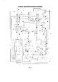
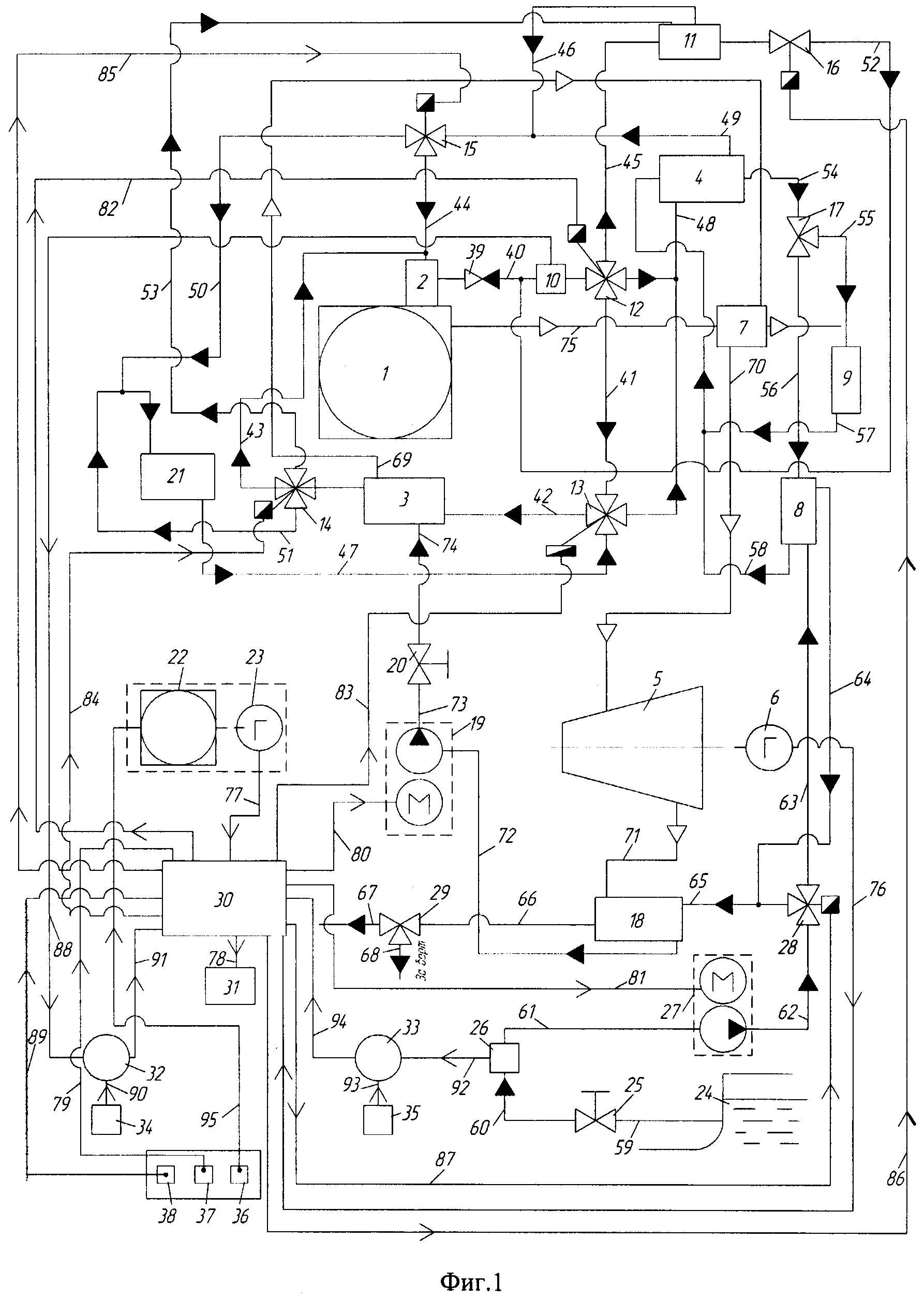
На фиг. 1 представлена схема судовой энергетической установки (СЭУ), которая содержит: главный судовой дизель 1; утилизационный котел (УК) 2; испаритель 3; абсорбционную холодильную машину (АБХМ) 4; турбину 5; генератор 6; пароперегреватель 7; холодильник 8; потребитель холода 9; датчики температуры (ДТ) 10, 26; теплоизолированную накопительную емкость (THE) 11; электронные четырехходовые краны 12, 13, 14; электронные трехходовые краны 15, 28; электромагнитный клапан (ЭМК) 16; трехходовые краны 17, 29; конденсатор 18; электрические насосы 19, 27; дроссель 20; главный судовой котел (ГСК) 21, дизель-генератор (поз. 22, 23); клинкет 24; вентиль 25; блок управления (БУ) 30; распределитель электроэнергии (главный распределительный щит) 31; блок сравнения (БС) 32, 33; задатчики 34, 35; 36 - переключатель режима СЭУ от дизель-генератора (поз. 22, 23), 37 - переключатель режима СЭУ от главного судового дизеля 1, 38 - переключатель режима СЭУ от ГСК 21; невозвратный клапан 39; каналы теплоносителей 40, 41, 42, 43, 44, 45, 46, 47, 48, 49, 50, 51, 52, 53; каналы хладоносителя 54, 55, 56, 57, 58; каналы забортной воды 59, 60, 61, 62, 63, 64, 65, 66, 67, 68; каналы низкокипящего вещества 69, 70, 71, 72, 73, 74; канал отработавших газов (ОГ) 75; каналы подачи выработанной электроэнергии 76, 77, 78; каналы подачи электроэнергии элементам установки 79, 80, 81, 82, 83, 84, 85, 86, 87, 95; каналы подачи электрических сигналов 88, 89, 90, 91, 92, 93, 94.In FIG. 1 is a diagram of a marine power plant (SEU), which contains: the main
Электронные трехходовые краны (ЭТК) 15, 28 выполняются согласно патенту №22709223 [3], а электронные четырехходовые краны (ЭЧК) 12, 13, 14 - по патенту №2253024 [4].Electronic three-way valves (ETC) 15, 28 are made according to patent No. 22709223 [3], and electronic four-way valves (ECH) 12, 13, 14 according to patent No. 2253024 [4].
Теплоноситель с температурой 95-98°С для испарения низкокипящего вещества циркулирует по замкнутым контурам, которые в зависимости от режимов работы судовой дизельной установки и его температуры поступает из УК 2, THE 11 и ГСК 21.The coolant with a temperature of 95-98 ° C for the evaporation of low-boiling matter circulates in closed circuits, which, depending on the operating modes of the ship's diesel engine and its temperature, come from UK 2, THE 11 and GSK 21.
При длительной остановке главного судового дизеля 1 в осенне-зимнее время работает ГСК 21 и соответственно предлагаемая СЭУ работает от ГСК 21.With a long stop of the main
В летнее время, когда ГСК 21 не работает, электроэнергию вырабатывает дизель-генератор (поз. 22, 23).In the summer, when GSK 21 is not working, a diesel generator generates electricity (
При нерабочем состоянии главного судового дизеля 1 АБХМ 4 работает от ГСК 21. Циркуляционный насос расположен в ГСК 21.When the main
Заявляемая судовая энергосберегающая установка работает следующим образом.The inventive ship energy-saving installation operates as follows.
1. Пусть судно эксплуатируется в летнее время, стоит на якоре, или у причала, соответственно ГСК 21 находится в нерабочем состоянии, судовую электроэнергию вырабатывает дизель-генератор (поз. 22, 23). Тз.в≥8°С. При этом переключатель режима 36 находится в подключенном состоянии, электроэнергия, полученная в дизель-генераторе (поз. 22, 23) по каналу 77 поступает в блок управления 30, который по каналу 78 подает электроэнергию в распределитель электроэнергии 31 и все судовые электропотребители находятся в подключенном состоянии, а СЭУ находится в нерабочем состоянии.1. Let the vessel operate in the summer, anchor, or at the berth, respectively GSK 21 is inoperative, the ship's electricity is generated by a diesel generator (pos. 22, 23). T zv ≥8 ° C. In this case, the
2. Пусть главный судовой дизель 1 приводится в действие - запускается. После пуска главного судового дизеля 1 начинает работать заявляемая энергосберегающая установка, в том числе утилизационный котел 2, при этом открывается вентиль 25. При достижении температуры теплоносителя утилизационного котла 2, например Тт≥85°С происходит переключение режима 36 на режим 37 и предлагаемая СЭУ начинает работать. При этом датчик температуры 10 подает сигнал по каналу 88 в БС 32, куда одновременно по каналу 90 поступает сигнал от задатчика 34, а обработанный сигнал по каналу 91 подается в БУ 30, который подает электроэнергию по каналам 80, 81, 82, 83, 84, 85, 86 и начинают работать электрические насосы 19, 27 и ЭЧК 12, 13, 14 и ЭТК 15, 28 и ЭМК 16. При этом ЭЧК 12 открывает каналы 40, 41, 45; ЭЧК 13 закрывает каналы 48, 47; ЭЧК 14 закрывает каналы 51, 53; ЭТК 15 закрывает канал 50; ЭТК 28 закрывает патрубок канала 65, если Тз.в≥8°С: открывает каналы 62, 63.2. Let the main
В УК 2 происходит нагрев теплоносителя до определенной температуры, например, до 95-98°С, и его передача через канал 40, ЭЧК 12, канал 41, ЭЧК 13, канал 42, испаритель 3, канал 43 и его возвращение по каналу 44 в УК 2, при этом его температура контролируется ДТ 10, циркуляционный насос контура на фиг. 1 не показан, который расположен в УК 2.In UK 2, the coolant is heated to a certain temperature, for example, to 95-98 ° C, and its transmission through
Другая часть теплоносителя от УК 2 через ЭЧК 12 по каналу 45 поступает в THE 11 и после теплообмена по каналам 46, 49, ЭТК 15, канал 44 возвращается в УК 2, а по каналам 40, 48 поступает в АБХМ 4 и отработанный теплоноситель по каналу 49, ЭТК 15, канал 44 возвращается в УК 2.The other part of the coolant from UK 2 through ECHK 12 through
В теплоизолированной накопительной емкости 11 во время работы главного судового дизеля 1 поддерживается 95-98°С.In the insulated
Забортная вода из клинкета 24 по каналу 59 через вентиль 25 и ДТ 26, канал 61 поступает в циркуляционный насос 27, а затем по каналу 62 поступает в ЭТК 28. При этом, если Тз.в≥8°С в БС 33 происходит обработка сигналов, поступающих от ДТ 26 и задатчика 35. Сигнал рассогласования в БС 33 по каналу 94 поступает в БУ 30, который подает электроэнергию по каналу 87 в ЭТК 28, который закрывает патрубок канала 65, открывает канал 63 и забортная вода по каналу 63 поступает в холодильник 8, куда одновременно по каналу 56 поступает хладоноситель от АБХМ 4, где в результате теплообмена забортная вода охлаждается до заданного значения Тз.в≤8°С и охлажденная забортная вода по каналам 64, 65 поступает в конденсатор 18. Циркуляционный насос хладоносителя не показан, он находиться в АБХМ 4. Одновременно в конденсатор 18 по каналу 71 поступает отработанный пар низкокипящего вещества из турбины 5. При этом забортная вода в результате теплообмена в конденсаторе 18 отбирает теплоту от отработанного пара, который превращается в жидкость, а забортная вода по каналу 66 поступает в трехходовой кран 29, который по каналу 67 направляет к судовым потребителям, например на камбуз и т.п., а другая часть по каналу 68 сливается за борт.Klinketa of
АБХМ 4 во время работы главного судового дизеля 1 работает от теплоносителя УК 2 согласно патенту №2466289 [5], теплоноситель циркулирует по замкнутому контуру, при этом теплоноситель от УК 2 через канал 40, ЭЧК 12, канал 48 поступает в АБХМ 4. Отработанный теплоноситель через канал 49, ЭТК 15, канал 44 возвращается в УК 2.ABHM 4 during operation of the main
Низкокипящее рабочее вещество (НРВ), как уже было отмечено выше, в результате теплообмена забортной водой с температурой Тз.в≤8°С, в конденсаторе 18 превращается в жидкость, которая по каналу 72 поступает в циркуляционный насос 19, который повышает давление низкокипящего вещества. Далее по каналу 73 проходит дроссель 20, где начинается кипение и парообразование и в полужидком состоянии по каналу 74 поступает в испаритель 3. Одновременно в испаритель 3 поступает по каналу 42 теплоноситель с температурой Тт≥95°С, при этом в результате теплообмена НРВ испаряется. Таким образом, обеспечивается разница температур испарения и конденсации НРВ, что позволяет преобразовать тепловую энергию ОГ с КПД более 10%. Выходя из испарителя 3 полученный пар НРВ проходит канал 69, пароперегреватель 7, установленный на канале 75 отработавших газов, где увеличивается его температура и давление, а далее по каналу 70 поступает в турбину 5 и совершает работу, вал которой связан с генератором 6. Выработанная электроэнергия по каналу 76 поступает в БУ 30, а затем по каналу 78 в распределитель электроэнергии 31. А отработанный пар по каналу 71 поступает в конденсатор 18 и цикл повторяется.The low-boiling working substance (NRW), as noted above, as a result of heat exchange with overboard water with a temperature of T.sub.v ≤8 ° C, in the
При снижении температуры теплоносителя в УК 2 Тт≤85°С во время выполнения судном маневров: при подходе к причалам, перестановке барж под погрузку и выгрузку, кратковременных остановках и т.п.сигнал от ДТ 10 по каналу 88 поступает в БС 32, куда одновременно поступает сигнал по каналу 90 от задатчика 34. При этом сигнал рассогласования по каналу 91 поступает в БУ 30, который подает электроэнергию по каналу 82 на ЭЧК 12, закрывается канал 45; по каналу 86 подается электроэнергия на ЭМК 16 и открывается канал 52, а ЭЧК 14 закрывает каналы 43, 51, открывает канал 53. Контур теплоносителя циркулирует через THE 11, канал 52, ЭМК 16, канал 40, ЭЧК 12, канал 41, ЭЧК 13, испаритель 3, канал 43, ЭЧК 14, канал 53 и возвращается в THE 11. Циркуляционный насос не показан, находиться в THE 11.When the temperature of the coolant in the UK 2T t ≤85 ° C during the execution of the ship’s maneuvers: when approaching the berths, moving barges for loading and unloading, short stops, etc., the signal from
3. Судно эксплуатируется в осенне-зимнее время. Тз.в≤8°С, СЭУ переключается на режим 38, при этом сигнал от ДТ 26 по каналу 92 подается в БС 33, куда одновременно по каналу 93 подается сигнал от задатчика 35, при этом сигнал рассогласования по каналу 94 подается в БУ 30, который подачей по каналу 87 электроэнергии на ЭТК 28 закрывает канал 63, открывает канал 65 и забортная вода по каналу 65 поступает в конденсатор 18 и аналогично по вышеописанному алгоритму производится работа данной установки.3. The vessel is operated in the autumn-winter time. T cv ≤8 ° С, the control system switches to
4. Судно на длительное время становится на якорь, например в ожидании выгрузки. При этом в зависимости от времени года эксплуатации может быть выполнены два варианта.4. The vessel anchors for a long time, for example, while waiting for unloading. In this case, depending on the season of operation, two options can be performed.
1 вариант. Судно эксплуатируется в летнее время, ГСК 21 находиться в выключенном состоянии. В этом случае останавливается главный судовой дизель 1 и одновременно включается переключатель 36 и по каналу 95 подается электроэнергия на дизель-генератор (поз. 22, 23), который запускается. Начинается выработка электроэнергии, которая по каналу 77 подается в БУ 30, а затем по каналу 78 в 31 для питания судовых потребителей.1 option. The vessel is operated in the summer,
2 вариант. Судно эксплуатируется в осенне-зимнее время, ГСК 21 находится в рабочем состоянии. При этом заявляемая СЭУ после остановки дизеля 1 будет находиться в рабочем состоянии и соответственно БУ 30 подачей электроэнергии на ЧХК 12, 13, 14 приводится в рабочее состояние и теплоноситель от ГСК 21 поступает в СЭУ. ЧХК 14 закрывает каналы 53, 43 открывает канал 51; ЭЧК 12 закрывает каналы 40, 41, 45; ЭЧК 13 закрывает канал 41. Тогда теплоноситель из ГСК 21 через канал 47, ЭЧК 13, канал 42, испаритель 3, канал 43, ЭЧК 14, канал 51 возвращается в ГСК 21. Одновременно теплоноситель по каналу 48 поступает в АБХМ 4, через канал 49, ЭТК 15 и каналы 50, 51 возвращается в ГСК 21. Циркуляционный насос находится в ГСК 21. Далее предлагаемая энергосберегающая установка работает по вышеуказанному алгоритму.
Таким образом, предлагаемая судовая энергосберегающая установка рейдовых и портовых судов, работающих постоянно на переменных нагрузках утилизируя тепловую энергию отработавших газов главного судового дизеля и главного судового котла позволяет выработать электроэнергию и обеспечить требуемой электроэнергией без использования дизель-генератора и валогенератора, что позволит увеличить топливную экономичность и коэффициент полезного действия судовой энергетической установки.Thus, the proposed ship energy-saving installation of raid and port vessels operating constantly under varying loads utilizing the thermal energy of the exhaust gases of the main marine diesel engine and the main marine boiler allows generating electricity and providing the required electricity without using a diesel generator and shaft generator, which will increase fuel economy and the efficiency of a ship power plant.
Источники информацииInformation sources
1. Патент №96550. Россия, МПК В63Н 23/24, F24J 2/00. Судовая электроэнергетическая установка / В.Н. Тимофеев, Д.В. Тимофеев. Опубл. 10.08.2010 в БИ №22.1. Patent No. 96550. Russia,
2. Патент №2184873. Россия, МПК F03G 6/00. Силовая установка на солнечной энергии / А.Ф. Исачкин. Опубл. в БИ 10.07.2002.2. Patent No. 2184873. Russia,
3. Патент №22709223. Россия, МПК F01P 7/16. Электрический термостат / В.Н. Тимофеев, Н.П. Кузин, А.Н. Краснов. Опубл. 27.02.06. Бюл. №6.3. Patent No. 22709223. Russia,
4. Патент №2253024. Россия, МПК F01P 7/14, 3/20. Устройство для регулирования рабочей температуры охлаждающей жидкости двигателя внутреннего сгорания / В.Н. Тимофеев, A.M. Поздеев, Л.В. Тимакова. Опубл. в БИ №15 27.05.2005.4. Patent No. 2253024. Russia,
5. Патент №2466289. Россия, МПК F02G 005/02, F02B 029/04, F02M 025/07. Система для охлаждения свежего заряда и отработавших газов судового дизеля, подаваемых на впуск / В.Н. Тимофеев, О.К. Безюков, О.В. Клюс, И.Г. Васильева, Д.В. Тимофеев. Опубл. 10.11.2012.5. Patent No. 2466289. Russia, IPC F02G 005/02, F02B 029/04, F02M 025/07. System for cooling the fresh charge and exhaust gases of a marine diesel engine supplied to the inlet / V.N. Timofeev, O.K. Bezyukov, O.V. Klyus, I.G. Vasiliev, D.V. Timofeev. Publ. 11/10/2012.
Claims (2)
Priority Applications (1)
| Application Number | Priority Date | Filing Date | Title |
|---|---|---|---|
| RU2016119864/11U RU166326U1 (en) | 2016-05-23 | 2016-05-23 | SHIP'S ENERGY SAVING INSTALLATION |
Applications Claiming Priority (1)
| Application Number | Priority Date | Filing Date | Title |
|---|---|---|---|
| RU2016119864/11U RU166326U1 (en) | 2016-05-23 | 2016-05-23 | SHIP'S ENERGY SAVING INSTALLATION |
Publications (1)
| Publication Number | Publication Date |
|---|---|
| RU166326U1 true RU166326U1 (en) | 2016-11-20 |
Family
ID=57792664
Family Applications (1)
| Application Number | Title | Priority Date | Filing Date |
|---|---|---|---|
| RU2016119864/11U RU166326U1 (en) | 2016-05-23 | 2016-05-23 | SHIP'S ENERGY SAVING INSTALLATION |
Country Status (1)
| Country | Link |
|---|---|
| RU (1) | RU166326U1 (en) |
Cited By (2)
| Publication number | Priority date | Publication date | Assignee | Title |
|---|---|---|---|---|
| RU176333U1 (en) * | 2016-12-07 | 2018-01-17 | Виталий Никифорович Тимофеев | Energy-saving installation of a riverboat |
| RU217073U1 (en) * | 2022-06-24 | 2023-03-16 | Федеральное государственное бюджетное образовательное учреждение высшего образования "Волжский государственный университет водного транспорта" | DEVICE FOR CONVERSING THERMAL ENERGY OF THE COOLING SYSTEM OF THE MAIN SHIP DIESEL INTO ELECTRIC ENERGY |
-
2016
- 2016-05-23 RU RU2016119864/11U patent/RU166326U1/en not_active IP Right Cessation
Cited By (3)
| Publication number | Priority date | Publication date | Assignee | Title |
|---|---|---|---|---|
| RU176333U1 (en) * | 2016-12-07 | 2018-01-17 | Виталий Никифорович Тимофеев | Energy-saving installation of a riverboat |
| RU217073U1 (en) * | 2022-06-24 | 2023-03-16 | Федеральное государственное бюджетное образовательное учреждение высшего образования "Волжский государственный университет водного транспорта" | DEVICE FOR CONVERSING THERMAL ENERGY OF THE COOLING SYSTEM OF THE MAIN SHIP DIESEL INTO ELECTRIC ENERGY |
| RU2805213C1 (en) * | 2022-11-14 | 2023-10-12 | Виталий Никифорович Тимофеев | Energy-saving device of ship's power plant on river vessel |
Similar Documents
| Publication | Publication Date | Title |
|---|---|---|
| Liang et al. | Analysis of an electricity–cooling cogeneration system based on RC–ARS combined cycle aboard ship | |
| Kyriakidis et al. | Modeling and optimization of integrated exhaust gas recirculation and multi-stage waste heat recovery in marine engines | |
| Mrzljak et al. | Change in steam generators main and auxiliary energy flow streams during the load increase of LNG carrier steam propulsion system | |
| KR20130026495A (en) | Marine denitration system, marine vessel equipped with same, and control method for marine denitration system | |
| WO2010116230A2 (en) | Deep ocean energy system with full or partial sea water air conditioning and utility waste heat utilization | |
| EP2762802A2 (en) | Chilled water system, ship, and method of operating chilled water system | |
| RU166326U1 (en) | SHIP'S ENERGY SAVING INSTALLATION | |
| CN203824151U (en) | LNG (liquefied natural gas) cold energy utilization device of LNG power driving vessel | |
| CN204555150U (en) | A kind of LNG Power Vessel air conditioner refrigerating/heating system | |
| CN111605667A (en) | A multi-energy complementary ship cold and hot water system | |
| Baldi et al. | The application of process integration to the optimisation of cruise ship energy systems: a case study | |
| KR101878825B1 (en) | Fresh water generating equipment for vessels by using waste heat | |
| de la Fuente et al. | Using the forward movement of a container ship navigating in the Arctic to air-cool a marine organic Rankine cycle unit | |
| CN110845065A (en) | Novel sea water desalination system based on marine engine | |
| Trzebiński | Technical aspects of using the heat pump at the ship | |
| RU217073U1 (en) | DEVICE FOR CONVERSING THERMAL ENERGY OF THE COOLING SYSTEM OF THE MAIN SHIP DIESEL INTO ELECTRIC ENERGY | |
| RU214374U1 (en) | DEVICE FOR AUTOMATIC TEMPERATURE CONTROL OF COOLANT LIQUID OF COOLING SYSTEM OF MARINE INTERNAL COMBUSTION ENGINE | |
| RU187571U1 (en) | SYSTEM OF REGULATING THE TEMPERATURE OF THE AIRBURNING AIR OF THE MARINE INTERNAL COMBUSTION ENGINE | |
| RU223859U1 (en) | Device for direct conversion of thermal energy of exhaust gases into electrical energy of marine diesel engines | |
| RU2805213C1 (en) | Energy-saving device of ship's power plant on river vessel | |
| RU167801U1 (en) | System for automatic regulation of the thermal regime of a marine internal combustion engine | |
| RU2652362C1 (en) | Houseboat | |
| KR20110063935A (en) | Energy-saving vessel equipped with generator using temperature difference | |
| RU176333U1 (en) | Energy-saving installation of a riverboat | |
| RU2805458C1 (en) | Nuclear power unit for nuclear-powered ships |
Legal Events
| Date | Code | Title | Description |
|---|---|---|---|
| MM9K | Utility model has become invalid (non-payment of fees) |
Effective date: 20170524 |