Полезная модель относится к области машиностроения и ремонтного производства и может быть использована для сборки узлов, например, для запрессовки гильзы в блок цилиндров двигателя при восстановлении блока методом запрессовки «сухих» гильз или при замене «мокрых» гильз.The utility model relates to the field of mechanical engineering and repair production and can be used to assemble assemblies, for example, to press the liner into the engine block when restoring the block by pressing the "dry" liner or replacing the "wet" liner.
Известны гидравлические прессы [http://www.vseinstrumenti.ru], в широком ассортименте выпускаемые промышленностью. Недостатками их применения при запрессовке гильз в блок цилиндров двигателя являются: во-первых - сложность базирования и закрепления блока на прессе (особенно V-образного); во-вторых - дороговизна и большие габаритные размеры пресса. Указанные недостатки обуславливают нецелесообразность использования гидравлических прессов при запрессовке гильз в блок цилиндров двигателя и необходимость применения специальных приспособлений, аналогом которых является приспособление [http://zil131.net/zil/980], в котором усилие запрессовки передается от рукоятки через винтовую передачу с использованием нижнего упора в виде диска или тарелки. Недостатком конструкции приспособления является необходимость кантования (поворачивания) блока цилиндров при установке упора и штока со сменой установа (закрепления), так как перед запрессовкой «сухой» гильзы цилиндры растачиваются, и блок при этом закреплен на столе расточного станка. После крепления приспособления перед запрессовкой гильзы, а также для удаления приспособления после запрессовки перед растачиванием «сухой» гильзы под поршень, опять возникает необходимость в кантовании и креплении самого блока.Known hydraulic presses [http://www.vseinstrumenti.ru], in a wide range produced by the industry. The disadvantages of their use when pressing liners into the engine block are: firstly, the difficulty of basing and securing the block on a press (especially a V-shaped one); secondly - the high cost and large overall dimensions of the press. These shortcomings cause the inappropriateness of using hydraulic presses when pressing liners into the engine block of the engine and the need to use special devices, the analogue of which is the device [http://zil131.net/zil/980], in which the pressing force is transmitted from the handle through a screw drive using bottom stop in the form of a disk or plate. The disadvantage of the design of the device is the need for tipping (turning) the cylinder block when installing the stop and the rod with a change in the installation (fixing), because before pressing the "dry" liner the cylinders are bored, and the block is mounted on the table of the boring machine. After attaching the device before pressing the sleeve, and also to remove the device after pressing before boring the "dry" sleeve under the piston, again there is a need for tipping and fixing the block itself.
Также известно приспособление [http://darlomt.ru/sborka-bloka-cilindrov-dvigatelya-d50-chast-1/], которое частично устраняет недостатки аналога и принято за прототип. В отличие от аналога у прототипа отсутствует нижний упор, а его функцию выполняет траверса, которая устанавливается на шпильках крепления головки блока цилиндров, что устраняет необходимость кантования блока после растачивания цилиндров перед запрессовкой гильз. Недостатком конструкции прототипа является то, что длина запрессовки гильзы ограничена длиной шпилек. Данное ограничение не оказывает влияния на процесс запрессовки «мокрых» гильз, так как длина их запрессовки равна длине посадочных поясков гильзы и значительно меньше длины шпилек. Но, что касается установки «сухих» гильз, то их запрессовка осуществляется на всю длину, которая больше, чем длина шпилек крепления ГБЦ. При этом возникает необходимость в изготовлении специальных длинных шпилек, причем с учетом того, что размеры резьбовых отверстий в блоках цилиндров различных моделей двигателей отличаются.Also known device [http://darlomt.ru/sborka-bloka-cilindrov-dvigatelya-d50-chast-1/], which partially eliminates the disadvantages of the analogue and is taken as a prototype. In contrast to the analogue, the prototype does not have a lower stop, and its function is performed by a traverse, which is installed on the studs for fastening the cylinder head, which eliminates the need for tilting the block after boring the cylinders before pressing the liners. The disadvantage of the design of the prototype is that the length of the press-in sleeve is limited by the length of the studs. This restriction does not affect the process of pressing wet sleeves, since the length of their pressing is equal to the length of the landing belts of the sleeve and much less than the length of the studs. But, with regard to the installation of "dry" sleeves, then they are pressed into the entire length, which is greater than the length of the cylinder head mounting studs. This necessitates the manufacture of special long studs, taking into account the fact that the sizes of the threaded holes in the cylinder blocks of different engine models are different.
Технической задачей данной полезной модели является обеспечение возможности запрессовки в блок цилиндров гильз различной длины без кантования блока после растачивания под гильзу перед запрессовкой и после запрессовки перед растачиванием под поршень.The technical task of this utility model is to provide the possibility of pressing liners of various lengths into the cylinder block without tilting the block after boring under the liner before pressing and after pressing before boring under the piston.
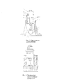
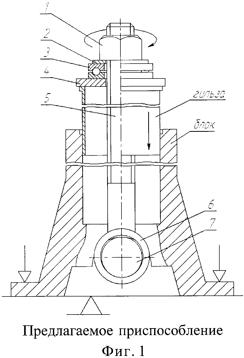
Поставленная задача решается с помощью приспособления (фиг. 1 и фиг. 2) состоящего из винта 5, к которому в нижней части прикреплено кольцо 6 разъемным или неразъемным соединением, например, сваркой. В кольцо свободно вставлен валик 7, длина которого больше расстояния между соседними постелями блока цилиндров для коренных подшипников коленчатого вала двигателя и перекрывает их. Также в комплект приспособления входят: верхний упор 4 в виде диска, диаметр которого больше наружного диаметра запрессовываемой гильзы; упорный подшипник 3; шайба 2 и гайка 7, накручиваемая на винт для создания усилия запрессовки на гильзу через подшипник и верхний упор с учетом упора валика в поверхность постелей блока через кольцо. Наличие кольца в конструкции приспособления позволяет применять валик в качестве нижнего упора, причем имеется возможность вставки валика в кольцо и удаления из кольца перемещением под постелями блока без кантования блока и смены установа после растачивания цилиндров под гильзу перед запрессовкой и после запрессовки перед растачиванием под поршень. Возможность изготовления винта с резьбой требуемой длины позволяет запрессовывать как короткие, так и длинные гильзы. Таким образом, предлагаемое приспособление является универсальным устройством для запрессовки гильз различной длины в блок цилиндров двигателя без смены установа и кантования блока, что не только уменьшает технологическое время на восстановление блока, но и снижает риск производственного травматизма при кантовании.The problem is solved using the device (Fig. 1 and Fig. 2) consisting of a screw 5, to which in the lower part is attached a ring 6 with a detachable or one-piece connection, for example, by welding. A roller 7 is freely inserted in the ring, the length of which is greater than the distance between adjacent beds of the cylinder block for the main bearings of the engine crankshaft and overlaps them. Also included in the device kit: top stop 4 in the form of a disk, the diameter of which is larger than the outer diameter of the pressed sleeve; thrust bearing 3; a washer 2 and a nut 7 screwed onto a screw to create a pressing force on the sleeve through the bearing and the upper stop, taking into account the emphasis of the roller on the surface of the unit’s bed through the ring. The presence of the ring in the design of the device allows the roller to be used as a lower stop, and it is possible to insert the roller into the ring and remove it from the ring by moving under the bed of the block without tilting the block and changing the setting after boring the cylinders under the sleeve before pressing in and after pressing in before boring under the piston. The possibility of manufacturing a screw with a thread of the required length allows you to press in both short and long sleeves. Thus, the proposed device is a universal device for pressing liners of various lengths into the engine block without changing the installation and tilting of the block, which not only reduces the technological time for restoration of the block, but also reduces the risk of industrial injuries during tilting.