RU134547U1 - MASSIVE FOUNDATION FOR VIBRATION EQUIPMENT - Google Patents
MASSIVE FOUNDATION FOR VIBRATION EQUIPMENT Download PDFInfo
- Publication number
- RU134547U1 RU134547U1 RU2013127004/03U RU2013127004U RU134547U1 RU 134547 U1 RU134547 U1 RU 134547U1 RU 2013127004/03 U RU2013127004/03 U RU 2013127004/03U RU 2013127004 U RU2013127004 U RU 2013127004U RU 134547 U1 RU134547 U1 RU 134547U1
- Authority
- RU
- Russia
- Prior art keywords
- foundation
- vibration
- duct
- equipment
- massive
- Prior art date
Links
Images
Landscapes
- Buildings Adapted To Withstand Abnormal External Influences (AREA)
- Foundations (AREA)
Abstract
1. Массивный фундамент под вибрационное оборудование, содержащий жесткий монолитный короб, фундаментный блок, предназначенный для установки на нем вибрационного оборудования и размещенный в коробе с зазором относительно стенок и днища короба, виброизоляторы, установленные на днище короба, на которые опирается фундаментный блок, отличающийся тем, что он дополнительно содержит подшаботную прокладку для вибрационного оборудования, а фундаментный блок состоит из двух слоев, нижний из которых выполнен из железобетона, а верхний слой - из стале-фиброжелезобетона высотой, равной например 1/3 высоты фундаментного блока, при этом в центральной части верхнего слоя выполнена выемка для установки в ней через подшаботную прокладку вибрационного оборудования.2. Массивный фундамент под вибрационное оборудование по п.1, отличающийся тем, что в центральной части короба выполнен приямок, и в нем установлена дополнительная опора для фундаментного блока, на которую он опирается через виброизолятор.3. Массивный фундамент под вибрационное оборудование по п.1, отличающийся тем, что подшаботная прокладка под вибрационное оборудование выполнена из дубовых брусьев, собранных в один или несколько щитов толщиной не менее 100 мм.1. A massive foundation for vibration equipment containing a rigid monolithic duct, a foundation block designed for installation of vibration equipment on it and placed in a duct with a gap relative to the walls and bottom of the duct, vibration isolators installed on the bottom of the duct, on which the foundation block rests, characterized in that it additionally contains a sub-base gasket for vibration equipment, and the foundation block consists of two layers, the lower of which is made of reinforced concrete, and the upper layer is made of steel les fibrozhelezobetona height equal to 1/3 of the height of the foundation such as block, the central portion of the upper layer has a recess for mounting therein through podshabotnuyu gasket oborudovaniya.2 vibration. The massive foundation for vibration equipment according to claim 1, characterized in that a pit is made in the central part of the duct, and an additional support for the foundation block is installed in it, on which it is supported through a vibration isolator. 3. The massive foundation for vibrating equipment according to claim 1, characterized in that the underwork pad for vibrating equipment is made of oak beams assembled into one or more panels of at least 100 mm thickness.
Description
Полезная модель относится к несущим строительным конструкциям промышленных зданий, а именно к массивным фундаментам, используемым под установку оборудования с повышенным режимом работы и испытывающим динамические воздействия.The utility model relates to load-bearing building structures of industrial buildings, namely to massive foundations used for installation of equipment with increased operating conditions and experiencing dynamic effects.
Известна регулируемая опора для вибрационных устройств по патенту РФ на изобретение №2082036. Опора содержит: нижнее основание и верхнее основание, упругие пластины с центральным отверстием, выполненные, например, из резины, ограничительные стержни, пропущенные в отверстия продольных бортов нижнего основания, которое выполнено в виде металлического короба, содержит плиту с отверстиями под фундаментные болты, продольные борта и поперечные борта. Ограничительные стержни закреплены с двух концов гайками. Упругие прямоугольные пластины, имеющие двусторонние фаски по контуру, размещены между продольными и поперечными бортами без зазора и вплотную к ним своими торцевыми поверхностями. Верхнее основание состоит из опорной плиты, усиленной ребрами, приваренными к вертикальному штырю и опорному кольцу, на котором размещено упругое кольцо из полимерного материала. Нижний конец штыря без зазора помещен в центральные отверстия упругих пластин. Между нижним концом штыря и плитой имеется зазор, обеспечивающий возможность вертикальных упругих перемещений верхнего основания относительно нижнего основания опоры. Сверху штыря жестко закреплен направляющий конусный наконечник, на который своим посадочным отверстием помещен колеблющийся объект.Known adjustable support for vibration devices according to the patent of the Russian Federation for the invention No. 2082036. The support comprises: a lower base and an upper base, elastic plates with a central hole made of, for example, rubber, restrictive rods passed into the holes of the longitudinal sides of the lower base, which is made in the form of a metal box, contains a plate with holes for foundation bolts, longitudinal sides and transverse sides. The restriction rods are fixed at both ends with nuts. Elastic rectangular plates having two-sided chamfers along the contour are placed between the longitudinal and transverse sides without a gap and close to them with their end surfaces. The upper base consists of a base plate reinforced with ribs welded to a vertical pin and a support ring on which an elastic ring of polymer material is placed. The lower end of the pin without a gap is placed in the central holes of the elastic plates. Between the lower end of the pin and the plate there is a gap that allows vertical elastic movement of the upper base relative to the lower base of the support. A guide cone tip is rigidly fixed on top of the pin, onto which an oscillating object is placed with its landing hole.
Данная опора для вибрационных устройств позволяет создавать виброустановки с колеблющимся объектом практически любой большой массы и габаритов, упрощает их конструкцию, уменьшает расход материалов, улучшает условия монтажа и изменения жесткости опор, однако данная опора не может использоваться под оборудование с повышенными режимами работы. В частности не обеспечивается повышенная повышенная несущая способность фундамента при действии многократно повторяющейся нагрузки.This support for vibration devices allows you to create vibration systems with an oscillating object of almost any large mass and dimensions, simplifies their design, reduces material consumption, improves installation conditions and changes in the stiffness of the supports, but this support cannot be used for equipment with increased operating conditions. In particular, the increased increased bearing capacity of the foundation under the action of repeatedly repeated loads is not provided.
Известны виброизолированные фундаменты, которые используются в строительстве для машин и оборудования с динамическими нагрузками (патенты на изобретение №2281998, 2282001, 2283398). Эти фундаменты содержат ванну, фундаментный блок, размещенный в ванне с зазором относительно ее днища и стенок, и виброизоляторы, которые связаны с фундаментным блоком. Все указанные фундаменты различаются конструктивным выполнением виброизоляторов.Known vibration-proof foundations that are used in construction for machinery and equipment with dynamic loads (invention patents No. 2281998, 2282001, 2283398). These foundations contain a bath, a foundation block placed in the bath with a gap relative to its bottom and walls, and vibration isolators, which are connected to the foundation block. All of these foundations differ in the design of vibration isolators.
В качестве недостатков каждой из представленных конструкций виброизолированных фундаментов можно отметить низкую прочность бетона верхней части фундаментного блока, на которую непосредственно передается вибрационное воздействие.As the disadvantages of each of the designs of vibration-insulated foundations, it is possible to note the low concrete strength of the upper part of the foundation block, to which the vibration effect is directly transmitted.
За прототип принят виброизоляционный фундамент по авторскому свидетельству СССР №1434037, МПК E02D 27/44, который содержит ванну (короб) и фундаментный блок, который размещен в ванне с зазором относительно ее стенок и днища и опирается на виброизоляторы, установленные на днище ванны. Виброизоляторы выполнены в виде Катковых опор, связанных между собой пружинами, и наклонных стержней, шарнирно смонтированных на Катковых опорах. В днище фундаментного блока выполнены радиусные выемки с опорными поверхностями, образующие которых перпендикулярны направлению перемещения Катковых опор. Выемки ограничены в нижней части упорами. Каждый наклонный стержень своим свободным концом размещен в соответствующей радиусной выемке, контактирует с ее опорной поверхностью и подпружинен в направлении уменьшения угла его наклона относительно вертикали. Конструкция по прототипу обладает повышенными защитными свойствами к виброударным нагрузкам, что приводит к повышению эффективности виброизоляции фундамента.The vibration isolation foundation according to the USSR author's certificate No. 1434037, IPC E02D 27/44, which contains a bathtub (box) and a foundation block, which is placed in the bathtub with a gap relative to its walls and bottom and rests on vibration isolators installed on the bottom of the bathtub, is adopted as a prototype. Vibration isolators are made in the form of roller bearings, interconnected by springs, and inclined rods pivotally mounted on the roller bearings. Radial recesses with supporting surfaces are made at the bottom of the foundation block, the generatrices of which are perpendicular to the direction of movement of the roller bearings. The recesses are limited at the bottom by stops. Each inclined rod with its free end is placed in a corresponding radius recess, is in contact with its supporting surface and spring-loaded in the direction of decreasing the angle of inclination relative to the vertical. The design of the prototype has increased protective properties to shock loads, which leads to increased efficiency of vibration isolation of the foundation.
Данный виброизоляционный фундамент обладает повышенными защитными свойствами к виброударным нагрузкам благодаря наличию трех ступеней виброзащитного каскада, вследствие разной жесткости которых снижается собственная частота колебаний системы в вертикальном направлении, что улучшает виброизолирующие свойства фундамента при динамических нагрузках. Недостатком данного фундамента является низкая прочность бетона верхней части фундаментного блока, на которую непосредственно передается вибрационное воздействие. Низкая прочность фундаментного блока снижает долговечность и живучесть применяемого виброизоляционного фундамента.This vibration isolation foundation has increased protective properties against vibration shock due to the presence of three stages of the vibration protection cascade, due to the different stiffness of which the natural frequency of the system oscillations in the vertical direction is reduced, which improves the vibration insulation properties of the foundation under dynamic loads. The disadvantage of this foundation is the low concrete strength of the upper part of the foundation block, to which the vibration effect is directly transmitted. The low strength of the foundation block reduces the durability and survivability of the applied vibration isolation foundation.
Задача полезной модели - обеспечить повышенную прочность, долговечность и трещиностойкость железобетонного фундамента при действии многократно повторяющейся нагрузки (вибрации) при одновременном уменьшении материалоемкости. Технический результат, на достижение которого направлена решаемая задача, заключается в повышении сопротивления динамическим нагрузкам массивного железобетонного фундамента путем упрочнения, а также в снижении вибрационного воздействия на фундамент путем частичного гашения вибраций в подшаботной прокладке.The objective of the utility model is to provide increased strength, durability, and crack resistance of a reinforced concrete foundation under the action of repeatedly repeated loads (vibrations) while reducing material consumption. The technical result, the achievement of which the problem is aimed at, is to increase the resistance to dynamic loads of a massive reinforced concrete foundation by hardening, as well as to reduce the vibration effect on the foundation by partially damping vibrations in the underbody installation.
Задача решена следующим образом.The problem is solved as follows.
Заявляемый в качестве полезной модели массивный фундамент под вибрационное оборудование, как и прототип, содержит жесткий монолитный короб, фундаментный блок, предназначенный для установки на нем вибрационного оборудования и размещенный в коробе с зазором относительно стенок и днища короба, и виброизоляторы, установленные на днище короба, на которые опирается фундаментный блок.Declared as a utility model, the massive foundation for vibration equipment, like the prototype, contains a rigid monolithic duct, a foundation block designed for installation of vibration equipment on it and placed in the duct with a gap relative to the walls and bottom of the duct, and vibration isolators mounted on the bottom of the duct, on which the foundation block rests.
В отличие от прототипа массивный фундамент под вибрационное оборудование согласно полезной модели дополнительно содержит подшаботную прокладку для вибрационного оборудования, выполненную, например, из дубовых брусьев, собранных в один или несколько щитов толщиной не менее 100 мм. Фундаментный блок состоит из двух слоев, нижний из которых выполнен из железобетона, а верхний слой - из сталефиброжелезобетона. Отличием является и то, что в центральной части верхнего слоя фундаментного блока выполнена выемка для установки в ней через подшаботную прокладку вибрационного оборудования. Кроме того в центральной части короба выполнен приямок, и в нем установлена дополнительная опора для фундаментного блока, на которую он опирается через виброизолятор.In contrast to the prototype, the massive foundation for vibration equipment according to the utility model additionally contains a sub-base gasket for vibration equipment made, for example, of oak beams assembled in one or more panels of at least 100 mm thickness. The foundation block consists of two layers, the lower of which is made of reinforced concrete, and the upper layer is made of steel fiber reinforced concrete. The difference is that in the central part of the upper layer of the foundation block, a recess is made for installation in it through the underworking laying of vibration equipment. In addition, a pit is made in the central part of the box, and an additional support for the foundation block is installed in it, on which it is supported through a vibration isolator.
Наилучшим вариантом выполнения фундаментного блока является такой, когда высота его верхнего сталефиброжелезобетонного слоя составляет 1/3 высоты фундаментного блока.The best embodiment of the foundation block is when the height of its upper steel-fiber-reinforced concrete layer is 1/3 of the height of the foundation block.
Такие свойства сталефибробетона, как повышенные ударная прочность, вязкость, пластичность, высокая прочность при воздействии многократно действующей нагрузки позволяют применять его для армирования конструкций, подверженных интенсивным динамическим воздействиям, многократно повторяющимся и вибрационным нагрузкам. Наличие сталефиброжелезобетонного слоя позволяет повысить в 2-3 раза прочность, долговечность и живучесть массивного фундамента под вибрационное оборудование.Such properties of steel fiber reinforced concrete as increased impact strength, toughness, ductility, high strength when exposed to repeatedly acting loads allow it to be used to reinforce structures subject to intense dynamic stresses, repeatedly repeated and vibration loads. The presence of a steel-fiber-reinforced concrete layer allows to increase by 2-3 times the strength, durability and survivability of a massive foundation for vibration equipment.
Помимо этого, подшаботная прокладка частично гасит вибрации и препятствует распространению их на фундамент.In addition, the underwork gasket partially dampens the vibrations and prevents them from spreading to the foundation.
Следовательно, заявляемый массивный сталефиброжелезобетонный фундамент позволяет существенно повысить жизненный цикл фундаментов под вибрационное оборудование. А именно, увеличить межремонтный период основных строительных фондов производства. При этом, появляется возможность применения более современного и мощного оборудования на тех же площадях за счет увеличения несущей способности, долговечности и живучести фундаментов.Therefore, the claimed massive steel-fiber reinforced concrete foundation can significantly increase the life cycle of foundations for vibration equipment. Namely, to increase the overhaul period of the main construction funds of production. At the same time, it becomes possible to use more modern and powerful equipment in the same areas by increasing the bearing capacity, durability and survivability of the foundations.
Совокупность существенных признаков, характеризующих заявляемое устройство, в известных источниках информации не обнаружена, что подтверждает новизну полезной модели.The set of essential features characterizing the claimed device in the known sources of information is not found, which confirms the novelty of the utility model.
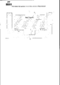
Полезная модель пояснена чертежом, на котором приведен общий вид массивного сталефиброжелезобетонного фундамента под вибрационное оборудование.The utility model is illustrated in the drawing, which shows a general view of a massive steel-fiber-reinforced concrete foundation for vibration equipment.
Конструкция фундамента 5 смонтирована на подфундаментный короб 1 и состоит из двух слоев по высоте: первый слой 7 - железобетонный, второй 6 - сталефиброжелезобетонный. Фундамент 5 опирается черз виброизоляторы 9 на подфундаментный короб 1 и в центре для уменьшения расчетного пролета опирается на фундаментную опору 8 под виброизолятор 9. В качестве виброизоляторов могут быть использованы любые упругие элементы, например, массивные металлические пружины или резиновые амортизаторы. Для уменьшения интенсивности вибрации, а следовательно, для уменьшения разрушительных воздействий на фундамент, между поверхностью фундамента 5 и оборудованием 4 делают подшаботную прокладку 3, состоящую из дубовых брусьев, собранных в один или несколько щитов. Толщину каждого щита принимают в зависимости от величины вибрации, но не менее 100 мм. Возможно и иное выполнение подшаботной прокладки согласно разработанному проекту.The construction of the foundation 5 is mounted on the foundation box 1 and consists of two layers in height: the first layer 7 is reinforced concrete, the second 6 is steel fiber reinforced concrete. The foundation 5 is supported by vibration isolators 9 on the basement box 1 and in the center, to reduce the calculated span, it is supported by the foundation support 8 under the vibration isolator 9. Any elastic elements, for example, massive metal springs or rubber shock absorbers, can be used as vibration isolators. To reduce the intensity of vibration, and therefore, to reduce the destructive effects on the foundation, between the surface of the foundation 5 and
На фундамент 5 в центре устанавливается вибрационное оборудование 4 через подшаботную прокладку 3. На жесткий монолитный подфундаментный короб 1 сверху укладывается бетонный пол 2.On the foundation 5 in the center,
Верхний сталефиброжелезобетонный слой 6 фундамента 5 примыкает к подшаботной прокладке 3. Армирование фундамента осуществляется согласно проектным нормативам.The upper steel-fiber-reinforced concrete layer 6 of the foundation 5 is adjacent to the under-
Устройство работает следующим образом.The device operates as follows.
При вибрационном воздействии оборудования 4 возбуждение через верхний сталефиброжелезобетонный слой 6 передается на нижний железобетонный слой 7 и гасится виброизоляторами 9. При этом интенсивность вибрационного воздействия практически полностью воспринимается верхним сталефиброжелезобетонным слоем 6, который является более эффективным при динамическом воздействии, чем железобетонный слой 7, в связи с чем не происходит разрушений нижнего слоя 6, т.к. деформационная волна практически погашается при достижении нижнего слоя. С помощью виброизоляторов 9 происходит гашение динамических вибрационных волн на весь фундамент и за счет них обеспечивается общая устойчивость.When the vibration effect of
Кроме того, за счет применения слоя из сталефиброжелезобетона требуется меньший расход арматуры у предлагаемого фундамента по сравнению с обычным железобетонным, материалоемкость фундамента получается ниже, чем у прототипа. Применение предлагаемого устройства позволяет повысить эффективность гашения колебаний и снизить материалоемкость системы вибрационной защиты.In addition, due to the use of a layer of steel fiber reinforced concrete, a lower consumption of reinforcement is required for the proposed foundation compared to conventional reinforced concrete, the material consumption of the foundation is lower than that of the prototype. The application of the proposed device can improve the damping of oscillations and reduce the material consumption of the vibration protection system.
Claims (3)

Priority Applications (1)
| Application Number | Priority Date | Filing Date | Title |
|---|---|---|---|
| RU2013127004/03U RU134547U1 (en) | 2013-06-13 | 2013-06-13 | MASSIVE FOUNDATION FOR VIBRATION EQUIPMENT |
Applications Claiming Priority (1)
| Application Number | Priority Date | Filing Date | Title |
|---|---|---|---|
| RU2013127004/03U RU134547U1 (en) | 2013-06-13 | 2013-06-13 | MASSIVE FOUNDATION FOR VIBRATION EQUIPMENT |
Publications (1)
| Publication Number | Publication Date |
|---|---|
| RU134547U1 true RU134547U1 (en) | 2013-11-20 |
Family
ID=49555410
Family Applications (1)
| Application Number | Title | Priority Date | Filing Date |
|---|---|---|---|
| RU2013127004/03U RU134547U1 (en) | 2013-06-13 | 2013-06-13 | MASSIVE FOUNDATION FOR VIBRATION EQUIPMENT |
Country Status (1)
| Country | Link |
|---|---|
| RU (1) | RU134547U1 (en) |
Cited By (3)
| Publication number | Priority date | Publication date | Assignee | Title |
|---|---|---|---|---|
| CN105887919A (en) * | 2016-04-25 | 2016-08-24 | 中建六局土木工程有限公司 | Mounting and constructing method of rotary hub equipment and high-tonnage foundation mass block |
| CN108425378A (en) * | 2018-04-08 | 2018-08-21 | 北京航天希尔测试技术有限公司 | A kind of large size air supporting vibration damping ground |
| CN109295997A (en) * | 2018-11-15 | 2019-02-01 | 中冶京诚工程技术有限公司 | A kind of Vibration-Isolated Foundation for Forging Hammers |
-
2013
- 2013-06-13 RU RU2013127004/03U patent/RU134547U1/en not_active IP Right Cessation
Cited By (5)
| Publication number | Priority date | Publication date | Assignee | Title |
|---|---|---|---|---|
| CN105887919A (en) * | 2016-04-25 | 2016-08-24 | 中建六局土木工程有限公司 | Mounting and constructing method of rotary hub equipment and high-tonnage foundation mass block |
| CN105887919B (en) * | 2016-04-25 | 2017-11-07 | 中建六局土木工程有限公司 | A kind of construction method of installation of rotating hub equipment and gross ton position mass of foundation block |
| CN108425378A (en) * | 2018-04-08 | 2018-08-21 | 北京航天希尔测试技术有限公司 | A kind of large size air supporting vibration damping ground |
| CN109295997A (en) * | 2018-11-15 | 2019-02-01 | 中冶京诚工程技术有限公司 | A kind of Vibration-Isolated Foundation for Forging Hammers |
| CN109295997B (en) * | 2018-11-15 | 2024-02-06 | 中冶京诚工程技术有限公司 | Forging hammer shock insulation foundation |
Similar Documents
| Publication | Publication Date | Title |
|---|---|---|
| KR100952232B1 (en) | Stable friction damper for lintel beam | |
| RU134547U1 (en) | MASSIVE FOUNDATION FOR VIBRATION EQUIPMENT | |
| Bhandari et al. | Dynamic analysis of machine foundation | |
| CN206591421U (en) | Adjustable rigidity particle damping shock absorber | |
| KR101301143B1 (en) | Seismic retrofit structure of pilotiies construction | |
| RU2641335C2 (en) | Kochetov's seismic-resistant building | |
| JP2020012280A (en) | Vibration isolation structure for rigid-frame viaduct | |
| JP3898509B2 (en) | Function change repair method for existing elastic bearings | |
| ATE419479T1 (en) | BEARING CONSTRUCTION FOR DAMPED TRANSMISSION OF SHOCK AND/OR VIBRATION FORCES | |
| CN111043454A (en) | Basic platform for vibration reduction and isolation of mechanical equipment and design method thereof | |
| RU2568192C1 (en) | Earthquake resistance building | |
| KR101341847B1 (en) | Seismic reinforce device structure for bridge and construction method | |
| KR20120035409A (en) | Anti vibration device for construction | |
| KR20080057517A (en) | Slab earthquake resistant construction | |
| RU101725U1 (en) | SEISMICALLY RECONSTRUCTED, RESTORED OR CONSTRUCTED BUILDING OR CONSTRUCTION | |
| CN104879437A (en) | Composite slipping energy-dissipating vibration-isolating method for vibration-isolating supporting base | |
| RU2658940C2 (en) | Earthquake-resistant low noise building | |
| CN106702886A (en) | Variable-rigidity particle damping shock absorption device suitable for bridge | |
| Fiebig | Reduction of vibrations of pedestrian bridges using tuned mass dampers (TMD) | |
| RU2641334C2 (en) | Kochetov's seismic-resistant building | |
| CN104652647B (en) | tuned mass damper | |
| CN105178184A (en) | Friction damper | |
| CN205639458U (en) | Shale shaker damping support | |
| RU2293160C2 (en) | Foundation for vertical steel tank to be built in seismic zone | |
| RU183267U1 (en) | FOUNDATION OF BUILDING, STRUCTURES OF SMALL RIGIDITY |
Legal Events
| Date | Code | Title | Description |
|---|---|---|---|
| MM1K | Utility model has become invalid (non-payment of fees) |
Effective date: 20140614 |