RU120092U1 - CATALYTIC SYNTHESIS GAS GENERATOR RADIAL TYPE - Google Patents
CATALYTIC SYNTHESIS GAS GENERATOR RADIAL TYPE Download PDFInfo
- Publication number
- RU120092U1 RU120092U1 RU2011141361/05U RU2011141361U RU120092U1 RU 120092 U1 RU120092 U1 RU 120092U1 RU 2011141361/05 U RU2011141361/05 U RU 2011141361/05U RU 2011141361 U RU2011141361 U RU 2011141361U RU 120092 U1 RU120092 U1 RU 120092U1
- Authority
- RU
- Russia
- Prior art keywords
- gas
- catalyst
- generator
- air
- synthesis gas
- Prior art date
Links
Abstract
1. Каталитический генератор синтез-газа радиального типа, содержащий смеситель и катализатор, отличающийся тем, что катализатор выполнен в виде цилиндрического газопроницаемого блока, генератор содержит распределитель потока газовой смеси и теплообменное устройство. ! 2. Устройство по п.1, отличающееся тем, что катализатор может быть выполнен в виде гранул, размещенных между внешней поверхностью меньшего по радиусу и внутренней поверхностью большего по радиусу цилиндров с перфорированными стенками. ! 3. Устройство по п.1, отличающееся тем, что содержит распределитель потока газовой смеси, размещенный внутри газопроницаемого цилиндрического катализатора, который представляет собой систему закрепленных на общей оси дисков разного диаметра, обеспечивающую выравнивание неоднородности газового потока через катализатор. ! 4. Устройство по п.1, отличающееся тем, что теплообмен между продуктами реакции и подающимися на катализатор газами может осуществляться в корпусе генератора или отдельно в вынесенном теплообменном устройстве. ! 5. Устройство по пп.1-4, отличающееся тем, что объемное соотношение воздух:углеводородный газ при запуске генератора составляет (8,0-10,0):1, в режиме генерации синтез-газа - объемное соотношение воздух:углеводородный газ составляет (2,5-4,0):1. 1. A radial-type catalytic synthesis gas generator containing a mixer and a catalyst, characterized in that the catalyst is made in the form of a cylindrical gas-permeable unit, the generator contains a gas mixture flow distributor and a heat exchanger. ! 2. The device according to claim 1, characterized in that the catalyst can be made in the form of granules located between the outer surface of a smaller radius and the inner surface of a larger radius of cylinders with perforated walls. ! 3. The device according to claim 1, characterized in that it contains a gas mixture flow distributor located inside a gas-permeable cylindrical catalyst, which is a system of disks of different diameters fixed on a common axis, which ensures equalization of the inhomogeneity of the gas flow through the catalyst. ! 4. The device according to claim 1, characterized in that the heat exchange between the reaction products and the gases supplied to the catalyst can be carried out in the generator housing or separately in a remote heat exchange device. ! 5. The device according to claims 1-4, characterized in that the volumetric ratio of air: hydrocarbon gas when starting the generator is (8.0-10.0): 1, in the mode of generating synthesis gas - the volumetric ratio of air: hydrocarbon gas is (2.5-4.0): 1.
Description
Полезная модель относится к устройству переработки углеводородного сырья парциальным окислением в синтез-газ с помощью соответствующего катализатора, и дальнейшего использования смеси CO и H2: в энергоустановках на топливных элементах; для создания восстановительных атмосфер при плавке металлов; для дальнейшей химической переработки в спирты или синтетические жидкие углеводороды.The utility model relates to a device for processing hydrocarbon materials by partial oxidation to synthesis gas using an appropriate catalyst, and further use of a mixture of CO and H 2 : in power plants using fuel cells; to create reducing atmospheres in the melting of metals; for further chemical processing into alcohols or synthetic liquid hydrocarbons.
Известен способ получения синтез-газа при горении и устройство для его осуществления (Патент РФ №2320531, приоритет от 04.05.2006, опубликован 27.03.2008) используемый принцип гомогенного окисления углеводородов алканового ряда, в частности, метан и/или их смеси. В изобретении предусматривается разогрев компонентов смеси теплом газов конверсии. Недостатком изобретения является то, что необходим внешний источник тепла, непрерывный подвод пламени в зону реакции, а так же дополнительные турбулизаторы смеси и дополнительное введение водяного пара в зону реакции для предотвращения сажеобразования, что усложняет конструкцию устройства. Максимальная температура в реакторе составляет 1450 К, что требует специальных жаропрочных конструкционных материалов.A known method of producing synthesis gas during combustion and a device for its implementation (RF Patent No. 2320531, priority of 05/04/2006, published 03/27/2008) used the principle of homogeneous oxidation of hydrocarbons of the alkane series, in particular methane and / or mixtures thereof. The invention provides for the heating of the components of the mixture with the heat of the conversion gases. The disadvantage of the invention is that an external heat source is required, a continuous supply of flame to the reaction zone, as well as additional turbulators of the mixture and additional introduction of water vapor into the reaction zone to prevent soot formation, which complicates the design of the device. The maximum temperature in the reactor is 1450 K, which requires special heat-resistant structural materials.
Известен (Патент РФ 2374173, приоритет от 17.06.2008, опубликован 27.11.2009) генератор синтез-газа на основе радиационной горелки, где в качестве рабочего элемента используется перфорированная трехмерная керамическая матрица. Подача реакционной смеси осуществлялась через внешние стенки матрицы во внутренний объем, т.е. происходила «внутренняя» рекуперация тепла реакции за счет запертого в стенках матрицы ИК-излучения. Окисление метана осуществляется при избытке окислителя α≥3,5 при оптимальном для метана α=0,25. Использование перфорированной матрицы позволяет снизить температуру матрицы при проведении окисления до 660-680 К, а температуру продуктов до 870-950 К. Основным недостатком данного изобретения является то, что используется некаталитическая матрица и соответственно в качестве побочного продукта образуется этилен в количестве 1,4-1,9% об. Концентрации CO и H2 низкие и составляют 10,3-11,1% об, а водорода 17,8-22,1% в расчете на сухой газ.Known (RF Patent 2374173, priority dated June 17, 2008, published November 27, 2009) is a synthesis gas generator based on a radiation burner, where a perforated three-dimensional ceramic matrix is used as a working element. The reaction mixture was supplied through the external walls of the matrix into the internal volume, i.e. “internal” heat recovery of the reaction occurred due to infrared radiation locked in the matrix walls. Oxidation of methane is carried out with an excess of the oxidizing agent α≥3.5 with the optimum for methane α = 0.25. The use of a perforated matrix allows to reduce the temperature of the matrix during the oxidation to 660-680 K, and the temperature of the products to 870-950 K. The main disadvantage of this invention is that a non-catalytic matrix is used and, accordingly, 1,4- 1.9% vol. Concentrations of CO and H 2 are low and make up 10.3-11.1% by volume, and hydrogen 17.8-22.1% calculated on dry gas.
В патенте (Патент РФ №2286308, приоритет от 31.01.2005, опубликован 10.07.2005) описано устройство радиального типа для осуществления окисления газообразных углеводородных топлив с помощью катализатора и может быть использовано для получения синтез-газа. Устройство для получения синтез-газа радиального типа содержит газораспределительную перфорированную трубку и катализатор. Катализатор выполнен в виде кольцевых теплопроводных металлопористых каталитических пластин и теплопроводных сепараторов с пазами, чередующихся между собой с образованием каналов для прохождения газовых потоков и соединенных между собой. На обеих сторонах сепаратора выполнены пазы в форме эвольвенты от центра к периферии. Кольцевые пластины катализатора установлены перпендикулярно оси газораспределительной перфорированной трубки. Внутри газораспределительной перфорированной трубки расположена система запуска, которая состоит из смесителя с запальной свечой или электрического нагревательного элемента. Устройство компактно и эффективно. Устройство позволяет при использовании в качестве окислителя кислород воздуха получать реакционную смесь, содержащую 33% водорода и до 16-17% оксида углерода, эксплуатируется при α≈0,3-0,4. Недостатком этого устройства является высокая трудоемкость и многостадийность в изготовлении заключающиеся в: изготовлении металлопористых пластин методом проката или шликерного литья, нанесением пористой подложки из оксидов магния, алюминия или циркония, и последующая пропитка каталитически активными элементами, изготовление сепараторов аналогичных по размерам каталитическим пластинам с последующим изготовления пазов в сепараторах химическим травлением с использованием фотолитографии или фрезерованием. Сборку элементов каталитических пластин и сепараторов на газораспределительную трубку с высокой степенью уплотнения для обеспечения высокой теплопроводности.The patent (RF Patent No. 2286308, priority dated January 31, 2005, published July 10, 2005) describes a radial type device for oxidizing gaseous hydrocarbon fuels using a catalyst and can be used to produce synthesis gas. A device for producing radial-type synthesis gas comprises a gas distribution perforated tube and a catalyst. The catalyst is made in the form of annular heat-conducting metal-porous catalyst plates and heat-conducting separators with grooves, alternating with each other with the formation of channels for the passage of gas flows and interconnected. On both sides of the separator, grooves are made in the form of an involute from the center to the periphery. The annular plates of the catalyst are mounted perpendicular to the axis of the gas distribution perforated tube. Inside the gas distribution perforated tube there is a starting system, which consists of a mixer with a spark plug or an electric heating element. The device is compact and efficient. The device allows using air oxygen as an oxidizing agent to obtain a reaction mixture containing 33% hydrogen and up to 16-17% carbon monoxide, is operated at α≈0.3-0.4. The disadvantage of this device is the high complexity and multistage in manufacturing consisting in: the manufacture of metal-porous plates by rolling or slip casting, the application of a porous substrate from oxides of magnesium, aluminum or zirconium, and subsequent impregnation with catalytically active elements, the manufacture of separators similar in size to catalytic plates with subsequent manufacture grooves in separators by chemical etching using photolithography or milling. Assembly of elements of catalytic plates and separators on a gas distribution pipe with a high degree of compaction to ensure high thermal conductivity.
Вышеуказанное устройство является наиболее близким к заявляемому устройству и поэтому выбрано в качестве прототипа.The above device is the closest to the claimed device and therefore is selected as a prototype.
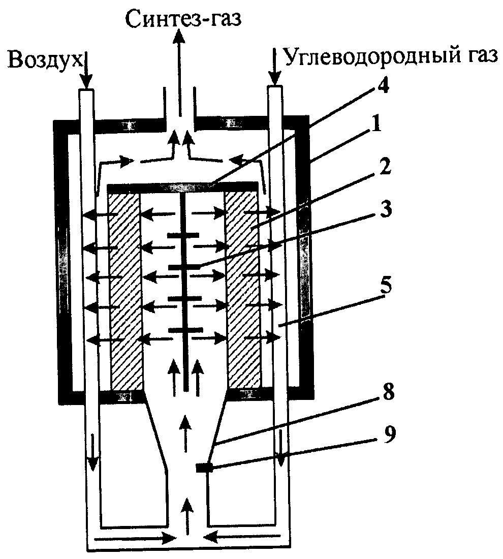
Задачей изобретения является повышение эффективности генерации синтез-газа, упрощение конструкции и эксплуатации устройства при работе в автотермическом режиме. Указанный технический результат достигается тем, что используется генератор синтез-газа (рисунок 1), состоящий из корпуса (1) с расположенным внутри корпуса каталитическим газопроницаемым блоком цилиндрической формы (2). Внутри каталитического блока расположен распределитель газового потока (3), представляющий собой систему закрепленных на общей оси дисков разного диаметра, обеспечивающую выравнивание неоднородности газового потока через стенку каталитического блока. Распределитель газового потока крепится к газонепроницаемому стальному диску (4), расположенному на противоположном входу потока газов обрезе каталитического блока. Газовый поток подается по оси каталитического блока и движется радиально через стенки цилиндрического каталитического блока, проходя через каталитический блок, при этом углеводородный газ окисляется в синтез-газа. Продукты реакции за счет конвективного теплообмена нагревают воздух и углеводородный газ, поступающие на конверсию. Теплообменное устройство располагается в корпусе генератора и представляет собой трубки (5), изготовленные из жаропрочного материала расположенные между внутренней поверхностью корпуса генератора и внешней поверхностью каталитического блока. Или теплообменное устройство (6) (рисунок 2) может находиться вне корпуса генератора с подводом продуктов реакции через теплоизолированный трубопровод (7). Генератор снабжен смесителем (8) и запальным устройством (9). Нагретые воздух и углеводородсодержащий газ пройдя теплообменник (5) или (6), подаются в смеситель, где смешиваются, после чего газовый поток поступает в каталитический блок.The objective of the invention is to increase the efficiency of synthesis gas generation, simplifying the design and operation of the device when operating in an autothermal mode. The specified technical result is achieved by the fact that a synthesis gas generator is used (Figure 1), consisting of a housing (1) with a catalytic gas-permeable block of cylindrical shape located inside the housing (2). A gas flow distributor (3) is located inside the catalytic block, which is a system of disks of different diameters fixed on the common axis, which ensures the smoothing of the inhomogeneity of the gas stream through the wall of the catalytic block. The gas flow distributor is attached to a gas-tight steel disk (4) located at the opposite end of the gas stream and cut off the catalytic block. The gas stream is fed along the axis of the catalytic block and moves radially through the walls of the cylindrical catalytic block, passing through the catalytic block, while the hydrocarbon gas is oxidized into synthesis gas. The reaction products due to convective heat transfer heat the air and hydrocarbon gas entering the conversion. The heat exchange device is located in the generator housing and is a tube (5) made of heat-resistant material located between the inner surface of the generator housing and the outer surface of the catalytic block. Or, the heat exchange device (6) (Figure 2) may be located outside the generator housing with the supply of reaction products through a heat-insulated pipeline (7). The generator is equipped with a mixer (8) and an ignition device (9). Heated air and hydrocarbon-containing gas passing through the heat exchanger (5) or (6) are supplied to the mixer, where they are mixed, after which the gas stream enters the catalytic unit.
Каталитический блок так же может быть выполнен в виде газопроницаемого цилиндра и может представлять собой монолитное изделие с газовыми каналами, полученное самораспространяющимся высокотемпературным синтезом (СВС), гидротермальными способом или другим способом. Каталитический блок может быть выполнен в виде двух металлических цилиндров (рисунок 3) из жаростойкого сплава с перфорированными стенками, а гранулированный катализатор (9) размещается между внешней поверхностью малого цилиндра с внешним радиусом r1 (10) и внутренней поверхностью большого цилиндра с внутренним радиусом r2 (11). Геометрический размер гранул L катализатора должен быть L≤(r2-r1)/10. Верхнее сечение (4) выполнено из газонепроницаемого материала, и диаметром равным диаметру большого цилиндра и предусматривается крепление распределительно устройства (3) (рисунки 1, 2).The catalytic unit can also be made in the form of a gas-permeable cylinder and can be a monolithic product with gas channels obtained by self-propagating high-temperature synthesis (SHS), hydrothermal method or other method. The catalytic unit can be made in the form of two metal cylinders (Figure 3) from a heat-resistant alloy with perforated walls, and the granular catalyst (9) is placed between the outer surface of a small cylinder with an external radius r 1 (10) and the inner surface of a large cylinder with an internal radius r 2 (11). The geometric granule size L of the catalyst should be L≤ (r 2 -r 1 ) / 10. The upper section (4) is made of a gas-tight material, and with a diameter equal to the diameter of the large cylinder, and it is envisaged to mount the distribution device (3) (Figures 1, 2).
Устройство работает следующим образом: исходные реагенты - углеводородный газ и воздух подаются в штуцера входа воздуха и углеводородного газа, соответственно, в объемных соотношениях воздух/углеводородный газ = 8,0-10,0/1. В смесителе происходит перемешивание газов, далее смесь попадает в зону нагретой запальной свечой, смесь воспламеняется и продукты сгорания (дымовые газы) разогревают каталитический блок, при разогреве каталитического блока до температуры (550-650°C), при которой реакция парциального окисления может протекать в автотермическом режиме. После чего изменяется соотношение воздух углеводородный газ до 4,0-2,5/1 объемных (оптимальных для генерации синтез-газа). В стационарном режиме работы генератора синтез-газа радиального типа (режим генерации синтез-газа) за счет использования теплообменников происходит рекуперация тепла, так воздух и углеводородный газ, поступающие на конверсию, нагреваются за счет конвективной теплопередачи тепла продуктов реакции во встроенном в корпус генератора теплообменнике (5) или вынесенном теплообменнике (6). Разогретые газы смешиваются в смесители и поток поступает в каталитический блок, в замкнутом объеме внутри каталитического блока происходит дополнительный подогрев газо-воздушной смеси ИК-излучением, исходящим от разогретого катализатора. Рекуперация тепла при проведении процесса необходимо по следующим причинам. Процесс парциального окисления углеводородов на примере метана состоит из нескольких стадий:The device operates as follows: the initial reagents are hydrocarbon gas and air are supplied to the air inlet and hydrocarbon gas fittings, respectively, in air / hydrocarbon gas volume ratios = 8.0-10.0 / 1. The gas is mixed in the mixer, then the mixture enters the zone with a heated spark plug, the mixture ignites and the combustion products (flue gases) heat up the catalytic unit, when the catalytic unit is heated to a temperature (550-650 ° C), at which the partial oxidation reaction can proceed autothermal mode. After that, the air-hydrocarbon gas ratio changes to 4.0-2.5 / 1 volumetric (optimal for the synthesis gas generation). In the stationary mode of operation of the radial type synthesis gas generator (synthesis gas generation mode), heat is recovered through the use of heat exchangers, so the air and hydrocarbon gas supplied to the conversion are heated by convective heat transfer of the reaction products in the heat exchanger built into the generator body ( 5) or a remote heat exchanger (6). The heated gases are mixed into the mixers and the stream enters the catalytic unit, in a closed volume inside the catalytic unit, the gas-air mixture is additionally heated by infrared radiation emanating from the heated catalyst. Heat recovery during the process is necessary for the following reasons. The process of partial oxidation of hydrocarbons using methane as an example consists of several stages:
1. CH4+O2=CO2+2H2O+802 кДж/моль1. CH 4 + O 2 = CO 2 + 2H 2 O + 802 kJ / mol
2. CH4+CO2=2CO+2H2-261 кДж/моль2. CH 4 + CO 2 = 2CO + 2H 2 -261 kJ / mol
3. CH4+H2O=CO+3H2-226 кДж/моль3. CH 4 + H 2 O = CO + 3H 2 -226 kJ / mol
4. 2CH4+O2=2CO+4H2+70 кДж/моль4. 2CH 4 + O 2 = 2CO + 4H 2 +70 kJ / mol
На первой стадии происходит глубокое окисление части метана до углекислого газа и воды с выделением тепла (реакция 1), продукты глубокого окисления углекислый газ и вода взаимодействуют с остаточным метаном с образованием синтез-газа (реакции 2, 3) - эти реакции протекают с поглощением тепла, суммарный процесс парциального окисления синтез газа можно представить уравнением 4, и он характеризуется небольшим тепловыделением. Для обеспечения эффективности процесса парциального окисления и для сохранения теплового баланса генератора и полноты конверсии метана используется прием рекуперации тепла, позволяющий вносить дополнительную энергию в каталитический процесс за счет разогретой газо-воздушной смеси, поступающей на катализатор.At the first stage, a part of methane is deeply oxidized to carbon dioxide and water with heat evolution (reaction 1), products of deep oxidation of carbon dioxide and water interact with residual methane to produce synthesis gas (reactions 2, 3) - these reactions proceed with heat absorption , the total process of partial oxidation of gas synthesis can be represented by equation 4, and it is characterized by a small heat release. To ensure the efficiency of the partial oxidation process and to maintain the heat balance of the generator and the complete conversion of methane, a heat recovery technique is used, which makes it possible to add additional energy to the catalytic process due to the heated gas-air mixture supplied to the catalyst.
Использование полезной модели иллюстрируется следующими примерами:Using the utility model is illustrated by the following examples:
Пример 1. Используется генератор синтез-газа с теплообменными трубками расположенными внутри корпуса (рис.1). Используется катализатор, полученный СВС синтезом химического состава 50% мас Ni и 50% мас оксидов алюминия и магния. Катализатор представляет собой пористый цилиндр с внешним диаметром 0,07 м, и толщиной стенки 0,025 м, высота 0,09 м, цилиндр закрыт с торца газонепроницаемым стальным диском внешним диаметром 0,07 м. Подается воздух в количестве 25,8 л/мин и углеводородный газ состава 95,0% об метана, остальное этан, пропан и бутан расход углеводородного газа 3,0 л/мин, соотношение воздух/углеводородный газ = 8,6:1. Приводится в действие запальное устройство. После разогрева каталитического блока дымовыми газами до температуры 600°C, изменяются расходы газов, которые составляют для воздуха 57,4 л/мин и для углеводородного газа 20,5 л/мин, соотношении воздух / углеводородный газ = 2,8:1. При стабилизации температуры катализатора Тк=845°C и смеси газов поступающих на катализатор Тг=121°C, получается синтез-газ с содержанием CO - 16,5% об, и H2 - 31,0% об.Example 1. A synthesis gas generator is used with heat exchange tubes located inside the housing (Fig. 1). The catalyst obtained by SHS is used to synthesize the chemical composition of 50 wt% Ni and 50 wt% aluminum and magnesium oxides. The catalyst is a porous cylinder with an external diameter of 0.07 m, and a wall thickness of 0.025 m, a height of 0.09 m, the cylinder is closed at the end with a gas-tight steel disk with an external diameter of 0.07 m. Air is supplied in an amount of 25.8 l / min and hydrocarbon gas with a composition of 95.0% of methane, the rest is ethane, propane and butane; the flow rate of hydrocarbon gas is 3.0 l / min; the ratio of air / hydrocarbon gas = 8.6: 1. The ignition device is driven. After heating the catalytic unit with flue gases to a temperature of 600 ° C, the gas flow rate changes, which are 57.4 l / min for air and 20.5 l / min for hydrocarbon gas, air / hydrocarbon gas ratio = 2.8: 1. When stabilizing the temperature of the catalyst Tk = 845 ° C and the mixture of gases entering the catalyst Tg = 121 ° C, a synthesis gas with a CO content of 16.5% vol. And H 2 31.0% vol.
Пример 2. Используется генератор синтез-газа радиального типа с вынесенным теплообменником (рис.2). Используется катализатор аналогичный примеру 1. Подача газов и запуск устройства аналогичен примеру 1. Подается воздух в количестве 59,8 л/мин и углеводородный газ 23,0 л/мин, соотношении воздух/углеводородный газ = 2,6:1. Температура смеси газов поступающих на катализатор составила Тг=123°C, температура каталитического блока составила Тк=814°C. Синтез-газ получаемый в генераторе содержит CO - 16,4% об, и H2 - 32,1% об.Example 2. A radial-type synthesis gas generator with a remote heat exchanger is used (Fig. 2). A catalyst is used similar to Example 1. The gas supply and start-up of the device are similar to Example 1. Air is supplied in an amount of 59.8 l / min and hydrocarbon gas 23.0 l / min, air / hydrocarbon gas ratio = 2.6: 1. The temperature of the mixture of gases entering the catalyst was Tg = 123 ° C, the temperature of the catalytic block was Tk = 814 ° C. The synthesis gas obtained in the generator contains CO - 16.4% vol., And H 2 - 32.1% vol.
Пример 3. Используется генератор аналогичный примеру 1. Каталитический блок состоит из перфорированного внутреннего цилиндра с внешним радиусом r1=0,011 м и высотой 0,11 м, и перфорированного внешнего цилиндра с внутренним радиусом r2=0,036 м с высотой 0,11 м. Сборка цилиндров закрывается стальным диском радиусом 0,04 м. Между цилиндрами засыпан катализатор с размером гранул 0,02-0,025 м, состава 15% масс Ni остальное оксид алюминия и циркония. Подача газов и запуск устройства аналогичен примеру 1. Подается воздух в количестве 55,4 л/мин и углеводородный газ с расходом 20,5 л/мин, соотношении воздух/углеводородный газ = 2,7:1. Температура смеси газов поступающих на катализатор составила Тг=112°C, температура каталитического блока составила Тк=800°C. Синтез-газ получаемый в генераторе содержит CO - 16,8% об, и H2 - 32,5% об.Example 3. A generator is used similar to example 1. The catalytic unit consists of a perforated inner cylinder with an external radius r 1 = 0.011 m and a height of 0.11 m, and a perforated external cylinder with an internal radius r 2 = 0.036 m with a height of 0.11 m. The cylinder assembly is closed by a steel disk with a radius of 0.04 m. Between the cylinders, a catalyst is filled with a particle size of 0.02-0.025 m, composition 15% of the mass of Ni, the rest is aluminum oxide and zirconium. The gas supply and start-up of the device is similar to example 1. Air is supplied in an amount of 55.4 l / min and hydrocarbon gas with a flow rate of 20.5 l / min, air / hydrocarbon gas ratio = 2.7: 1. The temperature of the mixture of gases entering the catalyst was Tg = 112 ° C, the temperature of the catalytic block was Tk = 800 ° C. The synthesis gas obtained in the generator contains CO - 16.8% vol., And H 2 - 32.5% vol.
Пример 4. Используется генератор аналогичный примеру 2. Каталитический блок и применяемый катализатор аналогичен примеру 3. Подается воздух с расходом 38,0 л/мин и углеводородный газ с расходом 4,0 л/мин, соотношение воздух/углеводородный газ = 9,5 объемных. Приводится в действие запальное устройство. После разогрева каталитического блока дымовыми газами до температуры 570°C, изменяются расходы газов, которые составляют для воздуха 53,5 л/мин и для углеводородного газа 17,8 л/мин, соотношении воздух/углеводородный газ = 3,0:1. При стабилизации температуры катализатора Тк=854°C и смеси газов Тг=138°C поступающих на катализатор, на выходе из генератора синтез-газ содержит CO - 15,7% об, и H2 - 30,1% об.Example 4. A generator is used similar to example 2. The catalytic unit and the used catalyst are similar to example 3. Air is supplied with a flow rate of 38.0 l / min and hydrocarbon gas with a flow rate of 4.0 l / min, air / hydrocarbon gas ratio = 9.5 volume . The ignition device is driven. After heating the catalytic unit with flue gases to a temperature of 570 ° C, the gas flow rates change, which are 53.5 l / min for air and 17.8 l / min for hydrocarbon gas, air / hydrocarbon gas ratio = 3.0: 1. When stabilizing the temperature of the catalyst Tk = 854 ° C and a mixture of gases Tg = 138 ° C entering the catalyst, the synthesis gas at the outlet of the generator contains CO - 15.7% vol., And H 2 - 30.1% vol.
Как следует из представленных примеров, предлагаемое техническое решение обеспечивает достижение следующего технического результата: эффективность работы генератора, высокие концентрации получаемого синтез-газа, простота эксплуатации генератора синтез-газа радиального типа, управление режимами работы генератора осуществляется изменением расходов воздуха и углеводородного газа.As follows from the presented examples, the proposed technical solution ensures the achievement of the following technical result: generator efficiency, high concentrations of the resulting synthesis gas, ease of operation of the radial type synthesis gas generator, and control of the generator operating modes by changing the air and hydrocarbon gas flow rates.
Claims (5)
Priority Applications (1)
| Application Number | Priority Date | Filing Date | Title |
|---|---|---|---|
| RU2011141361/05U RU120092U1 (en) | 2011-10-12 | 2011-10-12 | CATALYTIC SYNTHESIS GAS GENERATOR RADIAL TYPE |
Applications Claiming Priority (1)
| Application Number | Priority Date | Filing Date | Title |
|---|---|---|---|
| RU2011141361/05U RU120092U1 (en) | 2011-10-12 | 2011-10-12 | CATALYTIC SYNTHESIS GAS GENERATOR RADIAL TYPE |
Publications (1)
| Publication Number | Publication Date |
|---|---|
| RU120092U1 true RU120092U1 (en) | 2012-09-10 |
Family
ID=46939208
Family Applications (1)
| Application Number | Title | Priority Date | Filing Date |
|---|---|---|---|
| RU2011141361/05U RU120092U1 (en) | 2011-10-12 | 2011-10-12 | CATALYTIC SYNTHESIS GAS GENERATOR RADIAL TYPE |
Country Status (1)
| Country | Link |
|---|---|
| RU (1) | RU120092U1 (en) |
Cited By (2)
| Publication number | Priority date | Publication date | Assignee | Title |
|---|---|---|---|---|
| RU2554577C2 (en) * | 2013-03-15 | 2015-06-27 | Федеральное государственное бюджетное учреждение науки Институт химической физики им. Н.Н. Семенова Российской академии наук (ИХФ РАН) | Synthetic gas production method |
| RU2574254C1 (en) * | 2014-10-27 | 2016-02-10 | Михаил Геннадьевич Чуканин | Method for obtaining synthesis-gas and device for realisation thereof |
-
2011
- 2011-10-12 RU RU2011141361/05U patent/RU120092U1/en active
Cited By (2)
| Publication number | Priority date | Publication date | Assignee | Title |
|---|---|---|---|---|
| RU2554577C2 (en) * | 2013-03-15 | 2015-06-27 | Федеральное государственное бюджетное учреждение науки Институт химической физики им. Н.Н. Семенова Российской академии наук (ИХФ РАН) | Synthetic gas production method |
| RU2574254C1 (en) * | 2014-10-27 | 2016-02-10 | Михаил Геннадьевич Чуканин | Method for obtaining synthesis-gas and device for realisation thereof |
Similar Documents
| Publication | Publication Date | Title |
|---|---|---|
| CA3115358C (en) | Method and reactor for producing one or more products | |
| RU2415073C2 (en) | Compact reforming reactor | |
| RU2411075C2 (en) | Compact reforming reactor | |
| US20080031800A1 (en) | Process and apparatus for generating hydrogen | |
| US6881394B2 (en) | Steam reformer for methane with internal hydrogen separation and combustion | |
| US8133445B2 (en) | Reaction chamber promoting heat exchange between the reagents and the gases that are produced | |
| RU2374173C1 (en) | Method of producing synthetic gas | |
| RU120092U1 (en) | CATALYTIC SYNTHESIS GAS GENERATOR RADIAL TYPE | |
| RU2372277C1 (en) | Method of producing hydrogen and device to this end | |
| Dai et al. | Efficient reforming of methane in a porous radiant reactor with regular structure: A novel experimental system for heat-hydrogen coproduction | |
| Palma et al. | Hydrogen production by natural gas in a compact ATR-based kW-scale fuel processor | |
| RU2286308C2 (en) | Radial type device for production of the synthesis gas | |
| WO2012112065A1 (en) | Method and device for generating synthesis gas | |
| RU2615768C1 (en) | Reactor for catalytic steam and steam-carbon-dioxide hydrocarbon conversion | |
| EP1779925B1 (en) | Catalytic reactor for endothermic reaction processes, particularly for light hydrocarbon steam reforming | |
| US10888833B2 (en) | Reactor for producing synthesis gas | |
| RU142113U1 (en) | CATALYTIC SYNTHESIS GAS GENERATOR | |
| RU2574254C1 (en) | Method for obtaining synthesis-gas and device for realisation thereof | |
| Dmitrenko et al. | Methane-to-hydrogen conversion in the filtration-combustion wave of rich methane-air mixtures | |
| RU2796425C1 (en) | Synthesis gas reactor and method for producing synthesis gas in synthesis gas reactor | |
| US20220194788A1 (en) | Plant for the production of hydrogen from any hydrocarbon gases | |
| CN201762094U (en) | Distributed natural gas hydrogen-making reactor | |
| RU2320533C2 (en) | Method of steam catalytic conversion of natural gas into synthesis-gas and device for realization of this method | |
| RU2574464C1 (en) | Method for obtaining synthesis-gas from hydrogen-containing raw material in revere flow reactor and reactor for realisation thereof | |
| Chen et al. | Hydrogen-assisted catalytic ignition characteristics of propane–air with a chemical kinetic model in a Pt/γ-Al 2 O 3 micro-combustor in different feeding modes |