RU110783U1 - CONSTRUCTION CONNECTION ASSEMBLY - Google Patents
CONSTRUCTION CONNECTION ASSEMBLY Download PDFInfo
- Publication number
- RU110783U1 RU110783U1 RU2011130678/03U RU2011130678U RU110783U1 RU 110783 U1 RU110783 U1 RU 110783U1 RU 2011130678/03 U RU2011130678/03 U RU 2011130678/03U RU 2011130678 U RU2011130678 U RU 2011130678U RU 110783 U1 RU110783 U1 RU 110783U1
- Authority
- RU
- Russia
- Prior art keywords
- reinforcing
- guides
- reinforced concrete
- shaped
- loop
- Prior art date
Links
Landscapes
- Reinforcement Elements For Buildings (AREA)
Abstract
1. Узел сопряжения строительных конструкций, содержащий конструктивные элементы узла сопряжения и элементы их соединения, отличающийся тем, что конструктивные элементы узла сопряжения представляют собой вертикальную внутреннюю несущую железобетонную панель, горизонтальную несущую железобетонную балку и горизонтальную пустотную железобетонную плиту перекрытия, элементы соединения состоят из арматурных петлеобразных выпусков, арматурных петлеобразных направляющих, арматурных стержней и дополнительного соединительного элемента, при этом конструктивные элементы узла соединены с использованием единого вертикального объемного арматурного каркаса, размещенного внутри вертикальной внутренней несущей железобетонной панели, состоящего из арматурных петлеобразных направляющих, арматурных петлеобразных выпусков, выходящих из железобетонной балки с образованием при пересечении с арматурными направляющими панели кольцеобразных направляющих каркаса, и арматурных стержней, размещенных на всех направляющих каркаса и соединенных с ними дополнительным соединительным элементом, при этом пустоты узла сопряжения забетонированы вертикально с образованием монолитной шпонки узла сопряжения. ! 2. Узел по п.1, отличающийся тем, что арматурные петлеобразные направляющие, арматурные петлеобразные выпуски и арматурные стержни образуют систему направляющих, препятствующих прогрессирующему обрушению. ! 3. Узел по любому из пп.1 и 2, отличающийся тем, что в качестве дополнительного соединительного элемента используют вязальную проволоку. 1. The junction of building structures containing the structural elements of the interface and the elements of their connection, characterized in that the structural elements of the interface are a vertical inner supporting reinforced concrete panel, a horizontal supporting reinforced concrete beam and a horizontal hollow reinforced concrete floor slab, the connection elements consist of reinforced loop-shaped outlets, reinforcing loop-shaped guides, reinforcing bars and an additional connecting element, p At the same time, the structural elements of the assembly are connected using a single vertical volumetric reinforcing cage located inside the vertical internal supporting reinforced concrete panel, consisting of reinforcing loop-shaped guides, reinforcing loop-shaped outlets emerging from the reinforced concrete beam with the formation of ring-shaped guide rails of the frame and reinforcing bars at the intersection with the reinforcing guides of the panel rods placed on all guides of the frame and connected to them by an additional connecting element, while the voids of the interface node are concreted vertically with the formation of a monolithic key of the interface node. ! 2. The node according to claim 1, characterized in that the reinforcing loop-shaped guides, reinforcing loop-shaped outlets and reinforcing bars form a system of guides that prevent progressive collapse. ! 3. An assembly according to any one of claims 1 and 2, characterized in that a knitting wire is used as an additional connecting element.
Description
Полезная модель относится к области строительства, в частности, панельному домостроению и может быть использована при проектировании и возведении зданий и сооружений как жилого, так и социального назначения, предназначенных к эксплуатации в том числе, в зонах с повышенной сейсмической активностью.The utility model relates to the field of construction, in particular, panel housing construction and can be used in the design and construction of buildings and structures, both residential and social, intended for use, including in areas with increased seismic activity.
Из уровня техники известны решения аналогичного характера.The prior art solutions of a similar nature.
Известен узел сопряжения железобетонных многопустотных плит (RU 2363819, E04B 1/61, 10.08.2009 г.). Плиты, сопряженные с несущим железобетонным ригелем, выполнены с двумя пазами. Пазы обращены друг к другу в области межплитного шва и образованы на месте пустот до их донной части. Плиты имеют выпуски арматуры, обращенные в область межплитного шва. Параллельно торцевой поверхности в каждой плите размещены металлические стержни, связанные друг с другом тяжами с крюками на концах, зацепленными за стержни. Тяжи выполнены составными и сопряжены между собой в области межплитного шва. По краям плит размещены две пары параллельных продольных арматурных стержней. Один из продольных арматурных стержней каждой пары размещен в верхней части перемычки плиты, а другой - под ним в нижней части этой же перемычки. Каждая пара стержней образована единым стержнем, пропущенным через перемычку и образующим стежок на поверхности перемычки по ее высоте. Между верхним и нижним стержнями каждой пары размещена зигзагообразная проволока. Проволока скреплена в отдельных местах с теми продольными арматурными стержнями, с которыми она соприкасается. Несущий железобетонный ригель имеет арматурные выпуски продольной арматуры и поперечные арматурные стержни, которые размещены над продольными и с которыми связаны дополнительно введенные петлеобразные арматурные элементы. В межплитном шве над железобетонным ригелем размещен арматурный каркас по всей длине шва. Высота петлеобразных арматурных элементов не превышает высоты арматурного каркаса. Ширина петлеобразных арматурных элементов не превышает ширины того же арматурного каркаса.Known interface unit for reinforced concrete hollow core slabs (RU 2363819, E04B 1/61, 08/10/2009). Slabs coupled with a bearing reinforced concrete crossbar are made with two grooves. The grooves face each other in the area of the interplate seam and are formed in the place of voids to their bottom. The plates have rebar outlets facing the area of the inter-plate seam. Parallel to the end surface, in each plate, metal rods are placed, connected to each other by strands with hooks at the ends, hooked to the rods. The rods are made integral and are interconnected in the area of the interplate seam. Along the edges of the plates are two pairs of parallel longitudinal reinforcing bars. One of the longitudinal reinforcing bars of each pair is located in the upper part of the plate jumper, and the other is underneath in the lower part of the same jumper. Each pair of rods is formed by a single rod, passed through the jumper and forming a stitch on the surface of the jumper along its height. Between the upper and lower rods of each pair there is a zigzag wire. The wire is fastened in separate places with those longitudinal reinforcing bars with which it is in contact. The bearing reinforced concrete crossbar has reinforcing outlets of longitudinal reinforcement and transverse reinforcing bars that are placed above the longitudinal reinforcing bars and with which additionally introduced loop-shaped reinforcing elements are connected. In the interplate seam above the reinforced concrete crossbar, a reinforcing cage is placed along the entire length of the seam. The height of the loop-shaped reinforcing elements does not exceed the height of the reinforcing cage. The width of the loop-shaped reinforcing elements does not exceed the width of the same reinforcing cage.
Также из уровня техники известен узел сопряжения многопустотных плит перекрытия с ригелями (RU 81227, E04B 1/61, 10.03.2009 г.), содержащий установленные на опорных элементах колонн ригели с полками, многопустотные плиты перекрытия с консолями для расположения их на полках ригеля и элементами для образования металлических связей. Высота полок ригеля выполнена соразмерной расстоянию от нижней поверхности многопустотной плиты перекрытия до опорной поверхности консоли, например, равному половине толщины многопустотной плиты перекрытия. Консоли многопустотных плит перекрытия упрочнены арматурными каркасами, выполненными в виде сварных решеток, вертикально установленных в приторцовых участках многопустотной плиты перекрытия и в межпустотных пространствах, свободных от предварительно напряженных стержней. Ригели узла снабжены закладными деталями, расположенными или в углублениях на верхней его поверхности, или на боковых его поверхностях. Элементы для образования металлических связей многопустотных плит выполнены в виде закладных деталей, расположенных на верхней поверхности многопустотных плит перекрытия, а металлические связи, имеющие вид стержней или пластин, выполнены с возможностью соединения многопустотных плит перекрытия с ригелем сваркой по упомянутым закладным деталям и связывающие противолежащие относительно ригеля многопустотные плиты перекрытия. Сварные решетки включают заанкерованный стержень с отгибами по концам и связанные поперечными хомутами стержни продольной арматуры, причем верхний и укороченный средний стержни размещены над опорной поверхностью консоли, а нижний стержень - между торцевыми стенками многопустотной плиты перекрытия и ниже опорной поверхности консоли.Also known from the prior art is a node for interlocking multi-hollow floor slabs with crossbars (RU 81227, E04B 1/61, 03/10/2009), comprising crossbars with shelves mounted on the supporting elements of the columns, multi-hollow floor slabs with consoles for positioning them on the shelves of the crossbar and elements for the formation of metal bonds. The height of the shelves of the crossbar is made commensurate with the distance from the lower surface of the multi-hollow floor slab to the supporting surface of the console, for example, equal to half the thickness of the multi-hollow floor slab. The consoles of multi-hollow floor slabs are reinforced with reinforcing frames made in the form of welded gratings, vertically installed in the side sections of the multi-hollow floor slab and in hollow spaces free of prestressed rods. Crossbars of the assembly are equipped with embedded parts located either in recesses on its upper surface or on its lateral surfaces. Elements for forming metal bonds of multi-hollow plates are made in the form of embedded parts located on the upper surface of multi-hollow floor slabs, and metal bonds having the form of rods or plates are made with the possibility of connecting multi-hollow floor plates with a crossbar by welding along the mentioned embedded parts and connecting opposite ones relative to the crossbar hollow core slabs. Welded gratings include an anchored rod with bends at the ends and rods of longitudinal reinforcement connected by transverse clamps, the upper and shortened middle rods being placed above the supporting surface of the console, and the lower rod between the end walls of the multi-hollow floor slab and below the supporting surface of the console.
Кроме того, из уровня техники известен узел для сопряжения железобетонных многопустотных плит в сборно-монолитных перекрытиях с несущими железобетонными ригелями, предназначенных для использования при строительстве зданий в сейсмоопасных районах (RU 74935, E04B 1/61, 20.07.2008 г., ближайший аналог). Согласно данному решению железобетонные многопустотные плиты, сопряженные с несущим железобетонным ригелем, выполнены с двумя пазами, обращенными друг к другу в области межплитного шва и образованными на месте пустот до их донной части, железобетонные многопустотные плиты имеют выпуски арматуры, обращенные также в область межплитного шва, параллельно торцевой поверхности в каждой плите размещены металлические стержни, связанные друг с другом тяжами с крюками, на концах зацепленными за стержни. Тяжи выполнены составными и сопряжены между собой в области межплитного шва, по краям плит размещены две пары параллельных продольных арматурных стержней,. Один из продольных арматурных стержней каждой пары размещен в верхней части перемычки пустотной плиты, а другой - под ним в нижней части этой же перемычки. Каждая пара стержней образована единым стержнем, пропущенным через перемычку и образующим стежок поверх перемычки, между верхним и нижним стержнями каждой пары размещена зигзагообразная проволока, в отдельных местах скрепленная с теми продольными арматурными стержнями, с которыми она соприкасается. Несущий железобетонный ригель, с которым сопряжены вышеуказанные железобетонные многопустотные плиты, также имеет арматурные выпуски продольной арматуры и поперечные арматурные стержни, которые размещены над продольными и с которыми связаны дополнительно введенные петлеобразные арматурные элементы, в межплитном шве над железобетонным ригелем размещен арматурный каркас по всей длине шва, высота петлеобразных арматурных элементов не превышает высоты арматурного каркаса, а его ширина не превышает ширины вышеуказанного арматурного каркаса.In addition, a knot for interfacing reinforced concrete multi-hollow slabs in prefabricated monolithic floors with load-bearing reinforced concrete crossbars intended for use in the construction of buildings in earthquake-prone areas is known from the prior art (RU 74935, E04B 1/61, 07.20.2008, closest analogue) . According to this decision, reinforced concrete multi-hollow slabs conjugated with a bearing reinforced concrete crossbar are made with two grooves facing each other in the area of the inter-plate seam and formed at the place of voids to their bottom, reinforced concrete multi-hollow plates have outlets of reinforcement also facing the area of the inter-plate seam, parallel to the end surface, in each plate, metal rods are placed, connected to each other by strands with hooks, hooked at the ends to the rods. The rods are made integral and mated to each other in the area of the inter-plate seam, along the edges of the plates are two pairs of parallel longitudinal reinforcing bars. One of the longitudinal reinforcing bars of each pair is located in the upper part of the jumper of the hollow core, and the other is underneath in the lower part of the same jumper. Each pair of rods is formed by a single rod, passed through the jumper and forming a stitch on top of the jumper, between the upper and lower rods of each pair a zigzag wire is placed, in some places bonded to those longitudinal reinforcing bars with which it is in contact. The bearing reinforced concrete crossbar, with which the above reinforced concrete multi-hollow slabs are interfaced, also has reinforcing outlets of longitudinal reinforcement and transverse reinforcing bars that are placed above the longitudinal reinforcing elements and with which additionally introduced loop-shaped reinforcing elements are connected; , the height of the loop-shaped reinforcing elements does not exceed the height of the reinforcing cage, and its width does not exceed the width of the above reinforcing rkasa.
Недостаток, присущий каждому из перечисленных выше технических решений, заключается в недостаточно высокой способности узлов сопротивляться сейсмическим нагрузкам и, как следствие, недостаточно высокая сейсмоустойчивость (способность выдерживать землетрясения с минимальными повреждениями) зданий и сооружений, возводимых согласно указанным выше технологиям.The disadvantage inherent in each of the above technical solutions is the insufficiently high ability of nodes to resist seismic loads and, as a consequence, insufficiently high seismic stability (ability to withstand earthquakes with minimal damage) of buildings and structures constructed according to the above technologies.
Более того, перечисленные узлы излишне конструктивно усложнены и, как следствие, материалоемки, что также является их существенным недостатком, т.к. с одной стороны приводит к удорожанию стоимости узла, другой - увеличению сроков его сборки. Использование сварочных операций при сборке узлов также является негативным технологическим моментом - т.к. приводит к увеличению сроков сборки узлов и, что очень важно, снижению долговечности узлов (зданий, сооружений), из-за преждевременной коррозии элементов узла сопряжения.Moreover, the listed nodes are unnecessarily structurally complicated and, as a consequence, material-intensive, which is also their significant drawback, because on the one hand, it leads to an increase in the cost of the unit, and on the other, an increase in the time for its assembly. The use of welding operations in the assembly of nodes is also a negative technological moment - because leads to an increase in the assembly time of the nodes and, very importantly, a decrease in the durability of the nodes (buildings, structures), due to premature corrosion of the elements of the interface node.
Задача, на решение которой направлено данное техническое решение, заключается в создании нового узла сопряжения строительных конструкций, позволяющего устранить указанные выше недостатки.The problem to which this technical solution is directed is to create a new node for interfacing building structures, which allows to eliminate the above disadvantages.
Технический результат заключается в повышении сейсмоустойчивых свойств узла сопряжения строительных конструкций, что приведет к повышению характеристик сейсмоустойчивости зданий и сооружений, возводимых с использованием данной полезной модели. Упрощение конструкции узла, снижение материалоемкости, и, как следствие сокращение сроков его сборки также являются достигаемыми при осуществлении данной полезной модели техническими результатами. Не последнее значение отводится и повышению долговечности зданий и сооружений, возведенных с использованием данной полезной модели.The technical result consists in increasing the earthquake-resistant properties of the interface unit of building structures, which will lead to an increase in the seismic stability characteristics of buildings and structures constructed using this utility model. Simplification of the assembly design, reduction of material consumption, and, as a result, reduction of its assembly time are also technical results achieved by implementing this utility model. Not the least importance is given to increasing the durability of buildings and structures erected using this utility model.
Решение указанной выше задачи достигается следующим образом.The solution to the above problem is achieved as follows.
Узел сопряжения строительных конструкций содержит конструктивные элементы узла сопряжения и элементы их соединения. Конструктивные элементы узла сопряжения представляют собой вертикальную внутреннюю несущую железобетонную панель, горизонтальную несущую железобетонную балку и горизонтальную пустотную железобетонную плиту перекрытия. Элементы соединения состоят из арматурных петлеобразных выпусков, арматурных петлеобразных направляющих, арматурных стержней и дополнительного соединительного элемента. Конструктивные элементы узла соединены с использованием единого вертикального объемного арматурного каркаса, размещенного внутри вертикальной внутренней несущей железобетонной панели. Каркас состоит из арматурных петлеобразных направляющих, арматурных петлеобразных выпусков, выходящих из железобетонной балки с образованием при пересечении с арматурными направляющими панели кольцеобразных («0»-образных) направляющих каркаса, и арматурных стержней, размещенных на всех направляющих каркаса и соединенных с ними дополнительным соединительным элементом. Пустоты узла сопряжения забетонированы вертикально с образованием монолитной шпонки узла сопряжения. Арматурные петлеобразные направляющие, арматурные петлеобразные выпуски и арматурные стержни, образуют систему направляющих препятствующих прогрессирующему обрушению. В качестве дополнительного соединительного элемента используют вязальную проволоку.The interface unit of building structures contains structural elements of the interface node and elements of their connection. The structural elements of the interface node are a vertical inner supporting reinforced concrete panel, a horizontal supporting reinforced concrete beam and a horizontal hollow reinforced concrete floor slab. Connection elements consist of reinforcing loop-shaped outlets, reinforcing loop-like guides, reinforcing bars and an additional connecting element. The structural elements of the unit are connected using a single vertical volumetric reinforcing cage, placed inside a vertical internal reinforced concrete supporting panel. The frame consists of reinforcing loop-shaped guides, reinforcing loop-shaped outlets emerging from the reinforced concrete beam with the formation of ring-shaped (“0” -shaped) frame guides when they intersect with the reinforcing guides, and reinforcing bars placed on all the frame guides and connected with them by an additional connecting element . The voids of the interface unit are concreted vertically with the formation of a monolithic key of the interface unit. Reinforcing loop-shaped guides, reinforcing loop-shaped outlets and reinforcing bars form a system of guides that prevent progressive collapse. As an additional connecting element using a knitting wire.
Выполнение одного из конструктивных элементов узла сопряжения пустотным позволяет, в частности, упростить процесс сборки узла и снизить его материалоемкость, сократив при этом время сборки узла в целом.The implementation of one of the structural elements of the coupling node hollow allows, in particular, to simplify the assembly process of the node and reduce its material consumption, while reducing the assembly time of the node as a whole.
Выполнение элементов узла сопряжения с единым вертикальным объемным арматурным каркасом позволяет существенно снизить материалоемкость узла в целом, поскольку это позволяет соединять все конструктивные элементы уза с наименьшими затратами на элементы соединения узла.The implementation of the elements of the interface with a single vertical volumetric reinforcing cage can significantly reduce the material consumption of the node as a whole, since this allows you to connect all structural elements of the bond with the lowest cost for the elements of the connection node.
Кроме того, такое выполнение единого вертикального объемного каркаса и способа соединения всех конструктивных элементов узла позволяет существенно повысить прочностные характеристики узла в целом, что повышает способность узла препятствовать прогрессирующему обрушению.In addition, this embodiment of a single vertical volumetric frame and the method of connecting all structural elements of the node can significantly increase the strength characteristics of the node as a whole, which increases the ability of the node to prevent progressive collapse.
Особая конструкция и взаимосвязь всех элементов соединения, а также ориентированность при расчете конструкции узла сопряжения на возможное прогрессирующее обрушение (обрушение конструкций здания (или его части высотой два и более этажей), потерявших опору в результате локального разрушения какого-либо этажа), позволяет повысить характеристики сейсмоустойчивости узла сопряжения и возводимых с его использованием зданий, сооружений.The special design and interconnection of all the elements of the connection, as well as the orientation when calculating the design of the interface unit for possible progressive collapse (collapse of the building structures (or parts of it with a height of two or more floors) that have lost support as a result of local destruction of any floor), allows to increase the seismic stability of the interface node and buildings and structures being built with its use.
Использование в качестве дополнительного соединительного элемента вязальной проволоки позволяет отказаться от использования сварных соединений конструкций, что приводит к совокупности благоприятных технологических и иных не менее важных последствий: сокращение времени, отведенного на сборку узла, снижение материалоемкости, снижение затрат на сборку узла, повышение долговечности зданий и сооружений, возведенных с использованием узла сопряжения за счет отказа от использования сварки в процессе сборки узла сопряжения (первейших и наиболее опасных очагов коррозии в строительных конструкциях).The use of knitting wire as an additional connecting element makes it possible to abandon the use of welded joints of structures, which leads to a combination of favorable technological and other equally important consequences: reducing the time allotted for assembly of the assembly, reducing material consumption, reducing assembly assembly costs, increasing the durability of buildings and structures erected using the interface unit due to the refusal to use welding in the assembly process of the interface unit (the first and more dangerous of corrosion in structures).
Ниже приводится описание графических материалов, никоим образом не ограничивающее все возможные варианты осуществления полезной модели.Below is a description of the graphic materials, in no way limiting all possible embodiments of the utility model.
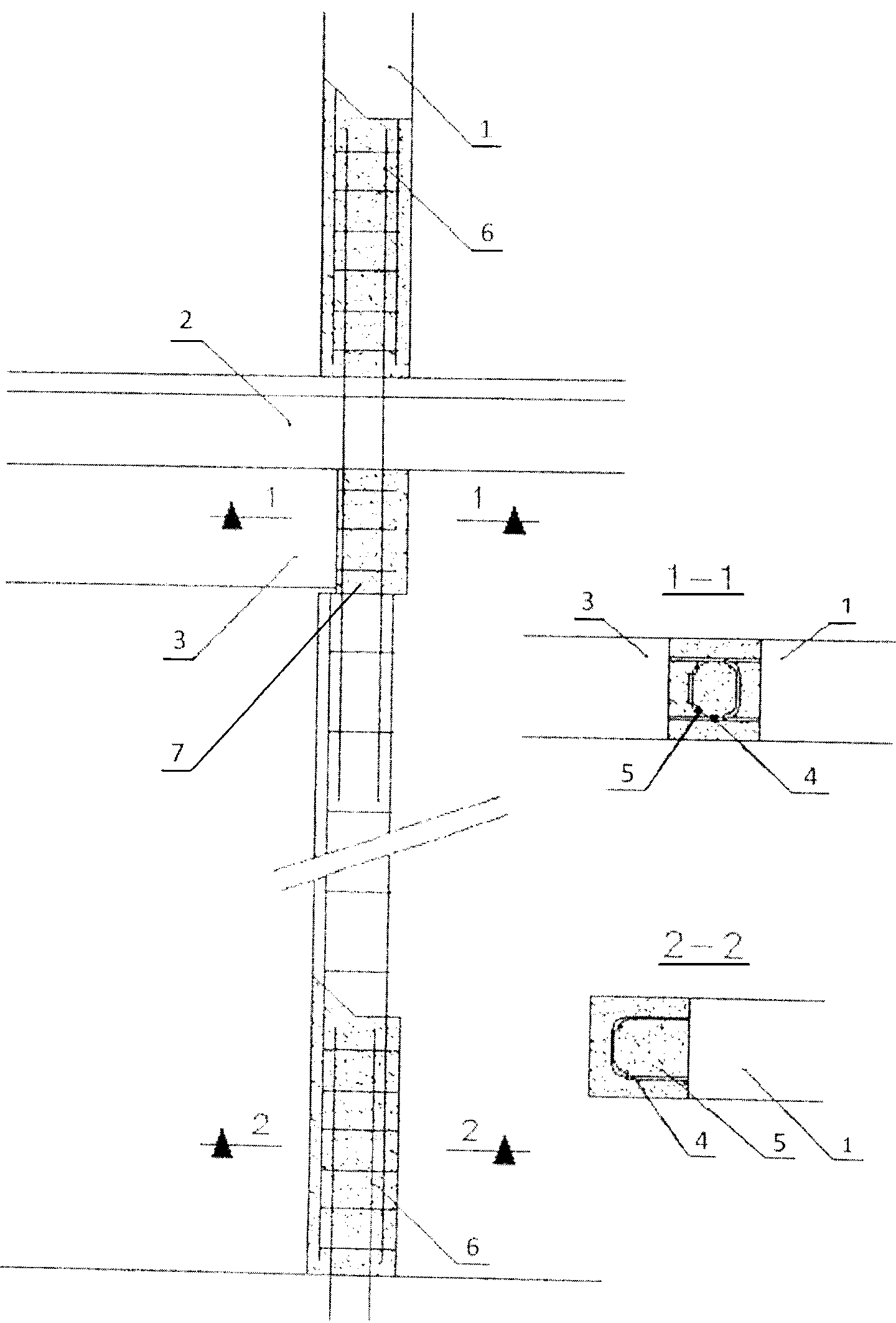
На фиг.1 - общая схема узла сопряжения со схематичными сечениями 1-1, 2-2.In Fig.1 - a General diagram of the node pair with schematic sections 1-1, 2-2.
1 - вертикальная внутренняя несущая железобетонная панель,1 - vertical inner supporting reinforced concrete panel,
2 - горизонтальная пустотная железобетонная плита перекрытия,2 - horizontal hollow reinforced concrete slab,
3 - горизонтальная несущая железобетонная балка,3 - horizontal supporting reinforced concrete beam,
4 - арматурные петлеобразные направляющие,4 - reinforcing loop-shaped guides,
5 - арматурные петлеобразные выпуски,5 - reinforcing loop-shaped releases,
6 - единый вертикальный объемный арматурный каркас,6 - a single vertical volumetric reinforcing cage,
7 - бетон.7 - concrete.
Ниже приводится пример осуществления полезной модели, никоим образом не ограничивающий все возможные варианты ее реализации.The following is an example implementation of a utility model that in no way limits all possible options for its implementation.
Вертикальные внутренние несущие железобетонные панели (1), горизонтальные несущие железобетонные балки (3) и горизонтальные пустотные железобетонные плиты перекрытий (2) изготавливают на заводе-изготовителе. Оснащение панелей (1) балок (3) и плит (2) арматурными петлеобразными направляющими (4) и выпусками (5), а также элементами единого вертикального объемного арматурного каркаса (6) осуществляют также в заводских условиях.Vertical internal supporting reinforced concrete panels (1), horizontal supporting reinforced concrete beams (3) and horizontal hollow reinforced concrete floor slabs (2) are manufactured at the factory. The panels (1) of beams (3) and plates (2) are equipped with reinforced loop-shaped guides (4) and outlets (5), as well as elements of a single vertical volumetric reinforcing cage (6) also carried out in the factory.
При изготовлении панелей (1) балок (3) и плит (2) количество арматурных направляющих (4) и выпусков (5), в том числе, предназначенных для формирования «0»-образных направляющих, учитывают изначально. При этом исходят из совокупности таких факторов как: этажность здания, географическое место его расположения (для учета зоны сейсмоустойчивости), используемый строительный материал и пр. - из расчета на необходимость сопротивления прогрессирующему разрушению конструкции, возведенной с использованием таких узлов сопряжения.In the manufacture of panels (1) of beams (3) and plates (2), the number of reinforcing rails (4) and outlets (5), including those intended to form “0” -shaped rails, are taken into account initially. At the same time, they proceed from a combination of such factors as: the number of storeys of a building, its geographical location (for taking into account the seismic stability zone), the building material used, etc., based on the need for resistance to progressive destruction of the structure constructed using such interface units.
Согласно данному примеру, количество направляющих и выпусков, в том числе, используемых для формирования «0»-образных направляющих, устанавливают исходя из соотношения: 1 (одна) петлеобразная направляющая (4) либо выпуски (5) для формирования «0»-образной направляющей на 1 м узла сопряжения. Возможны и иные соотношения.According to this example, the number of guides and outlets, including those used to form “0” -shaped guides, is set based on the ratio: 1 (one) loop-shaped guide (4) or outlets (5) to form a “0” -shaped guide on 1 m of the interface node. Other ratios are possible.
Строительные конструкции доставляют к месту возведения зданий, сооружений, чему предшествует процедура сборки узлов сопряжения строительных конструкций.Building structures are delivered to the place of construction of buildings, structures, which is preceded by the assembly procedure of the interface nodes of building structures.
В процессе сборки узла сопряжения строительных конструкций: устанавливают вертикальные внутренние несущие железобетонные панели (1), уже содержащие элементы единого вертикального объемного арматурного каркаса (6). После этого к панели (1) прикрепляются балка (3) и плита (2) с последовательностью, соответствующей конструкторской и технологической документации.In the process of assembling the interface unit of building structures: install vertical internal load-bearing reinforced concrete panels (1), already containing elements of a single vertical volumetric reinforcing cage (6). After that, a beam (3) and a plate (2) are attached to the panel (1) with the sequence corresponding to the design and technological documentation.
При соединении балки (3) и плиты (2) с панелью (1) используются арматурные выпуски (5), которыми конструктивные элементы узла сопряжения оснащаются в заводских условиях.When connecting the beam (3) and plate (2) with the panel (1), reinforcing outlets (5) are used, with which the structural elements of the interface are equipped in the factory.
В процессе сборки балку (3) и плиту (2) устанавливают торцевыми поверхностями к панели (1) с образованием между ними, по меньшей мере, двух «0»-образных направляющих из арматурных выпусков (4).During the assembly process, the beam (3) and the plate (2) are installed with end surfaces to the panel (1) with the formation between them of at least two “0” -shaped guides from the reinforcing outlets (4).
Затем все арматурные выпуски и арматурные стержни, участвующие в соединении элементов узла, соединяют дополнительным соединительным элементом, например, вязальной проволокой, образуя тем самым единый вертикальный объемный арматурный каркас узла сопряжения.Then, all the reinforcing outlets and reinforcing bars involved in connecting the elements of the node are connected by an additional connecting element, for example, a knitting wire, thereby forming a single vertical three-dimensional reinforcing frame of the interface unit.
Как видно реализацией полезной модели достигается повышение сейсмоустойчивых свойств узла сопряжения строительных конструкций, что приведет к повышению характеристик сейсмоустойчивости зданий и сооружений, возводимых с использованием данной полезной модели.As can be seen by the implementation of the utility model, an increase in the earthquake-resistant properties of the interface unit of building structures is achieved, which will lead to an increase in the seismic stability characteristics of buildings and structures constructed using this utility model.
Упрощение конструкции узла, снижение материалоемкости, и, как следствие сокращение времени, отведенного на его сборку, также являются достигаемыми при осуществлении данной полезной модели техническими результатами. Существенно повышается и долговечность зданий и сооружений, возведенных с использованием данной полезной модели.Simplification of the assembly design, reduction of material consumption, and, as a consequence, reduction of the time allotted for its assembly, are also technical results achieved by implementing this utility model. The durability of buildings and structures erected using this utility model is also significantly increased.
Claims (3)
Priority Applications (1)
| Application Number | Priority Date | Filing Date | Title |
|---|---|---|---|
| RU2011130678/03U RU110783U1 (en) | 2011-07-25 | 2011-07-25 | CONSTRUCTION CONNECTION ASSEMBLY |
Applications Claiming Priority (1)
| Application Number | Priority Date | Filing Date | Title |
|---|---|---|---|
| RU2011130678/03U RU110783U1 (en) | 2011-07-25 | 2011-07-25 | CONSTRUCTION CONNECTION ASSEMBLY |
Publications (1)
| Publication Number | Publication Date |
|---|---|
| RU110783U1 true RU110783U1 (en) | 2011-11-27 |
Family
ID=45318576
Family Applications (1)
| Application Number | Title | Priority Date | Filing Date |
|---|---|---|---|
| RU2011130678/03U RU110783U1 (en) | 2011-07-25 | 2011-07-25 | CONSTRUCTION CONNECTION ASSEMBLY |
Country Status (1)
| Country | Link |
|---|---|
| RU (1) | RU110783U1 (en) |
-
2011
- 2011-07-25 RU RU2011130678/03U patent/RU110783U1/en not_active IP Right Cessation
Similar Documents
| Publication | Publication Date | Title |
|---|---|---|
| TWI241374B (en) | Constructing the large-span self-braced buildings of composite load-bearing wall-panels and floors | |
| RU80487U1 (en) | SYSTEM precast frame housing (ACS) AND COUPLING NODE trough ribbed plate overlap with monolithic prefabricated beams, floors, INTERFACE UNIT PREFABRICATED CONCRETE COLUMN, National COUPLING NODE-MONOLITHIC crossbars CO precast concrete columns and trough ribbed plate SLABS | |
| RU111161U1 (en) | CONSTRUCTION CONNECTION ASSEMBLY | |
| RU110776U1 (en) | CONSTRUCTION CONNECTION ASSEMBLY | |
| RU111159U1 (en) | CONSTRUCTION CONNECTION ASSEMBLY | |
| RU110777U1 (en) | CONSTRUCTION CONNECTION ASSEMBLY | |
| RU110784U1 (en) | CONSTRUCTION CONNECTION ASSEMBLY | |
| RU84881U1 (en) | FRAME OF BUILDINGS AND STRUCTURES | |
| RU110783U1 (en) | CONSTRUCTION CONNECTION ASSEMBLY | |
| RU110780U1 (en) | CONSTRUCTION CONNECTION ASSEMBLY | |
| RU60099U1 (en) | MILITARY MONOLITHIC REINFORCED CONCRETE FRAME OF MULTI-STOREY BUILDING | |
| WO2013187803A2 (en) | Method for increasing the load-bearing capacity of a girderless monolithic reinforced-concrete framework | |
| RU111158U1 (en) | CONSTRUCTION CONNECTION ASSEMBLY | |
| RU110782U1 (en) | CONSTRUCTION CONNECTION ASSEMBLY | |
| RU111167U1 (en) | CONSTRUCTION CONNECTION ASSEMBLY | |
| RU111166U1 (en) | CONSTRUCTION CONNECTION ASSEMBLY | |
| RU110779U1 (en) | CONSTRUCTION CONNECTION ASSEMBLY | |
| RU110778U1 (en) | CONSTRUCTION CONNECTION ASSEMBLY | |
| RU111156U1 (en) | CONSTRUCTION CONNECTION ASSEMBLY | |
| RU111553U1 (en) | CONSTRUCTION CONNECTION ASSEMBLY | |
| RU110775U1 (en) | CONSTRUCTION CONNECTION ASSEMBLY | |
| RU111164U1 (en) | CONSTRUCTION CONNECTION ASSEMBLY | |
| RU111160U1 (en) | CONSTRUCTION CONNECTION ASSEMBLY | |
| RU111863U1 (en) | CONSTRUCTION CONNECTION ASSEMBLY | |
| RU111554U1 (en) | CONSTRUCTION CONNECTION ASSEMBLY |
Legal Events
| Date | Code | Title | Description |
|---|---|---|---|
| MM9K | Utility model has become invalid (non-payment of fees) |
Effective date: 20180726 |