NL9101394A - METHOD AND APPARATUS FOR DETERMINING THE HEIGHT OF A TARGET - Google Patents
METHOD AND APPARATUS FOR DETERMINING THE HEIGHT OF A TARGET Download PDFInfo
- Publication number
- NL9101394A NL9101394A NL9101394A NL9101394A NL9101394A NL 9101394 A NL9101394 A NL 9101394A NL 9101394 A NL9101394 A NL 9101394A NL 9101394 A NL9101394 A NL 9101394A NL 9101394 A NL9101394 A NL 9101394A
- Authority
- NL
- Netherlands
- Prior art keywords
- target
- antenna
- earth
- receiving
- height
- Prior art date
Links
Classifications
-
- G—PHYSICS
- G01—MEASURING; TESTING
- G01S—RADIO DIRECTION-FINDING; RADIO NAVIGATION; DETERMINING DISTANCE OR VELOCITY BY USE OF RADIO WAVES; LOCATING OR PRESENCE-DETECTING BY USE OF THE REFLECTION OR RERADIATION OF RADIO WAVES; ANALOGOUS ARRANGEMENTS USING OTHER WAVES
- G01S13/00—Systems using the reflection or reradiation of radio waves, e.g. radar systems; Analogous systems using reflection or reradiation of waves whose nature or wavelength is irrelevant or unspecified
- G01S13/02—Systems using reflection of radio waves, e.g. primary radar systems; Analogous systems
- G01S13/06—Systems determining position data of a target
- G01S13/42—Simultaneous measurement of distance and other co-ordinates
- G01S13/44—Monopulse radar, i.e. simultaneous lobing
- G01S13/4418—Monopulse radar, i.e. simultaneous lobing with means for eliminating radar-dependent errors in angle measurements, e.g. multipath effects
Landscapes
- Engineering & Computer Science (AREA)
- Radar, Positioning & Navigation (AREA)
- Remote Sensing (AREA)
- Computer Networks & Wireless Communication (AREA)
- Physics & Mathematics (AREA)
- General Physics & Mathematics (AREA)
- Radar Systems Or Details Thereof (AREA)
- Length Measuring Devices With Unspecified Measuring Means (AREA)
Description
Werkwijze en inrichting voor het bepalen van de hoogte van een doel.Method and device for determining the height of a target.
De uitvinding heeft betrekking op een werkwijze voor het met behulp van een radarapparaat bepalen van.de hoogte van een zich laag boven het aardoppervlak bevindende doel waarbij het radarapparaat is voorzien van een zend- en ontvangeenheid, een met de zend- en ontvangeenheid verbonden zend- en ontvang antenne en een met de zenden ontvangeenheid verbonden signaalverwerkingseenheid, waarbij : - het doel wordt aangestraald met door de zendeenheid en zendantenne uitgezonden electromagnetische straling; - het uitgezonden signaal rechtstreeks via het doel en indirect via het doel en het aardoppervlak in de richting van de ontvangantenne wordt gereflecteerd; - met behulp van de ontvangeenheid, uit de met behulp van de ontvangantenne ontvangen signalen, complexe somsignalen Σ en complexe elevatieverschilsignalen Δ worden bepaald; - met behulp van de signaalverwerkingseenheid een algorithme wordt uitgevoerd voor het uit de complexe som- en elevatieverschilsignalen bepalen van de hoogte van het doel.The invention relates to a method for determining the height of a target located low above the surface of the earth with the aid of a radar device, wherein the radar device is provided with a transmitting and receiving unit, a transmitting unit connected to the transmitting and receiving unit. and receiving antenna and a signal processing unit connected to the transmitting receiving unit, wherein: - the target is irradiated with electromagnetic radiation emitted by the transmitting unit and transmitting antenna; - the transmitted signal is reflected directly through the target and indirectly through the target and the earth's surface towards the receiving antenna; - with the aid of the receiver unit, complex sum signals Σ and complex elevation difference signals Δ are determined from the signals received with the aid of the receiving antenna; - an algorithm is performed with the aid of the signal processing unit for determining the height of the target from the complex sum and elevation difference signals.
De uitvinding heeft tevens betrekking op een inrichting voor het bepalen van de hoogte van een laag boven het aardoppervlak bevindend doel, omvattende een radarapparaat voorzien van een zend inrichting met een daarop aangesloten zendantenne, een ontvangantenne met een daarop aangesloten ontvangketen, waarbij het doel wordt aangestraald met door de zendinrichting en de zendantenne uitgezonden electromagnetische straling en het uitgezonden signaal rechtstreeks door het doel en door het doel via het aardoppervlak wordt gereflecteerd in de richting van de ontvangantenne en waarbij met de ontvangketen voor het doel complexe somsignalen Σ en tenminste complexe elevatieverschilsignalen Δ kunnen worden gegenereerd, een op de ontvangketen aangesloten signaalprocessor voorzien van een algorithme voor het bepalen van de hoogte van het doel ht, en op de signaalprocessor aangesloten middelen voor het richten van de zendantenne en de ontvangantenne op een richtpunt.The invention also relates to a device for determining the height of a target located above the earth's surface, comprising a radar device comprising a transmitting device with a transmitting antenna connected thereto, a receiving antenna with a receiving chain connected thereto, the target being irradiated with electromagnetic radiation emitted by the transmitter and transmitter antenna and the emitted signal being reflected directly from the target and by the target through the surface of the earth towards the receiving antenna and whereby the receiving chain for the target allows complex sum signals Σ and at least complex elevation difference signals Δ are generated, a signal processor connected to the receiving circuit provided with an algorithm for determining the height of the target ht, and means connected to the signal processor for pointing the transmitting antenna and the receiving antenna at a target point.
De hoogte van een doel kan worden bepaald met behulp van een monopuls radarapparaat. Dit principe is bijvoorbeeld beschreven in het boek "Introduction to Radar Systems", tweede editie, pag. 160-190, van M.L. Skolnik. Een probleem dat zich voordoet bij de bepaling van de hoogte van een doel dat op geringe hoogte boven het zeeoppervlak, en in mindere mate ook het landoppervlak, vliegt, is beschreven op pag. 172-176. De oorzaak van het probleem is gelegen in het feit dat het radarapparaat niet alleen echo's van het doel, maar ook gespiegeld door het zeeoppervlak echo's van dit doel ontvangt. Zonder dit spiegeleffect is de hoogte van het doel eenvoudig te bepalen uit door het monopuls radarapparaat afgegeven waarden van de doelsafstand R en van de elevatiefoutspanning E(0). Met het spiegeleffect krijgt de elevatiefoutspanning een complexe waarde en is een nauwkeurige bepaling van de doelshoogte niet langer mogelijk.The height of a target can be determined using a monopulse radar device. This principle is described, for example, in the book "Introduction to Radar Systems", second edition, p. 160-190, from M.L. Skolnik. A problem that arises in determining the height of a target flying at a low height above the sea surface, and to a lesser extent also the land surface, is described on p. 172-176. The cause of the problem lies in the fact that the radar device not only receives echoes from the target, but also echoes from the target mirrored by the sea surface. Without this mirror effect, the height of the target can be easily determined from values of the target distance R and the elevation error voltage E (0) delivered by the monopulse radar device. With the mirror effect, the elevation error voltage acquires a complex value and an accurate determination of the target height is no longer possible.
De enige manier om genoemd spiegeleffect te voorkomen is het toepassen van een radarbundel die zo nauw is dat wel echo's van het doel maar geen echo's gespiegeld via het zeeoppervlak worden ontvangen. Het nadeel is echter dat met een zo nauwe bundel het doel zeer moeilijk te vinden is. Het octrooi US-A 4,743,907 beschrijft een zeer elegante wijze om dit nadeel op te heffen. Door twee monopuls radarapparaten volledig te integreren, waarbij het eerste radarapparaat een relatief grote golflengte en daarmee een wijde bundel heeft, het tweede radarapparaat een relatief kleine golflengte en daarmee een nauwe bundel heeft, kan zowel in de acquisitiefase als ook in de volgfase een optimale performance worden verkregen. De kosten van een dergelijk systeem zijn echter relatief hoog.The only way to prevent said mirror effect is to use a radar beam so narrow that echoes from the target but no echoes are mirrored from the sea surface. The drawback, however, is that with such a narrow beam, the target is very difficult to find. The patent US-A 4,743,907 describes a very elegant way of removing this drawback. By fully integrating two monopulse radar devices, where the first radar device has a relatively large wavelength and therefore a wide beam, the second radar device has a relatively small wavelength and therefore a narrow beam, optimal performance can be achieved both in the acquisition phase and in the tracking phase. be obtained. However, the costs of such a system are relatively high.
Een methode om de doelshoogte nauwkeurig te bepalen, ondanks het optreden van een spiegeleffect, is beschreven in het octrooi US-A 4,796,031. Volgens de daar beschreven methode wordt de radarantenne niet op het doel, maar precies tussen het doel en zijn spiegelbeeld gericht. Door nu met tenminste twee verschillende radargolflengten, die in een vooraf bepaalde verhouding tot elkaar staan, te meten, kan een stelsel van vergelijkingen worden opgelost waaruit een aantal mogelijke doelshoogten volgen. Door achtereenvolgens op deze wijze bepaalde mogelijke doelshoogten met elkaar te vergelijken, kan / de doelshoogte worden gevonden.A method of accurately determining the target height, despite the occurrence of a mirror effect, is described in US-A 4,796,031. According to the method described there, the radar antenna is not aimed at the target, but precisely between the target and its mirror image. By now measuring with at least two different radar wavelengths, which are in a predetermined relationship to each other, a system of equations can be solved from which a number of possible target heights follow. By successively comparing certain possible target heights in this way, the target height can be found.
Een alternatieve methode om de doelshoogte nauwkeurig te bepalen is beschreven in het octrooi EP-B 0.087.355. Volgens deze methode wordt de antenne-oriëntatie voortdurend gevarieerd. Met meetwaarden, verkregen bij verschillende antenne-oriëntaties kunnen weer stelsels van vergelijkingen worden opgelost die de doelshoogte opleveren.An alternative method for accurately determining the target height is described in patent EP-B 0.087.355. According to this method, the antenna orientation is constantly varied. Measurements obtained at different antenna orientations can again solve systems of equations that yield the target height.
Beide methoden zijn omslachtig en hebben als nadeel dat het monopuls radarapparaat op een richtpunt is gericht dat niet samenvalt met het doel. Dit niet op het doel gericht zijn is voor een monopuls radarapparaat een vanzelfsprekend suboptimale conditie, die echter volgens de stand der techniek nodig is om een oplosbaar stelsel van vergelijkingen te verkrijgen.Both methods are cumbersome and have the drawback that the monopulse radar device is aimed at a target that does not coincide with the target. This non-targeting is, of course, a sub-optimal condition for a monopulse radar apparatus, but it is necessary in the prior art to obtain a soluble system of equations.
De hoogte van een doel kan volgens de uitvinding worden bepaald met een werkwijze die als kenmerk heeft de zend- en ontvangantenne althans nagenoeg op het doel worden gericht.The height of a target can be determined according to the invention by a method which is characterized in that the transmitting and receiving antenna are directed at least substantially at the target.
Daarnaast is de beschreven werkwijze eenvoudig, ze heeft als kenmerk dat de hoogte van het doel wordt bepaald door het oplossen van de vergelijking:In addition, the described method is simple, it is characterized that the height of the target is determined by solving the equation:

De inrichting volgens de uitvinding heeft als kenmerk, dat het doel en het richtpunt althans nagenoeg samenvallen.The device according to the invention is characterized in that the target and the target point coincide at least substantially.
De uitvinding zal nu nader aan de hand van bijgaande figuren worden toegelicht, waarvan:The invention will now be further elucidated with reference to the annexed figures, of which:
Fig. 1 een schematisch diagram van een mogelijke uitvoeringsvorm van een monopuls radarapparaat volgens de uitvinding weergeeft; Fig. 2 een mogelijke elevatiefoutspanningscurve weergeeft;Fig. 1 shows a schematic diagram of a possible embodiment of a monopulse radar device according to the invention; Fig. 2 depicts a possible elevation error voltage curve;
Fig. 3 het spiegeleffect illustreert.Fig. 3 illustrates the mirror effect.
Voor het nauwkeurig bepalen van de hoogte van een laag over het zeeoppervlak of aardoppervlak vliegend doel gaan we uit van een monopuls radarapparaat. In deze situatie zullen door het radarapparaat afgegeven somsignalen en elevatieverschilsignalen complexe waarden krijgen, die door een op het radarapparaat aangesloten signaalprocessor dienen te worden verwerkt.To accurately determine the height of a layer flying over the sea surface or earth's surface, we use a monopulse radar device. In this situation, sum signals and elevation difference signals output from the radar device will acquire complex values to be processed by a signal processor connected to the radar device.
Fig. 1 geeft een schematisch diagram van een mogelijke uitvoeringsvorm van een monopuls radarapparaat volgens de uitvinding.Fig. 1 is a schematic diagram of a possible embodiment of a monopulse radar apparatus according to the invention.
Om de beschrijving niet nodeloos gecompliceerd te maken, wordt alleen het monopuls gedrag in elevatie in de analyse betrokken.In order not to make the description unnecessarily complicated, only the monopulse behavior in elevation is included in the analysis.
Twee boven elkaar geplaatste antenne-elementen 1, 2 zijn aangesloten op een in het vakgebied bekende koppelaar 3, die hieruit een somkanaal 4 en een verschilkanaal 5 vormt. Op het somkanaal 4 is via een TR-schakelaar 6 een zender 7 aangesloten, die wordt gestuurd vanuit een frequentie- en timingeenheid 8 en bijvoorbeeld puls-vormige signalen uitzendt. Via het somkanaal ontvangen signalen worden via TR-schakelaar 6 naar een mengtrap 9 gevoerd, die een LO signaal van de frequentie- en timingeenheid 8 ontvangt. Het zo gevormde middenfrequent somsignaal wordt versterkt in midden-frequentversterker 10 en omgezet in een digitaal, complex somsignaal Σ door A/D converter en Hilbert filter 11. Via het verschilkanaal 5 ontvangen signalen worden naar een mengtrap 12 gevoerd, die eveneens een LO signaal van de frequentie- en timingeenheid 8 ontvangt. Het zo gevormde middenfrequent verschilsignaal wordt versterkt in middenfrequentversterker 13 en omgezet in een digitaal, complex verschilsignaal Δ door A/D converter en Hilbert filter 14. Beide signalen worden toegevoerd aan een signaalprocessor 15, die hieruit een elevatiefoutspanning S = Δ/Σ bepaalt. Het is mogelijk A/D converter en Hilbert filter 11, 14 te vervangen door fasegevoelige quadratuurdetectoren plus A/D converters, maar de hier gegeven realisatie voldoet beter t.a.v. gain en offset stabiliteit.Two antenna elements 1, 2 placed one above the other are connected to a coupler 3 known in the art, which forms a sum channel 4 and a difference channel 5 therefrom. A transmitter 7 is connected to the sum channel 4 via a TR switch 6, which is controlled from a frequency and timing unit 8 and transmits, for example, pulse-shaped signals. Signals received via the sum channel are fed via TR switch 6 to a mixer 9, which receives an LO signal from the frequency and timing unit 8. The medium-frequency sum signal thus formed is amplified in medium-frequency amplifier 10 and converted into a digital complex sum signal Σ by A / D converter and Hilbert filter 11. Signals received via difference channel 5 are fed to a mixer 12, which also has an LO signal of the frequency and timing unit 8 receives. The intermediate frequency difference signal thus formed is amplified in intermediate frequency amplifier 13 and converted into a digital, complex difference signal Δ by A / D converter and Hilbert filter 14. Both signals are applied to a signal processor 15, which determines an elevation error voltage S = Δ / Σ. It is possible to replace A / D converter and Hilbert filter 11, 14 with phase-sensitive quadrature detectors plus A / D converters, but the realization given here is better with regard to gain and offset stability.
}}
Wanneer er sprake is van één stilstaand doel in de bundel, dan zullen de vectoren Σ en Δ steeds voor elke uitgezonden puls gelijk zijn en onderling een vaste hoek hebben. Voor één bewegend doel in de bundel zullen beide vectoren roteren met de dopplerfrequentie, maar ze behouden dezelfde vaste hoek. Het is gebruikelijk om in één van beide kanalen een fase-afregelpunt aan te brengen, zodanig dat beide vectoren in eikaars verlengde liggen. Voor één doel is de elevatiefoutspanning dan reëel. De reële elevatiefoutspanningscurve E(0) is weergegeven in Fig. 2. Opgemerkt wordt dat de elevatiefoutspanning, ondanks de naam, dimensieloos is. Voor zover dit van belang is, kan E(0), althans voor kleine waarden van Θ, worden gelineariseerd in de signaalprocessor 15, bijvoorbeeld door het raadplegen van een lineariseringstabel. Dan geldt voor kleine hoeken θ’. E(0) = Κ.Θ. Verder kan signaalprocessor 15 een AGC stuursignaal genereren waarmee de versterking van beide middenfrequentversterkers 10, 13 zodanig wordt geregeld, dat de amplitude van het echosignaal van het doel in het somsignaal Σ nagenoeg constant wordt gehouden. Dit vermindert de fasegelijkloop-eisen voor het som- en verschilkanaal, maakt het mogelijk A/D converters met een beperkt dynamisch bereik te benutten en beperkt de omvang van de lineariseringstabel.If there is one stationary target in the beam, the vectors Σ and Δ will always be equal for each transmitted pulse and have a fixed angle. For one moving target in the beam, both vectors will rotate at the Doppler frequency, but retain the same fixed angle. It is customary to provide a phase adjustment point in one of the channels, such that both vectors are in line with each other. The elevation error voltage is then real for one purpose. The real elevation error voltage curve E (0) is shown in Fig. 2. It should be noted that the elevation error voltage, despite the name, is dimensionless. Where relevant, E (0), at least for small values of Θ, can be linearized in the signal processor 15, for example, by consulting a linearization table. Then applies to small angles θ ’. E (0) = Κ.Θ. Furthermore, signal processor 15 can generate an AGC control signal with which the amplification of both medium frequency amplifiers 10, 13 is controlled such that the amplitude of the target's echo signal in the sum signal Σ is kept almost constant. This reduces phase synchronization requirements for the sum and difference channels, allows use of A / D converters with a limited dynamic range, and limits the size of the linearization table.
In het algemeen zal de signaalprocessor 15 nog enkele andere, voor de hier beschreven uitvinding minder belangrijke functies vervullen. Zo zal in de signaalprocessor 15 bijvoorbeeld een in het vakgebied welbekende tijdpoortfunctie worden gerealiseerd. Tevens zal een vorm van MTI of MTD doppler processing op de door de A/D converters enIn general, the signal processor 15 will perform some other functions, which are less important for the invention described here. For example, a time gate function well known in the art will be realized in the signal processor 15. It will also do some form of MTI or MTD doppler processing on the A / D converters and
Hilbert filters 11, 14 afgegeven waarden worden toegepast. Daarnaast zal de signaalprocessor 15 stuursignalen genereren waarmee de zendantenne en de ontvangantenne worden gericht.Hilbert filters 11, 14 output values are used. In addition, the signal processor 15 will generate control signals targeting the transmit antenna and the receive antenna.
Wanneer er sprake is van één doel in de bundel, waarvan een echo direct en gespiegeld via het zeeoppervlak wordt ontvangen, zoals weergegeven in Fig. 3, dan blijkt S een complexe waarde te krijgen. In Fig. 3 is ha de hoogte van de antenne boven het zeeoppervlak, ht de hoogte van het doel boven het zeeoppervlak, R de afstand van het doel tot de radarantenne en 9Q de elevatiehoek van de antenne.When there is one target in the beam, an echo is received directly and mirrored from the sea surface, as shown in Fig. 3, then S appears to have a complex value. In FIG. 3 is ha the height of the antenna above the sea surface, ht the height of the target above the sea surface, R the distance from the target to the radar antenna and 9Q the angle of elevation of the antenna.
Voor een bewegend doel wordt S een functie van de doelsafstand R, de doelshoogte hfc, de radarzendergolflengte λ en van enkele systeemconstanten. Ons doel is het vinden van een vergelijking die deze waarden bevat en waaruit ht opgelost kan worden. Deze vergelijking vormt dan de basis voor de geclaimde werkwijze en inrichting.For a moving target, S becomes a function of the target distance R, the target height hfc, the radar transmitter wavelength λ, and some system constants. Our goal is to find an equation that contains these values and from which ht can be solved. This comparison then forms the basis for the claimed method and device.
Voor het opstellen van de vergelijking worden de volgende grootheden gedefinieerd: h& hoogte van de antenne boven het zeeoppervlak. hfc hoogte van het doel boven het zeeoppervlak.For comparing the equation, the following parameters are defined: h & height of the antenna above the sea surface. hf height of the target above the sea surface.
R afstand van het doel tot de radarantenne.R distance from the target to the radar antenna.
9 elevatiehoek van de antenne.9 elevation angle of the antenna.
elevatiefouthoek van het doel.elevation error angle of the target.
9m elevatiefouthoek van het spiegelbeeld. p reflectiecoefficient van het zeeoppervlak.9m elevation error angle of the mirror image. p reflection coefficient of the sea surface.
Φ storingsfaseterm voor de reflectie op het zeeoppervlak φ faseverschil tussen de reflecties van doel en spiegelbeeld.Φ disturbance phase term for the reflection on the sea surface φ phase difference between the reflections of target and mirror image.
G^,(0) antennediagram van het elevatiesomkanaal.G ^, (0) antenna diagram of the elevation sum channel.
G^(0) antennediagram van het elevatieverschilkanaal.G ^ (0) antenna diagram of the elevation difference channel.
E(0) elevatiefoutspanningscurve.E (0) elevation error voltage curve.
Hieruit kunnen op elementaire wijze de volgende benaderingen worden afgeleid:The following approaches can be derived in an elementary manner:

(1)(1)

(2)(2)

\ (3)\ (3)
Verder geldt:Furthermore, the following applies:

(4)(4)

(5)(5)

(6)(6)

(7)(7)
We definiëren:We define:

(8)(8)

(9)(9)
Bij de laatste vergelijking is gebruik gemaakt van het feit dat E(0) antisymmetrisch is.The latter comparison took advantage of the fact that E (0) is anti-symmetric.
We definiëren een gecorrigeerde reflectiecoëfficient G, waarbij we rekening houden met het feit dat bij een op het doel gerichte monopuls antenne, de reflectie van het spiegelbeeld extra wordt verzwakt door het antennediagram:We define a corrected reflection coefficient G, taking into account that with a target monopulse antenna, the reflection of the mirror image is additionally weakened by the antenna diagram:

(10)(10)
Dan volgt uit (3), (7), (8), (9) en (10):Then it follows from (3), (7), (8), (9) and (10):

(11)(11)
In een normale doelvolgsituatie geldt dat de antenne op het doel is gericht, dus A = 0:In a normal target tracking situation, the antenna is aimed at the target, so A = 0:

(12)(12)
Voor het reële deel van S geldt:For the real part of S holds:
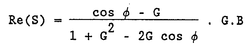
(13)(13)
Voor het argument van S geldt:For the argument of S holds:

(14) dus:(14) so:

(15)(15)
Combineren we (13) en (15), dan levert dit de gezochte vergelijking:If we combine (13) and (15), this yields the searched equation:

(16)(16)
Bij inspectie blijkt (16) naast enkele systeemparameters en enkele meetwaarden als enige onbekenden hfc en Φ te bevatten.Inspection shows (16) that besides some system parameters and some measured values, only unknowns contain hfc and Φ.
Voor een glad zeeoppervlak mogen we veronderstellen datFor a smooth sea surface we can assume that

(17)(17)
Dit levert samen met (16)This yields together with (16)

(18)(18)
Veronderstellen we dat E(0) lineair is voor kleine (9), dan is dit een vierkantsvergelijking in ht· Is E(9) niet lineair, dan kan de vergelijking worden opgelost met een op de methode van Newton gebaseerde oplossingswijze. Op de zo in de tijd verkregen reeks van schattingen van de doelshoogte kan dan, zoals gebruikelijk in het vakgebied, in een filterproces met een zekere tijdconstante en met een voorziening voor het verwijderen van sterk afwijkende schattingen, een schatter worden verkregen voor de doelshoogte.Supposing that E (0) is linear for small (9), then this is a square equation in ht. If E (9) is not linear, the equation can be solved with a Newton-based solution. From the series of target height estimates thus obtained over time, an estimate for the target height can then be obtained, as is customary in the art, in a filtering process with a certain time constant and with a provision for the removal of strongly deviating estimates.
Een tweede oplossingsmethodiek dient te worden gekozen als de veronderstelling van een glad zeeoppervlak niet geldt, dus alsA second solution method should be chosen if the assumption of a smooth sea surface does not apply, ie if

We kunnen dan de onbekende Φ elimineren door bij twee verschillende golflengten te meten. Uit (16) leiden we af:We can then eliminate the unknown Φ by measuring at two different wavelengths. From (16) we derive:

(19)(19)
Voor kleine golflengteverschillen passen we de volgende benadering toe:For small wavelength differences we apply the following approach:

(20)(20)
Met (3), (9) en (19) geeft dit:With (3), (9) and (19) this gives:

(21)(21)
Deze vergelijking kan op één van de bij (18) beschreven wijzen worden opgelost.This equation can be solved in one of the ways described at (18).
De op één van bovenstaande wijzen verkregen waarden van ht kunnen worden gebruikt voor het richten van de zendantenne en de ontvang-antenne op het doel. Hiermee wordt een elevatiefouthoek gerealiseerd die, in vergelijking met een monopuls radarapparaat waarbij het imaginaire deel van de elevatiefoutspanning wordt verwaarloosd, een orde van grootte kan verbeteren. Daarnaast is de werkwijze relatief ongevoelig voor verstoringen, in het bijzonder de voorwaarde A = 0 blijkt niet stringent te zijn.The values of ht obtained in any of the above can be used to direct the transmit antenna and receive antenna at the target. This achieves an elevation error angle which, compared to a monopulse radar apparatus in which the imaginary part of the elevation error voltage is neglected, can improve by an order of magnitude. In addition, the method is relatively insensitive to disturbances, in particular the condition A = 0 appears not to be stringent.
Claims (9)


Priority Applications (15)
| Application Number | Priority Date | Filing Date | Title |
|---|---|---|---|
| NL9101394A NL9101394A (en) | 1991-08-16 | 1991-08-16 | METHOD AND APPARATUS FOR DETERMINING THE HEIGHT OF A TARGET |
| DE69222499T DE69222499T2 (en) | 1991-08-16 | 1992-07-21 | Method and device for determining the height of a target |
| ES92202228T ES2108081T3 (en) | 1991-08-16 | 1992-07-21 | METHOD AND APPARATUS FOR DETERMINING THE HEIGHT OF A TARGET. |
| EP92202228A EP0533223B1 (en) | 1991-08-16 | 1992-07-21 | Method and apparatus for the determination of the height of a target |
| CA002074411A CA2074411C (en) | 1991-08-16 | 1992-07-22 | Target height determination system using directly and indirectly reflected signals |
| ZA925524A ZA925524B (en) | 1991-08-16 | 1992-07-22 | Method and apparatus for the determination of the height of a target |
| US07/922,785 US5278564A (en) | 1991-08-16 | 1992-07-31 | Method and apparatus for the determination of the height of a target |
| AU20797/92A AU653047B2 (en) | 1991-08-16 | 1992-08-05 | Method and apparatus for the determination of the height of a target |
| KR1019920014401A KR100214345B1 (en) | 1991-08-16 | 1992-08-11 | Low altitude target decision method and device |
| BR929203123A BR9203123A (en) | 1991-08-16 | 1992-08-13 | PROCESS AND APPARATUS FOR DETERMINING, THROUGH A RADAR APPARATUS, FROM THE HEIGHT OF A TARGET TO LOW LIFTING, AND, SIGNAL PROCESSOR |
| JP4216117A JPH05196725A (en) | 1991-08-16 | 1992-08-13 | Apparatus and method for judging height of low-elevation target |
| NO923161A NO300398B1 (en) | 1991-08-16 | 1992-08-13 | Method and apparatus for determining the height of a target |
| TR00807/92A TR27024A (en) | 1991-08-16 | 1992-08-14 | A method and device for determining the height of a target. |
| CN 92109463 CN1069808A (en) | 1991-08-16 | 1992-08-15 | Determine the method and apparatus of object height |
| GR970403359T GR3025708T3 (en) | 1991-08-16 | 1997-12-17 | Method and apparatus for the determination of the height of a target |
Applications Claiming Priority (2)
| Application Number | Priority Date | Filing Date | Title |
|---|---|---|---|
| NL9101394 | 1991-08-16 | ||
| NL9101394A NL9101394A (en) | 1991-08-16 | 1991-08-16 | METHOD AND APPARATUS FOR DETERMINING THE HEIGHT OF A TARGET |
Publications (1)
| Publication Number | Publication Date |
|---|---|
| NL9101394A true NL9101394A (en) | 1993-03-16 |
Family
ID=19859618
Family Applications (1)
| Application Number | Title | Priority Date | Filing Date |
|---|---|---|---|
| NL9101394A NL9101394A (en) | 1991-08-16 | 1991-08-16 | METHOD AND APPARATUS FOR DETERMINING THE HEIGHT OF A TARGET |
Country Status (15)
| Country | Link |
|---|---|
| US (1) | US5278564A (en) |
| EP (1) | EP0533223B1 (en) |
| JP (1) | JPH05196725A (en) |
| KR (1) | KR100214345B1 (en) |
| CN (1) | CN1069808A (en) |
| AU (1) | AU653047B2 (en) |
| BR (1) | BR9203123A (en) |
| CA (1) | CA2074411C (en) |
| DE (1) | DE69222499T2 (en) |
| ES (1) | ES2108081T3 (en) |
| GR (1) | GR3025708T3 (en) |
| NL (1) | NL9101394A (en) |
| NO (1) | NO300398B1 (en) |
| TR (1) | TR27024A (en) |
| ZA (1) | ZA925524B (en) |
Families Citing this family (20)
| Publication number | Priority date | Publication date | Assignee | Title |
|---|---|---|---|---|
| JP3860607B2 (en) * | 1994-09-14 | 2006-12-20 | コーニンクレッカ フィリップス エレクトロニクス エヌ ヴィ | Wireless transmission system and wireless device used therefor |
| US6741202B1 (en) * | 2003-04-29 | 2004-05-25 | Kapriel V. Krikorian | Techniques for 3-dimensional synthetic aperture radar |
| US7265710B2 (en) * | 2004-11-12 | 2007-09-04 | Northrop Grumman Corporation | Multipath height finding method |
| WO2006086605A2 (en) * | 2005-02-10 | 2006-08-17 | Automotive Systems Laboratory, Inc. | Automotive radar system with guard beam |
| US7940206B2 (en) | 2005-04-20 | 2011-05-10 | Accipiter Radar Technologies Inc. | Low-cost, high-performance radar networks |
| FR2901613B1 (en) * | 2006-05-16 | 2009-12-11 | Thales Sa | METHOD FOR DETERMINING THE POSITION, ESPECIALLY IN ELEVATION, OF A FLYING TARGET WITH A VERY LOW ALTITUDE |
| US7808426B1 (en) * | 2008-05-05 | 2010-10-05 | The United States Of America As Represented By The Secretary Of The Navy | Remote sensing of wave heights using a broadband radar arrangement |
| US7830302B1 (en) * | 2008-05-05 | 2010-11-09 | The United States Of America As Represented By The Secretary Of The Navy | Remote sensing of wave heights using a narrowband radar arrangement |
| ES2636996T3 (en) * | 2008-12-17 | 2017-10-10 | Thales Nederland B.V. | Apparatus for estimating the height at which a target flies above a reflective surface |
| JP4905512B2 (en) * | 2009-07-09 | 2012-03-28 | 株式会社デンソー | Target information estimation device |
| CN102012505B (en) * | 2010-10-15 | 2012-12-05 | 西安电子科技大学 | Method for estimating direction of arrival of radar low-elevation target |
| CA3079864C (en) | 2011-09-09 | 2022-06-21 | Accipiter Radar Technologies, Inc. | Device and method for 3d sampling with avian radar |
| US8988230B2 (en) | 2011-10-25 | 2015-03-24 | Accipiter Radar Technologies Inc. | Device and method for smart, non-habituating, automatic bird deterrent system |
| DE102011056861A1 (en) * | 2011-12-22 | 2013-06-27 | Jenoptik Robot Gmbh | Method and arrangement for acquiring measured data of a vehicle in a radar field |
| EP2614851B1 (en) | 2012-01-16 | 2019-08-07 | Michael Tchirikov | Catheter |
| US9625720B2 (en) | 2012-01-24 | 2017-04-18 | Accipiter Radar Technologies Inc. | Personal electronic target vision system, device and method |
| JP6044116B2 (en) * | 2012-05-23 | 2016-12-14 | 日本電気株式会社 | Radar apparatus, angle measuring method and program |
| US8860602B2 (en) | 2012-10-09 | 2014-10-14 | Accipiter Radar Technologies Inc. | Device and method for cognitive radar information network |
| CN103713286B (en) * | 2014-01-08 | 2016-03-09 | 陕西长岭电子科技有限责任公司 | There is the high-resolution radio altimeter of positioning function and the method for measuring position |
| EP3588135B1 (en) | 2018-06-28 | 2021-05-05 | Aptiv Technologies Limited | Method of determining an alignment error of an antenna and vehicle with an antenna and a detection device |
Family Cites Families (4)
| Publication number | Priority date | Publication date | Assignee | Title |
|---|---|---|---|---|
| CH592887A5 (en) * | 1975-05-22 | 1977-11-15 | Siemens Ag Albis | |
| FR2377043A1 (en) * | 1977-01-07 | 1978-08-04 | Thomson Csf | METHOD OF MEASURING THE ALTITUDE OF A TARGET MOVING AT A VERY LOW SITE AND TRACKING RADAR IMPLEMENTING THIS PROCEDURE |
| FR2408843A1 (en) * | 1977-11-14 | 1979-06-08 | Labo Cent Telecommunicat | TRACKING RADAR DEVICE |
| CH680023A5 (en) * | 1989-12-22 | 1992-05-29 | Siemens Ag Albis |
-
1991
- 1991-08-16 NL NL9101394A patent/NL9101394A/en not_active Application Discontinuation
-
1992
- 1992-07-21 DE DE69222499T patent/DE69222499T2/en not_active Expired - Fee Related
- 1992-07-21 EP EP92202228A patent/EP0533223B1/en not_active Expired - Lifetime
- 1992-07-21 ES ES92202228T patent/ES2108081T3/en not_active Expired - Lifetime
- 1992-07-22 ZA ZA925524A patent/ZA925524B/en unknown
- 1992-07-22 CA CA002074411A patent/CA2074411C/en not_active Expired - Fee Related
- 1992-07-31 US US07/922,785 patent/US5278564A/en not_active Expired - Fee Related
- 1992-08-05 AU AU20797/92A patent/AU653047B2/en not_active Ceased
- 1992-08-11 KR KR1019920014401A patent/KR100214345B1/en not_active IP Right Cessation
- 1992-08-13 NO NO923161A patent/NO300398B1/en unknown
- 1992-08-13 BR BR929203123A patent/BR9203123A/en not_active Application Discontinuation
- 1992-08-13 JP JP4216117A patent/JPH05196725A/en active Pending
- 1992-08-14 TR TR00807/92A patent/TR27024A/en unknown
- 1992-08-15 CN CN 92109463 patent/CN1069808A/en active Pending
-
1997
- 1997-12-17 GR GR970403359T patent/GR3025708T3/en unknown
Also Published As
| Publication number | Publication date |
|---|---|
| BR9203123A (en) | 1993-03-30 |
| EP0533223A1 (en) | 1993-03-24 |
| AU2079792A (en) | 1993-02-18 |
| CA2074411A1 (en) | 1993-02-17 |
| ES2108081T3 (en) | 1997-12-16 |
| CN1069808A (en) | 1993-03-10 |
| DE69222499D1 (en) | 1997-11-06 |
| NO923161D0 (en) | 1992-08-13 |
| JPH05196725A (en) | 1993-08-06 |
| US5278564A (en) | 1994-01-11 |
| NO300398B1 (en) | 1997-05-20 |
| GR3025708T3 (en) | 1998-03-31 |
| CA2074411C (en) | 1997-06-03 |
| TR27024A (en) | 1994-10-10 |
| NO923161L (en) | 1993-02-17 |
| ZA925524B (en) | 1993-04-28 |
| EP0533223B1 (en) | 1997-10-01 |
| DE69222499T2 (en) | 1998-03-19 |
| KR100214345B1 (en) | 1999-08-02 |
| AU653047B2 (en) | 1994-09-15 |
Similar Documents
| Publication | Publication Date | Title |
|---|---|---|
| NL9101394A (en) | METHOD AND APPARATUS FOR DETERMINING THE HEIGHT OF A TARGET | |
| JP2651054B2 (en) | Polystatic correlation radar | |
| EP1397697B1 (en) | Synthetic aperture ladar system using incoherent laser pulses | |
| KR20190096291A (en) | Rader sensing with phase correction | |
| JP2020067455A (en) | Fmcw radar for suppressing disturbing signal | |
| US7342651B1 (en) | Time modulated doublet coherent laser radar | |
| JPWO2006013614A1 (en) | Radar equipment | |
| US4375641A (en) | Method in a tracking radar to attain a large unambiguous range for detected targets by means of radar pulses with high repetition frequency | |
| US11360214B2 (en) | Techniques for ghosting mitigation in coherent lidar systems | |
| JP2009103510A (en) | Radar system | |
| EP0811852B1 (en) | Unlocked oscillator W-band receiver exhibiting pulse-to-pulse coherence | |
| KR100661748B1 (en) | Apparatus for removing leakage signal of fmcw radar | |
| US20230213651A1 (en) | Techniques for ghosting mitigation in coherent lidar systems using multiple chirp rates | |
| US20220397668A1 (en) | Techniques for peak detection in a lidar system | |
| AU743279B2 (en) | Processing method using an advanced waveform for unlocked coherent and wideband bistatic radar operation | |
| US20220308192A1 (en) | Techniques for ghosting mitigation in coherent lidar systems using in-phase/quadrature phase (iq) processing | |
| WO2022204428A1 (en) | Techniques for ghosting mitigation in coherent lidar systems using multiple chirp rates | |
| US20220342072A1 (en) | Techniques for detection threshold adjustment for known target detection | |
| US20230089732A1 (en) | Techniques for ghosting mitigation in coherent lidar systems using in-phase/quadrature phase (iq) processing | |
| RU2691771C1 (en) | Method of detecting ground moving targets by onboard radar | |
| JPH06258424A (en) | Radar device mounted on aircraft | |
| CN113702932A (en) | Height finding radar calibration system | |
| Bagdasaryan et al. | Estimation of Time Delay and Ionosphere Parameters for Wideband Signal Reception | |
| JPH0137709B2 (en) |
Legal Events
| Date | Code | Title | Description |
|---|---|---|---|
| A1B | A search report has been drawn up | ||
| BV | The patent application has lapsed |