KR970009957B1 - Roots type rotary compressor - Google Patents
Roots type rotary compressor Download PDFInfo
- Publication number
- KR970009957B1 KR970009957B1 KR1019880012088A KR880012088A KR970009957B1 KR 970009957 B1 KR970009957 B1 KR 970009957B1 KR 1019880012088 A KR1019880012088 A KR 1019880012088A KR 880012088 A KR880012088 A KR 880012088A KR 970009957 B1 KR970009957 B1 KR 970009957B1
- Authority
- KR
- South Korea
- Prior art keywords
- rotor
- diameter
- root
- involute
- shaft
- Prior art date
Links
Images


Classifications
-
- F—MECHANICAL ENGINEERING; LIGHTING; HEATING; WEAPONS; BLASTING
- F04—POSITIVE - DISPLACEMENT MACHINES FOR LIQUIDS; PUMPS FOR LIQUIDS OR ELASTIC FLUIDS
- F04C—ROTARY-PISTON, OR OSCILLATING-PISTON, POSITIVE-DISPLACEMENT MACHINES FOR LIQUIDS; ROTARY-PISTON, OR OSCILLATING-PISTON, POSITIVE-DISPLACEMENT PUMPS
- F04C18/00—Rotary-piston pumps specially adapted for elastic fluids
-
- F—MECHANICAL ENGINEERING; LIGHTING; HEATING; WEAPONS; BLASTING
- F01—MACHINES OR ENGINES IN GENERAL; ENGINE PLANTS IN GENERAL; STEAM ENGINES
- F01C—ROTARY-PISTON OR OSCILLATING-PISTON MACHINES OR ENGINES
- F01C1/00—Rotary-piston machines or engines
- F01C1/08—Rotary-piston machines or engines of intermeshing engagement type, i.e. with engagement of co- operating members similar to that of toothed gearing
- F01C1/12—Rotary-piston machines or engines of intermeshing engagement type, i.e. with engagement of co- operating members similar to that of toothed gearing of other than internal-axis type
- F01C1/126—Rotary-piston machines or engines of intermeshing engagement type, i.e. with engagement of co- operating members similar to that of toothed gearing of other than internal-axis type with elements extending radially from the rotor body not necessarily cooperating with corresponding recesses in the other rotor, e.g. lobes, Roots type
-
- F—MECHANICAL ENGINEERING; LIGHTING; HEATING; WEAPONS; BLASTING
- F01—MACHINES OR ENGINES IN GENERAL; ENGINE PLANTS IN GENERAL; STEAM ENGINES
- F01C—ROTARY-PISTON OR OSCILLATING-PISTON MACHINES OR ENGINES
- F01C1/00—Rotary-piston machines or engines
- F01C1/08—Rotary-piston machines or engines of intermeshing engagement type, i.e. with engagement of co- operating members similar to that of toothed gearing
- F01C1/082—Details specially related to intermeshing engagement type machines or engines
- F01C1/084—Toothed wheels
-
- F—MECHANICAL ENGINEERING; LIGHTING; HEATING; WEAPONS; BLASTING
- F04—POSITIVE - DISPLACEMENT MACHINES FOR LIQUIDS; PUMPS FOR LIQUIDS OR ELASTIC FLUIDS
- F04C—ROTARY-PISTON, OR OSCILLATING-PISTON, POSITIVE-DISPLACEMENT MACHINES FOR LIQUIDS; ROTARY-PISTON, OR OSCILLATING-PISTON, POSITIVE-DISPLACEMENT PUMPS
- F04C18/00—Rotary-piston pumps specially adapted for elastic fluids
- F04C18/08—Rotary-piston pumps specially adapted for elastic fluids of intermeshing-engagement type, i.e. with engagement of co-operating members similar to that of toothed gearing
- F04C18/12—Rotary-piston pumps specially adapted for elastic fluids of intermeshing-engagement type, i.e. with engagement of co-operating members similar to that of toothed gearing of other than internal-axis type
- F04C18/126—Rotary-piston pumps specially adapted for elastic fluids of intermeshing-engagement type, i.e. with engagement of co-operating members similar to that of toothed gearing of other than internal-axis type with radially from the rotor body extending elements, not necessarily co-operating with corresponding recesses in the other rotor, e.g. lobes, Roots type
-
- F—MECHANICAL ENGINEERING; LIGHTING; HEATING; WEAPONS; BLASTING
- F04—POSITIVE - DISPLACEMENT MACHINES FOR LIQUIDS; PUMPS FOR LIQUIDS OR ELASTIC FLUIDS
- F04C—ROTARY-PISTON, OR OSCILLATING-PISTON, POSITIVE-DISPLACEMENT MACHINES FOR LIQUIDS; ROTARY-PISTON, OR OSCILLATING-PISTON, POSITIVE-DISPLACEMENT PUMPS
- F04C2220/00—Application
- F04C2220/10—Vacuum
Abstract
내용 없음.No content.
Description
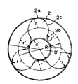
제1도는 본 발명에 따른 루우트 타입 펌프의 한 로우터의 프로우필을 나타낸 도면.1 shows a profile of one rotor of a root type pump according to the invention.
제2도는 제1도에 도시한 로우터를 채용한 펌프의 단면구조를 대략적으로 나타낸 도면.FIG. 2 is a diagram schematically showing a cross-sectional structure of a pump employing the rotor shown in FIG.
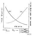
제3도는 인벌류우트곡선의 압력각(a)과 샤프트직경(d)에 대한 인벌류우트타입 로우터외측직경(D)의 비(D/d) 사이의 관계를 나타낸 도면.3 shows the relationship between the pressure angle (a) of the involute flow curve and the ratio (D / d) of the involute type rotor outer diameter (D) to the shaft diameter (d).
제4도는 샤프트직경(d)에 대한 외측직경(D)의 비(D/d), 샤프트 강도비(A) 그리고 일회전에 대한 이론적 배개량계수(K) 사이의 관계를 나타낸 도면.4 shows the relationship between the ratio (D / d) of the outer diameter (D) to the shaft diameter (d), the shaft strength ratio (A) and the theoretical displacement coefficient (K) for one revolution.
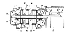
제5도는 다단구조에 제공된 것으로 본 발명에 따른 로우터를 갖는 루우트 타입 펌프에서 제1로우터를 구동하는 회전샤프트의 축을 따라 취한 단면도.5 is a cross-sectional view taken along the axis of a rotary shaft for driving a first rotor in a route type pump having a rotor according to the present invention provided in a multistage structure.
제6도는 제5도의 선 Ⅵ-Ⅵ을 따라 취한 단면도.6 is a sectional view taken along the line VI-VI of FIG.
제7도는 종래의 루우트 타입 펌프에서 로우터의 단면구조를 대략적으로 나타낸 도면이다.7 is a view schematically showing the cross-sectional structure of the rotor in the conventional root type pump.
* 도면의 주요부분에 대한 부호의 설명* Explanation of symbols for main parts of the drawings
2,3,22,23,32,42 : 로우터 2a,3a : 선단부2,3,22,23,32,42:
2b,3b : 루우트부, 2c,3c : 인벌류우트곡선부2b, 3b: route part, 2c, 3c: involute curve part
26, 27 : 회전샤프트 36,37 : 베어링26, 27: rotating
39 : 타이밍기어 50 : 흡입구39: timing gear 50: inlet
52 : 송출구52: outlet
본 발명은 진공펌프시스템에서 사용하기 위해 루우트(roots) 타입 펌프와 같은 루우트 타입 회전기계에 관한 것이다.The present invention relates to a root type rotary machine such as a roots type pump for use in a vacuum pump system.
루우트 타입 펌프와 같은 회전기계가 안정작동을 하도록 하기 위해 회전샤프트에 충분한 강도를 제공하는 것이 설계관점에서 가장 중요한 것이다. 그러나 로우터의 외측직경(D)에 대하여 회전샤프트의 직경(d)의 과도한 증가는 일회전에 대한 이론적인 배기량의 감소를 초래한다. 따라서, 배기량과 기계적강도를 고려하여 적절한 샤프트 직경(d)을 선정할 필요가 있다. 엔벌루우프, 인벌류우트 그리고 사이클 로이드 프로우필들은 루우트타입의 펌프의 로우터프로우필로써 일반적으로 알려져 있다. 엔벌루우프와 사이클 로이드 프로우필의 경우에는 회전샤프트직경(d) 즉 최단직경(로우트원의 직경)에 대한 로우터 외측직경(D)(선단원의 직경)의 비(D/d)가 근본적으로 결정되는 것에 반하여, 인벌류우트프로우필의 경우에는 비(D/d)가 어떤 범위내에서 인벌류우트곡선의 압력각(a)을 변화시키므로써 바람직하게 변할 수 있다.Providing sufficient strength to the rotating shaft to ensure stable operation of rotating machines such as rooted type pumps is of paramount importance in terms of design. However, an excessive increase in the diameter d of the rotary shaft relative to the outer diameter D of the rotor results in a decrease in the theoretical displacement for one revolution. Therefore, it is necessary to select the appropriate shaft diameter d in consideration of the displacement and mechanical strength. Envelopes, involutes and cycloid profiles are commonly known as rotor profiles for rooted pumps. In the case of envelope and cycloid profile, the ratio of rotation shaft diameter (d), ie the outer diameter of rotor (D) (diameter of tip circle) to the shortest diameter (diameter of circle circle), is basically determined. In contrast, in the case of the involute route profile, the ratio D / d can be preferably changed by changing the pressure angle a of the involute route within a certain range.
전형적인 종래의 인벌류우트타입의 로우터를 도시한 제7도에서 각 선단부(12a),(13a)는 인벌류우트곡선부(12c),(13c)를 가로지르는 로우터의 외측직경(선단원의 직경)의 원으로 한정되고, 이에 반하여 각 루우트 각(12b),(13b)는 인벌류우트곡선부(12c),(13c)를 가로지르고 또한 직경(d)의 원과 접촉하는 두원호(반경 rο)로 한정된다. 일회전에 대한 이론적인 배기량 크기는 하우징(11)과 로우터(12)사이로 한정되는 트랩핑공간(14)의 6배(삼엽 로우터의 경우)에 해당하며 다음과 같이 표현된다.In FIG. 7, which shows a typical conventional involute type rotor, each
V=KD²LV = KD²L
V : 일회전에 대한 이론적 배기량 크기V: theoretical displacement for one revolution
D : 로우터의 외측직경D: Outside diameter of rotor
L : 로우터 두께(로우터가 점유하는 공간의 깊이)L: Thickness of the rotor (depth of space occupied by the rotor)
K : 이론적 배기량 계수K: theoretical displacement factor
이론적 배기량 계수(K)는 로우터 프로우필에 의해 결정된다. 이론적 배기량 계수(K)의 극대화로 펌프의 배기량이 증가될 수 있다.The theoretical displacement factor K is determined by the rotor profile. By maximizing the theoretical displacement coefficient K, the displacement of the pump can be increased.
제7도에 예로써 도시된 형상을 갖는 상기 인벌류우트 타입 펌프의 경우에 밀폐된 공간(15)은 로우터(12)와 (13) 사이의 맞물림 결합의 영역으로 한정되고, 이 공간(15)은 트랩핑 과정중에 로우터(12)같은 여러 결점과, 동력소비의 증가 그리고 배기량의 감소를 초래하게 되며, 이에 따라 펌프작동의 손실을 초래하게 된다. 특히 종래기술은 압력각(a)이 더 작게됨에 따라 밀폐된 공간(15)이 증가된다는 문제점을 갖는다.In the case of the involute type pump having the shape shown by way of example in FIG. 7, the enclosed space 15 is limited to the area of the engagement engagement between the
상기의 상황에 비추어서 본 발명의 주목적은 상기 종래의 인벌류우트타입 로우터의 결점중 하나인 밀폐된 공간을 최소로 할 수 있도록 설계되고 동시에 인벌류우트타입의 로우터의 장점을 확실하게 하여 어떤 범위내에서 인벌류우트 곡선의 압력각(a)을 변화시켜서 샤프트직경(d)에 대한 로우터의 외측 직경(D)의 비(D/d)를 바람직하게 선정할 수 있는 인벌류우트 타입의 회전기계를 제공하는 것이다.In view of the above situation, the main object of the present invention is designed to minimize the enclosed space, which is one of the drawbacks of the conventional involute type rotor, and at the same time to assure the advantages of the involute type rotor within a certain range. A rotary machine of the involute type which can preferably select the ratio (D / d) of the outer diameter (D) of the rotor to the shaft diameter (d) by varying the pressure angle (a) of the involute curve To provide.
이렇게 하기 위하여 본 발명은 흡입구와 송출구와 한 단계에 공동으로 구성되는 적어도 두개 의 로우터를 갖는 하우징을 포함하고, 상기 로우터가 하우징내에 배치되며 서로 반대방향으로 회전하는 개개 샤프트를 갖고 흡입구로부터 송출구를 향하여 가스를 송출시키는 회전기계에 있어서, 각 로우터의 선단부가 로우터의 기초원(제1도에 도시된 직경(R)의 원)상에 중심을 두고 인벌류우트곡선과 비교적 부드럽게 접촉하는 원호(반경 r)로 한정되는 동시에, 각 로우터의 루우트부가 기초원상에 중심을 두고 인벌류우트곡선을 가로지르는 반경(r')(r+간극)의 원호로 한정되고, 로우터사이의 간극이 실질적으로 일정한 수준에서 유지되며, 직경(d)(루우트원의 직경)에 대한 각 로우터의 직경(D)(선단원의 직경)의 비(D/d)가 아래와 같이 표현되는 범위내에 있도록 선정되는 것을 특징으로 하는 루우트 타입 회전기계를 제공하는 것이다.To this end, the present invention comprises a housing having a suction inlet and an outlet and at least two rotors jointly configured in one step, the rotor being disposed in the housing and having individual shafts which rotate in opposite directions to each other. In a rotary machine that sends gas toward the head, a circular arc (radius) in which the tip of each rotor is relatively smoothly in contact with the involute curve centered on the rotor's base circle (circle of diameter R shown in FIG. 1). At the same time, the root portion of each rotor is defined by an arc of radius r '(r + gap), which traverses the involute route centered on the base circle, with a substantially constant gap between the rotors. And the ratio (D / d) of the diameter D (the diameter of the tip circle) of each rotor to the diameter d (the diameter of the root circle) is within the range represented by To provide a rotary-type machine that Lou agent being selected.
![]()
![]()
![]()
![]()
여기서, n은 로우터의 날개수이다 : n![]()
![]()
상기 장치에 의해 소정의 로우터 외측직경(D)을 위해 어떤 범위내에서 바람직하게 샤프트직경(d)을 선정할 수 있다. 샤프트 강도와 일회전에 대해 이론적 배기량 계수(제4도에 도시됨)을 고려하여 최적의 샤프트직경(d)이 선정될 수 있다. 따라서 진동과 소음의 발생, 동력소비의 증가, 배기량의 감소 등을 야기시킬 수 있는 밀폐된 공간이 실질적으로 없으며 실질적으로 일정한 로우터간극이 항상 확실하게 되도록 설계된 인벌류우트타입의 로우터를 만들 수 있다.The apparatus makes it possible to select the shaft diameter d preferably within a range for a given rotor outer diameter D. The optimum shaft diameter d can be selected taking into account the theoretical displacement coefficient (shown in FIG. 4) for shaft strength and one revolution. Therefore, it is possible to make an involute type rotor designed so that there is virtually no sealed space that can cause vibration and noise, increased power consumption, and reduced displacement, and that a substantially constant rotor gap is always ensured.
첨부도면을 참고하여 이하에서 본 발명의 일실시예를 설명한다.Hereinafter, an embodiment of the present invention will be described with reference to the accompanying drawings.
제1도은 본 발명에 따른 루우트 타입의 펌프의 한 로우터의 프로우필을 나타낸 것이며, 제2도는 제1도에 도시한 로우터를 채용한 루우트 타입 펌프의 단면구조를 대략적으로 나타낸 것이다. 도면에서 명확한 바와 같이 외측직경(D')의 선단부(2a),(3a)는 각각이 종래 인벌류우트타입 로우터의 기초원(직경 R)상에 중심을 두고 대응하는 인벌류우트곡선부(2c),(3c)와 접촉하는 원호(반경 r)로 한정되고, 마찬가지로 루우트부(2b),(3b)는 각각이 기초원상에 중심을 두고 반경(r')(r+간극)을 가지며 또 각각이 대응하는 인벌류우트곡선을 가로지르는 원호로 한정되며, 이에 따라 종래 인벌류우트타입 로우터의 샤프트직경(d)에 대해 외측직경(D)의 비(D/d) 보다 더 작은 비(D'/d')을 갖는 새로운 인벌류우트타입 로우터[외측직경 D'(D), 최단직경(d')(d)]를 얻을 수 있다.FIG. 1 shows a profile of one rotor of a root type pump according to the present invention, and FIG. 2 schematically shows a cross-sectional structure of a root type pump employing the rotor shown in FIG. As is clear from the figure, the leading
제3도는 인벌류우트타입 로우터의 샤프트직경에 대한 외측직경의 비(D/d)와 인벌류우트곡선의 압력각(a) 사이의 관계를 나타낸 것이다. 매개변수로써 채용된 압력각(a)으로 샤프트직경(d)에 대한 외측직경(D)의 비(D/d)를 얻는 것은 제3도로부터 가능하다. 압력각(a)이 인벌류우트곡선의 프로우필을 나타내기 때문에 샤프트직경(d)에 대한 외측직경(D)의 비(D/d)는 소정의 압력각(a)에 대해 일정하다. 따라서, 만일 압력각이 일정하다면 외측직경(D)에 대한 다른 외측직경(D')을 각각 갖는 두 로우터의 프로우필은 서로 유사하다. 이것은 소정의 로우터외측직경(D)이 일정할 때 압력각(a)이 로우터의 회전샤프트를 위해 필요한 샤프트직경(d)과 직경(D)으로부터 얻어진다면 로우터프로우필이 결정된다는 것을 의미한다.3 shows the relationship between the ratio D / d of the outer diameter to the shaft diameter of the involute type rotor and the pressure angle a of the involute curve. It is possible from FIG. 3 to obtain the ratio D / d of the outer diameter D to the shaft diameter d at the pressure angle a employed as a parameter. Since the pressure angle a represents the profile of the involute curve, the ratio D / d of the outer diameter D to the shaft diameter d is constant for the predetermined pressure angle a. Thus, if the pressure angles are constant, the profiles of the two rotors each having a different outer diameter D 'relative to the outer diameter D are similar to each other. This means that the rotor profile is determined if the pressure angle a is obtained from the shaft diameter d and diameter D necessary for the rotation shaft of the rotor when the predetermined rotor outer diameter D is constant.
로우터(2),(3)가 인벌류우트곡선부(2c),(3c)에서 서로 결합되어 밀폐되는 경우에는 실질적으로 일정한 간극이 인벌류우트곡선의 특성으로 유지되고, 실질적으로 일정한 간극은 루우트부(2b),(3b)를 한정하는 원호의 반경을 r'로 되도록 설정하여 선단부(2a), (3a)와 루우트부(3b),(2b)사이의 영역에서 항상 유지되며, r'는 선단부(2a), (3a)를 한정하는 원호의 반경(r)에 간극을 더하여 결정된다.When the
상기 설비는 제 2도에 도시한 바와 같이 종래기술의 결점중 하나인 밀폐된 공간(15)의 극소화를 가능하게 한다.This arrangement enables the minimization of the enclosed space 15, which is one of the drawbacks of the prior art as shown in FIG.
상기 설명한 바와 같이 샤프트직경(d)이 매개변수로써 인벌류우트곡선의 압력각(a)을 채용하여 소정의 로우터외측지경(D)을 위한 어떤 범위내에서 바람직하게 선정될 수 있기 때문에, 제4도에 도시한바와 같이 일회전에 대한 이론적 배기량 계수와 샤프트 강도를 고려하여 최적의 샤프트직경(d)를 선정할 수 있다. 더우기 최적의 샤프트직경(d)은 사이클로이드타입 로우터의 경우에서 샤프트직경(d)에 대한 외측직경(D)의 비(D/d)와 엔벌루우트타입 로우터의 경우에서의 비(D/d)사이의 다음 범위내에서 선정될 수 있으며, 여기서 비(D/d)를 갖는 두 타입의 로우터는 주로 다음과 같이 결정된다.As described above, since the shaft diameter d can be preferably selected within a certain range for the predetermined rotor outer diameter D by employing the pressure angle a of the involute curve as a parameter, As shown in the figure, the optimum shaft diameter d can be selected in consideration of the theoretical displacement coefficient for one revolution and the shaft strength. Furthermore, the optimum shaft diameter (d) is the ratio (D / d) of the outer diameter (D) to the shaft diameter (d) in the case of a cycloidal rotor and the ratio (D / d) in the case of an envelope type rotor. It can be selected within the following range, wherein the two types of rotors having a ratio (D / d) are mainly determined as follows.
(n+1)/(n-1)![]()
![]()
![]()
![]()
여기서, n은 로우터의 날개 개수이다 : n![]()
![]()
더우기 로우터(2)와 (3) 사이에는 실절적으로 밀폐된 공간이 없으며, 실질적으로 일정한 로우터간극이 항상 그들 사이에서 유지된다.Moreover, there is no practically enclosed space between the
제5와, 제6도는 다른 실시예와의 결합을 도시한 것이고, 여기서 본 발명이 다단진공펌프에 채용된 것이다. 이 다단진공펌프에서 공기는 예를 들면 진공챔버와 연통하고 있는 흡입구(50)를 통하여 두 개의 삼엽로우터(22), (23)로 구성된 제1단 펌프로 흡입된 다음에, 압력이 흡입구측 보다 다소 더 높은 송출구(52)로 배출된다.5 and 6 show a combination with another embodiment, in which the present invention is employed in a multistage vacuum pump. In this multistage vacuum pump, the air is sucked into the first stage pump consisting of two
계속하여 공기는 로우터(32)를 포함한 제2단펌프의 흡입구(도시하지 않음)로 인도된 다음에, 압력이 제2단펌프의 작동에 의해 더욱 더 높은 상태로 유지되는 송출구로 배출된다. 이런 방식으로 흡입구(50)로부터 흡입된 공기는 직렬로 배치된 다수 펌프를 통하여 지나서 공기 압력이 점차로 상승되고 공기가 최종단 펌프의 송출구로부터 배출된다. 이런 방식으로 흡입구(50)로부터 흡입된 공기는 직렬로 배치된 다수 펌프를 통하여 지나서 공기 압력이 점차로 상승되고 공기가 최종단 펌프의 송출구로부어 대기중으로 배출된다.Air is then directed to the inlet (not shown) of the second stage pump, including the
제5도에 도시된 실시예에서 하우징(21)에 견고하게 고착된 베어링(36),(37)에 의해 지지되는 한 회전샤프트(26)는 제1단 내지 제3단에 있는 제1로우터(22),(32),(42)를 구동한다. 회전샤프트(26)는 샤프트(26)의 일단에 작동 가능하게 연결된 모터(38)의 작동에 의해 구동된다.In the embodiment shown in FIG. 5, as long as the
회전샤프트(26)는 회전샤프트(26)의 다른단에 있는 타이밍기어(39)의 작동에 의해 제1단 내지 제3단에 있는 다른 또는 제2로우터(제6도에는 단지 제1단로우터(23)를 도시함)를 구동하는 다른 회전샤프트(27)와 동시에 회전하도록 배열된다.The
제5도에 도시한 다단펌프에서 각 회전샤프트(26),(27)에 걸리는 하중은 각 샤프트가 다수 로우터를 구동하기 때문에 증가할 것이다. 그러나, 본 발명에서는 각 회전샤프트의 최대응력이 인벌류우트타입로우터를 채용하므로써 또 인벌류우트곡선의 압력각을 위한 적절한 값을 선정하므로써 소정의 값보다 더 작게 되도록 하기 위해 샤프트직경(d)을 선정할 수 있고, 이에 따라 회전샤프트에 적절한 기계적 강도를 제공할 수 있다. 더욱이 로우터의 선단부 및 루우트부를 원호로 한정하므로써 밀폐된 공간을 실질적으로 제거할 수 있고, 이에 따라 진공과 소음의 발생을 극소화할 수 있다.In the multistage pump shown in FIG. 5, the load on each of the
상기 실시예에서 삼엽로우터를 채용하고 있지만 본 발명은 세 개 이상의 날개를 가진 어떤 로우터에도 적용할 수 있다. 홈이나 또는 원호의 외부에 있는 다른 국부영역은 각 로우터의 선단부에 형성될 수 있다. 상기 실시예에서 본 발명이 루우트타입 펌프에 적용되었지만, 본 발명은 루우트 타입 펌프에 더하여 루우트 타입 유량계와 같은 루우트 타입 회진기계에 널리 적용될 수 있다.Although the trilobal rotor is employed in the above embodiment, the present invention can be applied to any rotor having three or more wings. Grooves or other local regions outside the arc can be formed at the tip of each rotor. In the above embodiment, the present invention is applied to a root type pump, but the present invention can be widely applied to a root type revolving machine such as a root type flow meter in addition to the root type pump.
상기 설명한 바와 같이 본 발명은 다음 장점들을 제공한다.As described above, the present invention provides the following advantages.
소정의 로우터외측직경(D)에 대해 제4도에 예로써 도시된 바와 같이 일회전에 대한 이론적 배기량계수와 샤프트 강도를 고려하여 어떤 범위내에서 최적의 샤프트직경(d)을 선정할 수 있다. 따라서, 진동 및 소음의 발생, 동력소비의 증가, 그리고 배기량의 감소 등을 야기할 수 있는 밀폐된 공간이 실질적으로 없으며 또 실질적으로 일정한 로우터간극이 항상 확실하게 되도록 인벌류우트타입 로우터를 채용하는 루우트 타입 펌프를 제공할 수 있다.As shown by way of example in FIG. 4 for a given rotor outer diameter D, the optimum shaft diameter d can be selected within a range in consideration of the theoretical displacement coefficient for one revolution and the shaft strength. Therefore, a loop that employs an involute type rotor so that there is substantially no enclosed space that can cause vibration and noise, increased power consumption, and reduced displacement, and that a substantially constant rotor clearance is always ensured. Type pump can be provided.
Claims (2)
Applications Claiming Priority (3)
| Application Number | Priority Date | Filing Date | Title |
|---|---|---|---|
| JP87-235274 | 1987-09-19 | ||
| JP62-235274 | 1987-09-19 | ||
| JP62235274A JPS6477782A (en) | 1987-09-19 | 1987-09-19 | Rotary machine of roots type |
Publications (2)
| Publication Number | Publication Date |
|---|---|
| KR890005393A KR890005393A (en) | 1989-05-13 |
| KR970009957B1 true KR970009957B1 (en) | 1997-06-19 |
Family
ID=16983670
Family Applications (1)
| Application Number | Title | Priority Date | Filing Date |
|---|---|---|---|
| KR1019880012088A KR970009957B1 (en) | 1987-09-19 | 1988-09-19 | Roots type rotary compressor |
Country Status (5)
| Country | Link |
|---|---|
| US (1) | US4943214A (en) |
| EP (1) | EP0308827B1 (en) |
| JP (1) | JPS6477782A (en) |
| KR (1) | KR970009957B1 (en) |
| DE (1) | DE3871053D1 (en) |
Families Citing this family (20)
| Publication number | Priority date | Publication date | Assignee | Title |
|---|---|---|---|---|
| AT397134B (en) * | 1991-02-19 | 1994-02-25 | Hoerbiger Ventilwerke Ag | VALVE |
| GB9200217D0 (en) * | 1992-01-07 | 1992-02-26 | Snell Michael J | Water turbines |
| DE19849804C2 (en) * | 1998-10-29 | 2001-10-04 | Voith Turbo Kg | Series for gear pumps with different delivery rates and processes for the production of the individual gear pumps of the series |
| US6644947B2 (en) * | 2002-03-14 | 2003-11-11 | Tuthill Corporation | Wave tooth gears using identical non-circular conjugating pitch curves |
| CN100439716C (en) * | 2002-12-31 | 2008-12-03 | 北京依品非标准设备有限公司 | Involute and straight claw type rotor structure for oilless vacuum pump |
| GB0319344D0 (en) * | 2003-08-18 | 2003-09-17 | Boc Group Plc | Reducing exhaust pulsation in dry pumps |
| US10487828B2 (en) * | 2004-10-12 | 2019-11-26 | Joe Dick Rector | Self-priming positive displacement pump with sectioned dividing wall |
| JP4732833B2 (en) * | 2005-08-22 | 2011-07-27 | 樫山工業株式会社 | Screw rotor and vacuum pump |
| JP4767625B2 (en) * | 2005-08-24 | 2011-09-07 | 樫山工業株式会社 | Multi-stage Roots type pump |
| JP4613811B2 (en) * | 2005-12-09 | 2011-01-19 | 株式会社豊田自動織機 | Roots fluid machinery |
| TWI438342B (en) * | 2006-07-28 | 2014-05-21 | Lot Vacuum Co Ltd | Complex dry vacuum pump having root and screw rotors |
| DE102007023949A1 (en) * | 2007-05-23 | 2008-11-27 | Scepanik, Hans-Jürgen | Rotary blower used for air compression, has three sets of meshing teeth on each of two shafts, operating in phased sequence in separate chambers, to drive parallel flows |
| EP2551649A1 (en) * | 2011-07-27 | 2013-01-30 | Trimec Industries Pty. Ltd. | Improved positive displacement flow meter |
| JP5542873B2 (en) * | 2012-06-06 | 2014-07-09 | 太陽機械工業株式会社 | Gear and gear design method |
| DE102013110091B3 (en) * | 2013-09-13 | 2015-02-12 | Pfeiffer Vacuum Gmbh | Roots pump with two rotors |
| CN104963855A (en) * | 2015-04-14 | 2015-10-07 | 上海大学 | Method for generating molded lines of multiphase flow medium-conveying screw type rotor pumps |
| JP6120468B1 (en) * | 2016-06-29 | 2017-04-26 | Osセミテック株式会社 | Gas transfer body for vacuum pump and vacuum pump using the same |
| CN106194716B (en) * | 2016-09-18 | 2018-10-26 | 中国石油大学(华东) | A kind of three elliptic leaf camber cam followers |
| CN111197574B (en) * | 2018-11-20 | 2021-07-23 | 宿迁学院 | High-performance novel parabolic rotor for pump |
| IT202100012836A1 (en) * | 2021-05-18 | 2022-11-18 | Roberto Manzini | LOBE VOLUMETRIC PUMP |
Family Cites Families (13)
| Publication number | Priority date | Publication date | Assignee | Title |
|---|---|---|---|---|
| US1442018A (en) * | 1921-05-13 | 1923-01-09 | Wendell Evert Jansen | Rotor for rotary pumps |
| US3089638A (en) * | 1958-12-01 | 1963-05-14 | Dresser Ind | Impellers for fluid handling apparatus of the rotary positive displacement type |
| US3371856A (en) * | 1966-03-24 | 1968-03-05 | Fuller Co | Modified cycloidal impeller |
| JPS52111007A (en) * | 1976-03-13 | 1977-09-17 | Ebara Corp | Shaft stabilizing of rotary pump |
| US4210410A (en) * | 1977-11-17 | 1980-07-01 | Tokico Ltd. | Volumetric type flowmeter having circular and involute tooth shape rotors |
| GB2018897A (en) * | 1978-03-31 | 1979-10-24 | Evro Johnson Pumps Ltd | Rotary positive-displacement pumps |
| JPS5829999B2 (en) * | 1978-03-31 | 1983-06-25 | 工業技術院長 | Solid fuel gasification equipment |
| JPS5591786A (en) * | 1978-12-29 | 1980-07-11 | Ebara Corp | Rotor for rotary piston pump |
| GB2088957B (en) * | 1980-12-05 | 1984-12-12 | Boc Ltd | Rotary positive-displacement fluidmachines |
| GB2125109A (en) * | 1982-08-10 | 1984-02-29 | Paul William Nachtrieb | Rotary positive-displacement fluid-machines |
| JPS6014945A (en) * | 1983-07-05 | 1985-01-25 | イオニ−株式会社 | Rice refining apparatus |
| JPS61197793A (en) * | 1985-02-26 | 1986-09-02 | Ebara Corp | Cooling method in multi-stage root type vacuum pump |
| JPS62189388A (en) * | 1987-01-30 | 1987-08-19 | Ebara Corp | Multistage roots type vacuum pump |
-
1987
- 1987-09-19 JP JP62235274A patent/JPS6477782A/en active Granted
-
1988
- 1988-09-16 EP EP88115237A patent/EP0308827B1/en not_active Expired - Lifetime
- 1988-09-16 DE DE8888115237T patent/DE3871053D1/en not_active Expired - Lifetime
- 1988-09-19 KR KR1019880012088A patent/KR970009957B1/en not_active IP Right Cessation
-
1989
- 1989-12-15 US US07/449,420 patent/US4943214A/en not_active Expired - Lifetime
Also Published As
| Publication number | Publication date |
|---|---|
| EP0308827A2 (en) | 1989-03-29 |
| KR890005393A (en) | 1989-05-13 |
| EP0308827B1 (en) | 1992-05-13 |
| JPS6477782A (en) | 1989-03-23 |
| US4943214A (en) | 1990-07-24 |
| EP0308827A3 (en) | 1989-10-25 |
| DE3871053D1 (en) | 1992-06-17 |
| JPH0310040B2 (en) | 1991-02-12 |
Similar Documents
| Publication | Publication Date | Title |
|---|---|---|
| KR970009957B1 (en) | Roots type rotary compressor | |
| EP0256234A2 (en) | Vacuum generating system | |
| EP1910682B1 (en) | Vacuum pump | |
| US20070048162A1 (en) | Multistage root type pump | |
| EP1462653B1 (en) | Internal gear pump | |
| CN109642574B (en) | Dry compression type vacuum pump | |
| JPH08144977A (en) | Compound dry vacuum pump | |
| EP0256739A1 (en) | Turbo-molecular pump | |
| JPH01138397A (en) | Molecular pump | |
| JPH05195957A (en) | Vacuum pump | |
| US5056995A (en) | Displacement compressor with reduced compressor noise | |
| JP3048583B2 (en) | Pump stage for high vacuum pump | |
| US5876193A (en) | Oil pump rotor having a generated cycloid curve | |
| KR19980081230A (en) | Oil pump rotor | |
| KR20060047511A (en) | Screw fluid machine | |
| JP4388167B2 (en) | Improvement of vacuum pump | |
| US4732530A (en) | Turbomolecular pump | |
| US5813844A (en) | Oil pump rotor having a generated tooth shape | |
| US5135373A (en) | Spur gear with epi-cycloidal and hypo-cycloidal tooth shapes | |
| JP2003161277A (en) | Multi-stage dry vacuum pump | |
| JPH08189485A (en) | Screw machine | |
| KR100876029B1 (en) | Rotating piston device for compressible media | |
| JPH05312173A (en) | Dry vacuum pump | |
| JPH07305684A (en) | Operation noise reducing structure of internal gear-type liquid pump using trochoid tooth | |
| US3311291A (en) | Helical screw compressors |
Legal Events
| Date | Code | Title | Description |
|---|---|---|---|
| A201 | Request for examination | ||
| E902 | Notification of reason for refusal | ||
| E902 | Notification of reason for refusal | ||
| G160 | Decision to publish patent application | ||
| E701 | Decision to grant or registration of patent right | ||
| GRNT | Written decision to grant | ||
| FPAY | Annual fee payment |
Payment date: 20080925 Year of fee payment: 12 |
|
| LAPS | Lapse due to unpaid annual fee |