KR970007233B1 - Liquid distributor assembly for packed tower - Google Patents
Liquid distributor assembly for packed tower Download PDFInfo
- Publication number
- KR970007233B1 KR970007233B1 KR1019890015852A KR890015852A KR970007233B1 KR 970007233 B1 KR970007233 B1 KR 970007233B1 KR 1019890015852 A KR1019890015852 A KR 1019890015852A KR 890015852 A KR890015852 A KR 890015852A KR 970007233 B1 KR970007233 B1 KR 970007233B1
- Authority
- KR
- South Korea
- Prior art keywords
- shaped channel
- liquid
- shaped
- grooves
- flow
- Prior art date
Links
Images


Classifications
-
- B—PERFORMING OPERATIONS; TRANSPORTING
- B67—OPENING, CLOSING OR CLEANING BOTTLES, JARS OR SIMILAR CONTAINERS; LIQUID HANDLING
- B67D—DISPENSING, DELIVERING OR TRANSFERRING LIQUIDS, NOT OTHERWISE PROVIDED FOR
- B67D99/00—Subject matter not provided for in other groups of this subclass
-
- B—PERFORMING OPERATIONS; TRANSPORTING
- B01—PHYSICAL OR CHEMICAL PROCESSES OR APPARATUS IN GENERAL
- B01D—SEPARATION
- B01D3/00—Distillation or related exchange processes in which liquids are contacted with gaseous media, e.g. stripping
- B01D3/008—Liquid distribution
-
- B—PERFORMING OPERATIONS; TRANSPORTING
- B01—PHYSICAL OR CHEMICAL PROCESSES OR APPARATUS IN GENERAL
- B01J—CHEMICAL OR PHYSICAL PROCESSES, e.g. CATALYSIS OR COLLOID CHEMISTRY; THEIR RELEVANT APPARATUS
- B01J4/00—Feed or outlet devices; Feed or outlet control devices
- B01J4/001—Feed or outlet devices as such, e.g. feeding tubes
-
- F—MECHANICAL ENGINEERING; LIGHTING; HEATING; WEAPONS; BLASTING
- F28—HEAT EXCHANGE IN GENERAL
- F28F—DETAILS OF HEAT-EXCHANGE AND HEAT-TRANSFER APPARATUS, OF GENERAL APPLICATION
- F28F25/00—Component parts of trickle coolers
- F28F25/02—Component parts of trickle coolers for distributing, circulating, and accumulating liquid
- F28F25/04—Distributing or accumulator troughs
Landscapes
- Chemical & Material Sciences (AREA)
- Engineering & Computer Science (AREA)
- Chemical Kinetics & Catalysis (AREA)
- Physics & Mathematics (AREA)
- Thermal Sciences (AREA)
- Mechanical Engineering (AREA)
- General Engineering & Computer Science (AREA)
- Organic Chemistry (AREA)
- Vaporization, Distillation, Condensation, Sublimation, And Cold Traps (AREA)
- Feeding, Discharge, Calcimining, Fusing, And Gas-Generation Devices (AREA)
- Physical Or Chemical Processes And Apparatus (AREA)
Abstract
내용없음No content
Description
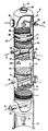
제1도는 본 발명에 따라 구성된 액체흐름 분배홈부의 한 실시예, 및 충전탑 내부를 나타내기 위하여 각 부분을 단면을 취해 나타낸 충전탑의 사시도 이다.1 is a perspective view of an embodiment of a liquid flow distribution groove portion constructed in accordance with the present invention, and a packed column showing a cross section of each part to show the inside of the packed tower.
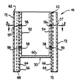
제2도는 본 발명에 따라 구성되고, 양쪽에 제거 가능한 다수개의 분배튜브 어셈블리들을 갖고 있는 제1도의 액체흐름 분배홈부를 선 2-2를 따라 단면을 취해 나타낸 확대측단면도이다.FIG. 2 is an enlarged side cross-sectional view of the liquid flow distribution groove portion of FIG. 1 taken along line 2-2, constructed in accordance with the present invention and having a plurality of removable tube assemblies removable on both sides.
제3도는 제2도의 선 3-3을 따라 단면을 취해 나타낸 분배홈부의 확대 평단면도로서, 제거 가능한 분배튜브 어셈블리들의 배치상태를 나타낸 도면이다.FIG. 3 is an enlarged planar cross-sectional view of the dispensing groove part taken along the line 3-3 of FIG. 2, showing the arrangement of removable dispensing tube assemblies.
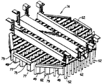
제4도는 본 발명에 따라 조립된 다수개의 분배튜브를 나타낸 본 발명의 흐름 분배열의 학대 사시도 이다.4 is an abusive perspective view of the flow distribution row of the present invention showing a plurality of distribution tubes assembled in accordance with the present invention.
제5도는 제거 가능한 분배튜브 어셈블리의 구조를 나타낸 제2도의 흐름 분배홈부의 부분확대 평면도이다.5 is a partially enlarged plan view of the flow distribution groove of FIG. 2 showing the structure of the removable dispensing tube assembly.
제6도는 제2도의 홈부의 확대측면도로서, 이홈부를 통과하는 액체의 흐름을 나타낸 도면이다.FIG. 6 is an enlarged side view of the groove portion of FIG. 2 showing the flow of liquid through the groove portion.
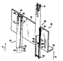
제7도는 제6도의 튜브 어셈블리의 사시도로서, 본 발명에 따라 튜브 어셈블리로 부터 그의 일부가 제거 되어져 빼내어진 상태를 나타낸 도면이다.FIG. 7 is a perspective view of the tube assembly of FIG. 6, showing a state in which a part thereof is removed from the tube assembly according to the present invention.
* 도면의 주요부분에 대한 부호의 설명* Explanation of symbols for main parts of the drawings
10 : 충전탑 12 : 원통형탑10: packed tower 12: cylindrical tower
14 : 충전베드층 18 : 액제측 공급통로14: filling bed layer 18: liquid side supply passage
20 : 측류송출통로 26 : 증기배출통로20: side flow discharge passage 26: steam discharge passage
30 : 하류송출통로 32 : 측류증기공급통로30: downstream discharge passage 32: side steam supply passage
34 : 역류복귀통로 36,48 : 액체분배장치34:
38 : 상부 충전베드 41 : 지지그리드38: upper filling bed 41: support grid
42 : 액체재분배장치 44 : 중간지지판42: liquid redistribution device 44: intermediate support plate
49 : 홈부 62 : 적하튜브어셈블리49: groove 62: dropping tube assembly
99 : 핀 어셈블리99: pin assembly
본 발명은 증기-액체 접촉충전탑에 사용되는 액체흐름 분배장치 및 액체흐름 분배방법에 관한 것으로서, 특히 증기와 액체흐름이 상호 역류로서 결합되어지게되는 증기-액체 접촉충전탑의 분배튜브 어셈블리에 관한 것이다.The present invention relates to a liquid flow distribution device and a liquid flow distribution method for use in a vapor-liquid contacting tower, and more particularly, to a distribution tube assembly of a vapor-liquid contacting tower in which vapor and liquid flow are combined as countercurrents. will be.
종래의 기술에 있어서 대량전달, 열의전달, 공급 원료성분의 밀폐분류 및/또는 선별 및 기타 단위 공정들을 수행하기 위하여 역류흐름을 이용하여 개스와 액체를 서로 접촉시키는 여러가지 형식의 교환충전탑을 사용하는 것이 공지되어있다.In the prior art, various types of exchange charging towers are used, in which gas and liquid are brought into contact with each other using a backflow to perform mass transfer, heat transfer, closed sorting and / or sorting of feedstock components and other unit processes. It is known.
효과적인 공정의 수행을 위해 대량전달, 열전달, 액체증발, 및/또는 응축을 요구함으로써, 일부 액체가 면적 및 부피를 한정하는 최소치수의 특별한 구역내에서 최소의 압려강하를 통하여 냉각되어질 수 있게 된다.By requiring mass transfer, heat transfer, liquid evaporation, and / or condensation to perform an effective process, some liquids can be cooled through a minimum drop in a special zone of minimum dimensions defining area and volume.
이러한 것들은 효과적인 공정의 수행을 위한 선결조건으로서, 밀폐분류에 있어 필요한 것들이다.These are prerequisites for the effective performance of the process and are necessary for closed classification.
이러한 이유로써, 상기 교환탑들내에서의 증기와 액체의 역류흐름은 종래의 기술에 있어 상기의 증기와 액체의 접촉방법이 설정되어지게된다.For this reason, the countercurrent flow of vapor and liquid in the exchange towers is such that the method of contacting the vapor and liquid in the prior art is established.
실제적인 증기와 액체의 접촉에 있어 교환탑내에 충전베드의 사용을 필요로 하게 된다. 그러면, 액체는 가장 타당성 있는 방식으로 충전베드의 윗쪽에서 분배되어지고, 반면에 증기가 탑의 하부내의 충전베드 밑에서 분배되어지게된다.The actual contact of vapor and liquid requires the use of a packed bed in the exchange column. The liquid is then dispensed above the fill bed in the most feasible manner, while steam is dispensed under the fill bed in the bottom of the tower.
이와같은 방식으로, 충전베드를 통하여 아랫쪽으로 액체가 똑똑 떨어져 흘러 내려와 상승하는 증기와 마주치게 되어 액체와 증기의 접촉 및 상호작용이 이루어지게 된다.In this way, the liquid drips down downwardly through the filling bed and encounters rising steam, which causes contact and interaction between the liquid and the steam.
충전베드의 형태가 압력강하, 증기와 액체의 접촉효율, 및 공정탑내에서 발생하는 에너지 및 부수물의 전달을 결정하게된다.The shape of the packed bed determines the pressure drop, the contact efficiency of the vapor with the liquid, and the transfer of energy and ancillary water that occurs within the process tower.
충전베드 양끝에서 부터의 증기와 액체의 보다 효과적인 분배뿐만 아니라 이러한 분배작용을 유지시키기 위한 수단이 효과적인 작용에 비해 부족한 면이 있다. 효과적인 초기 증기 및 액체 분배 및 충전베드를 통한 상기 분배작용의 유지는 효율을 최대화시킬 수 있도록 하기 위하여 구성되어진 동일한 혼합영역에서 행해지게된다. 효율성은 작업비용 및 품질에 즉시 영향을 주게된다. 이러한 이유때문에, 종래 기술의 무수한 충전설계안들은 종래의 교환탑에 있어서는 효과가 있었다. 그러나, 충전효율은 통과되는 증기 및 액체의 효율에 의해 상당부분 제한되어진다.There is a lack of effective distribution of vapor and liquid from both ends of the packed bed as well as a means for maintaining this distribution compared to the effective operation. Effective initial vapor and liquid dispensing and maintenance of the dispensing action through the packed bed is done in the same mixing zone that is configured to maximize efficiency. Efficiency immediately impacts cost and quality. For this reason, a myriad of filling designs of the prior art have worked for conventional exchange towers. However, the filling efficiency is largely limited by the efficiency of the vapor and liquid passing through.
예를들어, 충전베드 부 전역에 증기 또는 액체중 어느하나라도 균등하게 분배되어지지 않는다면 분배작용이 이루어지지 않는 충전 부분의 사용이 행해지지 않게 되므로, 이는 즉시 효율성 및 작용의 비용효과면에 영향을 끼치게된다.For example, if any of the vapor or liquid is not evenly distributed throughout the filling bed section, the use of non-dispensing filling will not occur, which immediately affects the efficiency and cost effectiveness of the action. Get stuck.
충전베드의 깊이는 제품기준 및 작동비용의 설정에 있어 결정적인 것이며, 증기와 액체가 균등하게 분배되어지지 않는 것 및/또는 충전베드 내의 균일함을 유지시키지 못하게되면 이는 특히 석유 정재산업에 있어서 심각한 결과들을 초래하게된다.The depth of the filling bed is decisive in the setting of product standards and operating costs, and if the vapor and liquid are not evenly distributed and / or fail to maintain uniformity in the filling bed, this is a serious consequence, especially in the oil refining industry. Will cause them.
충전베드들 자체에서 생각하면, 액체분배장치는 탑 내부요소중에서 가장중요한 유니트가 된다. 충전탑의 성능에 있어서의 결함은 주로 불순물로 인한 고장 또는 균일하지 않은 분배작용과 같은 액체분배상의 문제들로 인하여 발생하게 되고, 따라서 적합한 액체분배장치의 선택이 순조로운 플랜트의 작동에 있어 결정적인 요인이다.Thinking in the filling beds themselves, the liquid distributor is the most important unit of the tower's internal components. Defects in packed tower performance arise mainly from problems with liquid distribution, such as failures due to impurities or uneven distribution, so the selection of the appropriate liquid distribution device is a decisive factor in the smooth operation of the plant. to be.
따라서, 작동상의 문제를 생각할 때, 이에는 분배장치의 홈부분들의 수준이 어떻게 유지되어지는가, 바닥부분이 어떻게 균등하게 되어지는가 및 액체가 홈부분으로부터 그 밑의 충전베드들로 분배되어지게되는 수단등과 같은 분배장치의 기능적인 문제들을 포함하게 된다.Thus, in view of operational problems, this includes how the level of the grooves of the dispensing device is maintained, how the bottom is equalized and the means by which liquid is distributed from the groove to the filling beds below it. And functional problems of the distribution device.
또한, 고려되어지는 것은 상승하는 증기가 분배되어지게될 액체의 위에 있게되는 효과이다. 증기흐름 영역이 제한되어지게 되면, 흐름 속도가 하강흐름 패턴을 방해하는 점까지 상승되어질 수도 있다. 액체는 주위에 날려지는 형태가 되고, 이러한 상태는 공정탑내의 무효화 및 균일하지 않은 분배를 초래하게 된다.Also contemplated is the effect that the rising vapor is above the liquid to be dispensed. If the vapor flow zone is limited, the flow rate may be raised to the point where it hinders the downward flow pattern. The liquid is in the form of being blown around and this condition leads to invalidation and non-uniform distribution in the process column.
종래의 액체분배장치는 일반적으로 충전베드 위에서 스프레이형태로 액체를 분산시키도록된 다수개의 오리피스 스피레이헤드를 포함하고 있다. 교환탑안에 다수개의 무작위의 충전요소들이 배치된 덤프 패킹의 사용에 있어, 상기와 같은 액체분배 기술이 때때로 효과적이다. 이것은 특히 효율 파라미터들이 결정적인 요인이 아닌 경우에는 특히 그렇다.Conventional liquid dispensing devices generally include a plurality of orifice spilayheads adapted to disperse liquid in the form of a spray on a filling bed. In the use of dump packings in which a plurality of random filling elements are arranged in an exchange tower, such a liquid dispensing technique is sometimes effective. This is especially the case when efficiency parameters are not the determining factor.
그러나, 본 발명의 양수인에게 양도된 미합중국 특허 제4,604,247호에 기술된 것과 같은 고효율을 패킹의 경우에 있어서는, 균일한 액체 및 개스의 분배가 극히 중요한 요소가 된다.However, in the case of packing high efficiency such as described in US Pat. No. 4,604,247, assigned to the assignee of the present invention, uniform distribution of liquids and gases is extremely important.
전술한 특허에 기술되어진 형식의 고효율 패킹의 비용이 적합한 증기-액체 분배에 대한 주의를 요하게 된다.The cost of high-efficiency packing of the type described in the above patents requires attention to proper vapor-liquid distribution.
증기와 액체 사이의 비균질의 상호작용부가 조금이라도 있게 되면 비용이 비싸게되고 그 효율 패킹의 사용과 일치하지 않는 낭비손실이 있게 되며, 증기-액체 접촉면 및 균일성 양쪽모두가 적합한 작용에 있어 기대되고 필요하게된다.Any minor inhomogeneous interaction between the vapor and the liquid becomes expensive and results in waste losses that are inconsistent with the use of the efficiency packing, and both the vapor-liquid contact and uniformity are expected and necessary for proper operation. Will be done.
전술한 미합중국 특허에 기술된 바와같은 고효율 패킹은 채널안에 배치된 주름이 잡혀 홈이 형성되어 있는 시이트를 양립시킴으로써 한정되어지는 채널들을 통한 역류의 증기-액체 흐름을 필요로 하게된다.High-efficiency packing as described in the above-mentioned US patent requires a vapor-liquid flow of backflow through the channels, which is defined by compatibilizing the pleated, grooved sheet disposed in the channel.
초기의 액체 또는 개스분배가 특히 주름이 잡혀 홈이 형성되는 패턴으로 되지 않는다면, 액체 및 증기가 패킹의 채워지지 않은 부분을 통해 상호 작용하고 그 안으로 옮겨지도록 될 때까지는 많은 표면적이 패킹내에서 손실되어지게 된다.If the initial liquid or gas distribution is not particularly corrugated to form a grooved pattern, a large amount of surface area is lost in the packing until liquid and vapor are allowed to interact and move into the unfilled portion of the packing. You lose.
오직 적합한 증기 및 액체분배장치를 사용하는 것이 효과적이며, 종래의 덤프 패킹 뿐만아니라 고효율 패킹의 효과적인 이용이 확보되어지게된다.It is effective to use only suitable vapor and liquid dispensing devices, ensuring effective use of high efficiency packing as well as conventional dump packing.
대체적으로, 스프레이오리피스, 파이프, 구멍이 나있는 플레이트, 구멍이 나있는 홈 및 노즐등을 이용해 액체를 배출 및 분배하는 것은 공지되어있다.In general, it is known to discharge and distribute liquids using spray orifices, pipes, perforated plates, perforated grooves and nozzles.
개스가 적합한 증기 분배를 제공하기 위하여 부수적으로 상승하는 난류형태로 배출되어진다.The gas is discharged in an incidentally rising turbulence form to provide a suitable vapor distribution.
많은 종래의 스템들이 일반적으로 충전베드의 대부분이 다소의 증기 및 다소의 액체의 분배에 있어 효과적일지라도, 보다 정교한 분배장치를 사용하지 않고는 균일한 분배가 통상적으로 이루어질 수 없게 된다.Although many conventional stems generally are effective in dispensing some steam and some liquid, most of the filling beds will not normally be able to achieve uniform dispensing without the use of more sophisticated dispensing devices.
예를들어, 개스가 충전베드 아래의 인접하는 여러부분안으로 등압으로 주입되지 않고는 충전베드를 통해 윗쪽으로 흐르는 다량의 증기흐름이 균일해질 수 없다.For example, a large amount of vapor flow upwards through the fill bed cannot be uniform without gas being injected isostatically into adjacent portions below the fill bed.
랜덤 증기 배출은 단순히 충전베드의 하부를 통과하는 비균일한 양의 증기를 분배하지만, 분배의 균일성을 어떤 방식으로든 보장할 수 없다.Random vapor discharge merely distributes non-uniform amounts of steam passing through the bottom of the filling bed, but cannot guarantee uniformity of distribution in any way.
마찬가지로 충전베드위로 단순한 액체의 분무는 비록 이것이 모든 충전베드표면들을 젖게하는 데는 효과적으로 작용하나, 때때로 일정 충전베드 영역에는 많이 흐르고, 다른 영역에는 적게 흐르게되는 액체흐름의 높은 집중성의 결과를 초래하게된다.Similarly, a simple spray of liquid onto the filling bed results in a high concentration of liquid flow that sometimes flows largely in some filled bed areas and less in other areas, although this works effectively to wet all the filled bed surfaces.
이것은, 물론, 스프레이 장치에 좌우되는 것이다.This, of course, depends on the spray device.
오리피스 분배장치들은 대체로 다른형식의 분배장치들보다 충전하는데 있어 좀더 민감하며, 충전은 탑안으로의 균일하지 않은 관개(irrigation)를 초래하게된다.Orifice dispensing devices are generally more sensitive to filling than other types of dispensing devices, and filling results in uneven irrigation into the tower.
제조과정중에 발생하는 분배장치 팬 내의 표면의 불균일성으로 인하여 흐름 저항을 증가시키게 되거나 또는 분명한 결점을 이루는 팬의 바닥부를 따른 액체흐름을 야기시키게 된다.Unevenness of the surface in the distributor pan during the manufacturing process may increase the flow resistance or cause liquid flow along the bottom of the pan, which is an obvious drawback.
다른 영역의 흐름은 감소하고 한 영역내로 흐름이 집중하게 되는 흐름의 불균일성은 해로운 것이다. 액체를 분무시키기 위한 구멍들 또는 노즐들이 있는 지류파이프들이 설치되어있는 헤더들로 구성된 파이프 분배장치들이 발견되었는데, 이 경우 때때로 액체가 너무 미세하게 분배 되어지게된다.The nonuniformity of the flow, which reduces the flow in the other zone and concentrates the flow into one zone, is detrimental. Pipe distributors have been found that consist of headers equipped with feeder pipes with holes or nozzles for spraying liquid, in which case the liquid is sometimes dispensed too finely.
미세한 액체의 방울들이 역류개스 흐름에 의해 탑의부로 이동되어 진다.Droplets of fine liquid are moved to the top of the tower by countercurrent gas flow.
이것은 액체가 충전 베드와의 접촉이 이루어지는 것을 방지해준다.This prevents the liquid from making contact with the filling bed.
액체접촉이 충전의 목적으로, 상기의 결과는 전체적으로 액체분배장치의 목적을 저해하게된다.For the purpose of liquid contact filling, the above results impair the overall purpose of the liquid distributor.
노즐을 통한 액체흐름의 5%정도는 20psi의 압력 강하상태에서 연무로 변환되어질 수 있다.About 5% of the liquid flow through the nozzle can be converted to fumes at a pressure drop of 20 psi.
또한, 파이프 분배장치에 설치된 노즐은 일정영역에서는 흐름이 증가되는 결과를 초래하는 오버랩핑 스프레이패턴을 발생할 수 있음을 알아야 한다.It is also to be understood that the nozzles installed in the pipe distribution apparatus may generate overlapping spray patterns which in some areas result in increased flow.
또한, 스프레이 헤더들이 특별한 충전 형식에 좌우되어 수평하게 분산시키기 이전에 충전을 통하여 직립으로 통과하게되는 속도에서 액체를 내뿜게된다.In addition, the spray headers exhale liquid at a rate that passes through the filling to the upright prior to dispersing horizontally, depending on the particular fill type.
이러한 문제점들이 각종의 충전탑의 규격, 충전물, 높이, 재료 및 시스템에 있어 필요한 다수의 액체 분배 포인트들의 결정적인 요점들과 마찬가지로 중요하다.These issues are just as important as the critical points of the many liquid distribution points needed for various packed tower specifications, fills, heights, materials and systems.
패킹의 무게는 패킹 파손의 원인이 되므로 패킹의 높이를 너무 크게 하지 않는 것이 필수적이다.Since the weight of the packing causes packing damage, it is essential not to increase the packing height too much.
그러나, 패킹부들 사이의 액체의 재분배장치들이 고가이고 대량 전달을 위해서는 그만큼의 높이를 선택해야한다.However, the redistributors of the liquid between the packings are expensive and must be selected for that height for bulk delivery.
한가지 고려할 점은 사용되어지는 패킹의 형식이다.One thing to consider is the type of packing used.
조립된 패킹은 약간의 잘못된 분배상황에 대해서는 내구성이고, 반면에 덤프패킹은 액체분배 상태의 여러가지의 큰 변화에도 견딜 수 있다.The assembled packing is durable against some faulty dispensing situations, while dump packing can withstand a number of large changes in liquid dispensing conditions.
불행히도, 불균일한 액체분베의 출현은 일반적으로 가장 균일한 증기 분배부근에서 발생하게된다.Unfortunately, the appearance of non-uniform liquid distribution generally occurs near the most uniform vapor distribution.
이의 역도 또한 같다.The reverse is also true.
이것은 액체 분배흐름과의 접촉이 이루어지기 이전에 충전 베드를 통하여 보다 균일하게 분배될 기회를 갖기 때문이다.This is because there is an opportunity to dispense more evenly through the filling bed before contact with the liquid distribution flow is made.
따라서, 상기 액체 및 증기의 균일한 분산 및 균일한 체적의 분배를 제공하는 방식으로, 상기 증기 및 액체를 충전베드안으로 공급하기 전에 균일한 액체 및 증기 분배를 제공하도록 하는 것이 유리하다.Thus, it is advantageous to provide a uniform liquid and vapor distribution before supplying the vapor and liquid into the filling bed in a manner that provides a uniform distribution of the liquid and vapor and a uniform volume distribution.
본 발명은 액체 배출지점에서 상승하는 증기의 흐름을 방해하는 것을 방지하기 위하여 홈의 바닥부 아래에 매달려 있게 된 다수개의 튜브들로서 각 홈부가 구성되는 튜브-홈 형식 분배장치를 통하여 개선된 증기-액체 분배 시스템을 제공하게된다.The present invention provides an improved vapor-liquid liquid through a tube-grooved dispensing device in which each groove consists of a plurality of tubes suspended below the bottom of the groove to prevent disturbing the flow of vapor rising from the liquid discharge point. To provide a distribution system.
각 튜브에는 하나 이상의 구멍이 형성되어있어 홈의 하부와의 흐름 연락이 이루어지도록 되어있고, 분배장치의 홈의 측면에 고정설치된 첫번째의 U자 형상의 채널이 형성되어져 있다.One or more holes are formed in each tube to allow flow communication with the lower portion of the groove, and the first U-shaped channel is fixedly fixed to the side of the groove of the distribution device.
각도를 이룬 분배장치 파이프 채널이 U자 형상의 채널과 미끄럼가능하게 맞물릴 수 있도록 배치되어있다.The angled distributor pipe channels are arranged to slidably engage the U-shaped channels.
이와같은 형식에 있어, 분배장치 튜브들의 잇점은 홈의 제거를 통한 흐름 구멍들 및 홈의 청소 및 고정채널 요소로 부터 슬라이딩 채널부재를 제거함으로써 흐름 구멍들의 청소를 용이하게 한다는 것이다.In this form, the advantage of the dispenser tubes is that the flow holes through the removal of the grooves and the cleaning of the grooves and the sliding channel member from the fixed channel element facilitate the cleaning of the flow holes.
액체흐름 효율이 따라서 보다 저렴한 비용과 신뢰성있는 외형으로서 제공되어진다.Liquid flow efficiency is therefore provided as a lower cost and more reliable appearance.
본 발명은 공정탑을 통하여 균일하게 액체를 분배하도록된 액체분배 장치에 관한 것으로서, 특히 증기가 상승되어 공정탑안으로 주입되고 액체는 공정 탑의 아랫방향으로 흐르게 한 형식의 공정탑에 사용되는 개선된 액체 분배 장치를 포함하고 있다.FIELD OF THE INVENTION The present invention relates to a liquid dispensing device adapted to distribute liquid evenly through a process tower, in particular an improved process for use in a process tower of the type in which steam is injected into the process tower and the liquid flows down the process tower. And a liquid dispensing device.
패킹부 또는 제드가 공정탑내에 재치되어져 공정탑내를 통하여 역류로 흐르는 증기와 액체 사이의 상호작용을 용이하게 해준다.A packing or zed is placed in the process column to facilitate the interaction between the liquid and the steam flowing back through the process column.
본 발명은 액체를 공정탑을 통하여 아랫방향으로 균일하게 분배시키기 위하여 패킹부 위에 위치되도록된 액체흐름 분배장치를 포함한다.The present invention includes a liquid flow distribution device positioned above the packing portion to uniformly distribute the liquid downward through the process column.
본 분배장치는 양쪽에 다수개의 제거가능한 분배튜브 어셈블리들을 갖고 잇는 홈을 포함하고 있다.The dispensing device includes a groove having a plurality of removable dispensing tube assemblies on both sides.
각 튜브에는 하나이상의 구멍이 형성되어 있어 홈의 하부와의 흐름 연락이 이루어지도록 되어있고, 분배장치의 홈의 측면에 고정설치된 첫번째의 U자형상의 채널이 형성되어있다.One or more holes are formed in each tube so that the flow contact with the lower part of the groove is made, and the first U-shaped channel fixed to the side of the groove of the distribution device is formed.
각도를 이룬 분배장치 파이프 채널이 U자 형상의 채널과 미끄럼 가능하게 맞물릴 수 있도록 배치되어있다.The angled distributor pipe channels are arranged to slidably engage the U-shaped channels.
U자 형상의 채널의 측벽부의 끝부분은 홈으로부터의 배출되는 흐름을 수용하기 위한 삼각형상의 흐름통로를 형성하고 슬라이딩 채널을 고정시키기 위하여 경사져있다.The end of the side wall portion of the U-shaped channel is inclined to form a triangular flow passage for receiving the flow discharged from the groove and to fix the sliding channel.
튜브들은 각각 액체의 배출 지점에서 상승하는 증기흐름의 분배됨을 방지하기 위하여 바닥부 아래로 홈의 측벽부로 부터 아랫쪽으로 매달려 있게된다.The tubes are each suspended down from the side wall of the groove below the bottom to prevent the distribution of the rising vapor flow at the discharge point of the liquid.
또다른 특징으로서, 본 발명은 홈들이 그의 양쪽에 측벽부를 형성하고, 각 측벽부에는 액체를 바깥쪽으로 분출시키도록 형성된 구멍들이 있도록 구성된 액체 분배장치를 포함한다.As another feature, the present invention includes a liquid dispensing device configured such that the grooves form sidewall portions on both sides thereof and each sidewall portion has holes formed to eject liquid outwardly.
분배튜브 들은 홈들의 측벽부의 바깥쪽으로 배치되고 각 튜브들은 분출된 액체를 수용하도록 형성된 하나 이상의 구멍들과 흐름 연결이 이루어져있다.The distribution tubes are disposed outwardly of the side wall of the grooves and each tube is in flow connection with one or more holes formed to receive the ejected liquid.
몇 개의 튜브들은 홈의 측벽부에 부착된 첫번째 U자 형상의 채널과 구멍으로의 접근을 용이하게 하기 위하여 U자 형상의 채널에 끼워진 두번째 V자 형상의 채널로 이루어져 있다.Several tubes consist of a first U-shaped channel attached to the side wall portion of the groove and a second V-shaped channel fitted into the U-shaped channel to facilitate access to the hole.
튜브들은 액체를 아랫쪽으로 배출시키기 위하여 홈의 바닥부 아래로 매달려있다.The tubes are suspended below the bottom of the groove to drain the liquid downwards.
또 다른 특징으로서, 본 발명은 홈들의 측벽부들에 볼트 및/또는 용접에 의해 결합된U자 형사의 채널들을 포함한다.As another feature, the present invention includes U-shaped detective channels coupled by bolts and / or welds to the sidewall portions of the grooves.
U자 형사의 채널들은 하나가 다른 한쪽으로 경사가 나져 있는 양쪽의 측벽 프랜지들로 이루어져있다.Detective U's channels consist of two sidewall flanges, one inclined to the other.
하나의 구체적 실시예에 있어서, U자 형상의 채널의 양 측벽 플랜지들은 거의 동일각도로 하나가 다른 한쪽으로 각도를 이루고 있다.In one specific embodiment, both side wall flanges of the U-shaped channel are angled one side to the other at approximately the same angle.
V자 형사의 채널이 그 다음 U자 형상의 채널안으로 끼워 지게되고 U자 형상 채널의 각 측벽 플랜지의 안쪽으로 형성된 각도의 총합보다 작은 180˚에 일치하는 각도로 형성된 첫번째 및 두번째 측벽부들로 구성되어진다.The V-shaped detective channel is then inserted into the U-shaped channel and consists of first and second side wall portions formed at an angle corresponding to 180 ° less than the sum of the angles formed inwardly of each side wall flange of the U-shaped channel. Lose.
V자 형상의 채널은 U자 형상의 채널안에 미끄럼 가능하게 설치되어지고, U자 형상의 채널내에 재치된 핀에 의하거나 또는 V자 형상 채널과 맞물리도록 되어 있고 V자 형상 채널의 미끄러져 빠지는 것을 방지 하도록된 U자 형상채널의 안쪽으로 경사진 부분에 끼워 고정시키는 것이 바람직하다.The V-shaped channel is slidably mounted in the U-shaped channel and is adapted to engage with the V-shaped channel or by a pin placed in the U-shaped channel and to prevent slipping of the V-shaped channel. It is preferable to fit the inclined inward portion of the U-shaped channel to be prevented.
또 다른 특징으로서, 본 발명은 액체를 바깥쪽으로 분출 시키도록 형성된 구멍들이 있는 양 측벽부들이 있는 다수개의 홈들이 형성되어있는 공정탑내에 액체 흐름을 분배하는 방법을 포함한다.As another feature, the invention includes a method of distributing a liquid flow in a process column in which a plurality of grooves are formed with both sidewall portions having holes formed to eject the liquid outward.
본 방법은 하나 이상의 구멍을 갖는 다수개의 U자형상 채널들을 형성하고, 이U자 형상 채널들을 구멍이 있는 홈들의 측벽부에 부착시키는 공정등을 포함한다.The method includes forming a plurality of U-shaped channels having one or more holes, attaching these U-shaped channels to the sidewalls of the perforated grooves, and the like.
다수개의 V자 형상 채널들이 U자 형상 채널들 안에 제거가능 하게 수용되어지도록 형성되고, 분출된 액체를 수용하도록 된 구멍들의 바깥쪽의 위치에 고정되어진다.A plurality of V-shaped channels are formed to be removably received in the U-shaped channels and are fixed at positions outside of the holes intended to receive the ejected liquid.
홈들은 그 다음 액체의 흐름을 수용하여 튜브들을 통하여 액체를 아랫쪽으로 분배하도록 공정탑내에 설치되어진다.Grooves are then installed in the process tower to receive the flow of liquid and distribute the liquid downward through the tubes.
이제 첨부된 도면을 참조로 한 후술되는 본 발명의 바람직한 구체적 실시예의 서술을 통하여 본 발명의 목적들 및 잇점들을 설명함으로써 본 발명의 보다 완전한 이해가 이루어지게 된 것이다.DETAILED DESCRIPTION A more complete understanding of the present invention has now been made by explaining the objects and advantages of the present invention through the following description of the preferred specific embodiments of the present invention with reference to the accompanying drawings.
제1도는, 본 발명의 액체분배장치의 한 구체적 실시예를 나타낸 것으로서, 그의 내부의 각부분을 단면을 피해 나타낸 충전교환탑의 사시도이다.1 shows a specific embodiment of the liquid dispensing apparatus of the present invention, and is a perspective view of a packed exchange tower in which each part of its interior is avoided in cross section.
제1도의 충전 교환탑(10)은 다수개의 충전 베드층(14)들이 설치되어진 원통형탑(12)을 포함하고 있다.The charge exchange tower 10 of FIG. 1 includes a cylindrical tower 12 in which a plurality of charge bed layers 14 are installed.
충전베드층(14)들을 교환하고자 할 때 원동형탑(12)의 내부로 접근이 용이하도록 다수개의 통로(16)들이 또한 구성되어져 있다.A plurality of passages 16 are also configured to facilitate access to the inside of the cylindrical tower 12 when the charging bed layers 14 are to be replaced.
또한, 측류 송출통로(20), 액체측 공급통로(18), 및 측류지 증기공급 통로 또는 리보일러 복귀통로(32)등이 설치되어지고, 역류 복귀통로(34)가 충전교전탑(10)의 상부에 제공되어져있다.In addition, a side flow sending passage 20, a liquid side supply passage 18, and a side steam supply passage or a reboiler return passage 32 are provided, and the back
작동과정은, 액체(13)가 역류복귀통로(34)를 통하여 충교환탑(10)안으로 공급되고 측류가 액체측 공급통로(18)로 공급된다.In the operation process, the liquid 13 is supplied into the charge exchange tower 10 through the
액체(13)는 충전교환탑내를 흘러 측류송출통로(20)또는 하류 송출통로(30)를 통해 배출된다.The liquid 13 flows in the packed exchange column and is discharged through the side flow sending passage 20 or the downstream sending
이와같이 액체가 아랫방향으로 흐름에 있어, 액체가 충전베드들을 통과함에 따라 액체로부터 증발되는 만큼 액체가 감소하고, 그만큼이 증기 흐름내에서 액체내로 압축되어 부가된다.As the liquid flows downward, the liquid decreases as it evaporates from the liquid as it passes through the filling beds, which is compressed and added into the liquid in the vapor stream.
충전 교환탑(10)에는 또한 원통형탑(12)의 상단에 배치된 증기 배출 및 오버헤드 통로(26)및 원통형탑(12)하부에 리보일러(도시되지 않음)와 결합되어 있는 하류 송출통로(30) 주위에 배치된 하부 스커트(28)가 구성되어져 있다.The charge exchange tower 10 also includes a vapor discharge and
리보일러 복귀통로(32)가 하부 스커트(28)의 윗부분에 배치되어 안쪽의 증기를 충전베드층(14)들을 통하여 윗쪽으로 재순환시키게 된다.A reboiler return passage 32 is disposed on the upper portion of the
압축기들로부터의 역류가 역류복귀통로(34)를 통하여 탑상부(23)에 제공됨으로써 역류가 상부 충전베드(38)전체에 액체 분배장치(36)를 통해 분배되어진다.Backflow from the compressors is provided to the
상부충전 베드(38)는 다양한 형태의 충전베드 구조를 나타낸다.The
상부충전베드(38) 아랫쪽의 충전교환탑(10) 부분은 도시하기 위하여 나타낸 것이고, 상부 충전베드(38)를 지지하며 지지 그리드(41)의 밑부분에 배치된 액체집합부(40)를 포함하고 있다.The portion of the charge exchange tower 10 below the
액체 재분배장치(42)가 또한 설치되고, 중간 지지판(44)이 도시된 바와 같이 링의 랜덤 패킹(14A)을 지지하도록된 형태로 제공되어져 있다. 하부 그리드(46)가 액체(13)를 그 아래부분에서 상승하는 증기에 대해 역류흐름 형태로 분산시키도록된 다수개의 홈(troughs)(49)들을 포함 하고 있는 액체 분배장치(48)아래에 배치되어 있게 된다.A liquid redistribution device 42 is also provided and an
이와같은 배치형태를 통해 상승하는 증기(15)와 하강하는 액체 사이의 역류 형태가 액체/증기 비율, 액체 냉각, 발포(포말형성) 및 고형체 또는 슬러리등의 존재를 포함하는 여러가지의 결정적인 설계문제를 일으키게 됨을 알 수 있다.With this arrangement, the form of backflow between the rising vapor 15 and the descending liquid includes a number of critical design problems, including the liquid / vapor ratio, liquid cooling, foaming (foaming), and the presence of solids or slurries. It can be seen that it causes.
부식(corrosion)또한 충전탑내의 여러가지 요소들의 선택에 있어 고려되어야할 문제이며, 이에따라 충전탑 내부의 윤활문제에 있어 그의 물질의 선택이 좌우되어지게 된다.Corrosion is also a problem to be considered in the selection of the various elements in the packed column, which in turn dictates the choice of its material in the lubrication problems inside the packed column.
제1도에 도시된 바와같이 충전탑의 구조에 대해서는 본 명세서에 참고로 되어진 케미칼 엔지니어링의 1984년 5월 판에 충전탑 내부라는 제목으로 쓰여진 길버트 첸의 논문에 보다 상세히 기술되어져있다.The structure of the packed tower as shown in FIG. 1 is described in more detail in Gilbert Chen's paper, entitled Inside the Packed Tower, in the May 1984 edition of Chemical Engineering, which is incorporated herein by reference.
제2도는 하부 보디부(50)를 갖는 홈(49)의 단면을 취해 나타낸 확대 입단면도로서, 하부 보디부(50)는 바닥면(60)으로 부터 위로 세워진 외측벽(52)(54)을 포함하고 있다.2 is an enlarged sectional view showing the cross section of the
일련의 상부구멍(56)들 및 하부구멍(58)들 외측벽(52)(54)에 형성되어 있어, 액체가 홈(49)의 바깥쪽으로 흐를 수 있도록 해준다.A series of top and
상부구멍(56)들 및 하부구멍(58)들 외측에는 제거가능한 분배기 튜브 어셈블리가 설치되어 구멍(56)(58)들로부터 흘러나오는 액체의 흐름을 수용하고 상기 액체를 밑부분의 충전베드 안의 아랫쪽으로 전달하는 기능을 한다.Removable distributor tube assemblies are installed outside the upper and
각 튜브 어셈블리(62)에는 아크용접등으로 홈(49)의 측벽에 고정 설치된 변형된 U자형상의 통로(64)가 구성되어있다.Each
통로(64)는 하나의 평평한 베이스벽부(66)및 두개의 직립측벽립부(68)(70)로 구성되어져있다. 베이스벽부(66)에는 상부구멍(56)과 일직선으로 구멍(57)이 형성되어있고, 하부구멍(58)과 일직선으로 구멍(59)이 형성되어있다.The
일반적으로 접촉크기의 V자형상의 통로(72)가 U자 형상의 통로(64)안에 수용되어져 미끄럼 가능하게 맞물려 끼워짐으로써 서로 능률적이고 제거가능한 흐름 분배기 적하 튜브로서의 역할을 하는 소정의 어셈블리를 형성하게된다.The contact-size V-shaped
제거 가능의 특징에 대해서는 보다 상세히 후술되어질 것이나, 이와같은 제거 가능의 특징으로 인해 정상적인 탑의 작동 과정중에 쉽게 막히게 되는 구멍(56)(58)들의 청소를 용이하게 해준다는 것이 분명하다.Removable features will be described in more detail below, but it is clear that such removable features facilitate the cleaning of the
제3도는 다수개의 적하투브 어셈블리(62)들이 도시된 분배장치의 홈(49)의 평면도이다. 바닥부(60)는 외측벽(52)(54)의 하부구멍(58)들 사이에 취치되어져 있다.3 is a plan view of the
적하튜브 어셈블리(62)들은 각각 외측벽(52)(54)에 고정설치되어 필요한 흐름통로를 형성한다.The dripping
V자형상의 채널(72)및 변형된 U자형상의 채널(64)은 보다 분명하게 나타내져있다. 이때, 이 채널들의 설치는 미끄럼 가능하고 연동 가능하게 설치되는 것이 적합하다.The V-shaped
제4도는 본 발명에 따라 구성된 다수개의 홈(49)들을 나타낸 도면으로서, 프레임 조직망(75)으로 정열상태(74)를 이루어 연이어 고정되어있다. 이 사시도에서는 튜브(62)들이 홈(49)들로 부터 아래로 매달려져있다.4 is a view showing a plurality of
홈의 끝부분(77)은 어셈블리의 일정부분에 있어서 길이가 짧고 각도가 완만하게 되어 곡선부를 이룬 공정탑을 형성하도록 한다.The
많은 경우에 있어, 홈의 끝부분(77)은 제1도에 도시된 바와같이 원통형탑내에 끼워맞추기 위한 모가난 끝면(79)을 포함하게된다.In many cases, the
홈(49)들로 부터 매달려 있는 적하튜브(62)들은, 따라서 표준 보수과정중에 흐름 시스템의 전체를 유지하는 수단을 제공할뿐만 아니라 단일 형태의 액체흐름을 제공하도록 위치되어진다.The
이와같은 배열구조의 특별한 형태는, 또한, 본 명세서에 참고로 되어 있고 본 발명의 양수인에게 양도되어진 미합중국 특허 제4,729,857호에도 설명되어져 있다.A special form of such an arrangement is also described in US Pat. No. 4,729,857, which is hereby incorporated by reference and assigned to the assignee of the present invention.
제5도는 본 발명에 따라 구성된 분배튜브 어셈블리는 볼트, 리벳결합 또는 아크 용접등의 방법으로써 홈(49)의 측벽부(52)(54)에 설치된 후방부(66)를 포함하고있다. 이 도면에는 측벽부(52)가 도시되어져있다. 액체가 홈(49)으로 부터 구멍(57)을 통하여 튜브어셈블리 안으로 흐를 수 있도록 구멍(56)이 정렬되어져있다.5 shows a distribution tube assembly constructed in accordance with the present invention comprising a
U자 형상의 채널(64)의 양측(68)(70)은 V자 형상의 채널(72)의 고정을 용이하게 하기 위하여 약 60˚정도 안쪽으로 경사가져 있게된다.Both
V자 형상의 채널(72)은 그의 크기에 있어 동일하며, U자 형상채널(64)의 베이스벽부(66)에 대하여 측벽부(68)(70)에 의해 형성되어진 각도와 동일한 측벽부의 각도를 갖는다. 이와같은 방식으로, 큰 삼각형 형태가 적하튜브 구성내의 흐름 분배용으로 제공되어진다. 본 구체적 실시예에서, 등변 삼각형이 만들어지는데, 이때 각각의 각도는 약 60˚의 원호를 갖게된다. 이 각도는 바람직한 것이며, 반드시 그래야만 하는 것은 아니다.The V-shaped
채널(72)의 폭은 그의 베이스부에 있어서는 서로 겹쳐져 슬립 끼워맞춤을 용이하게 하기 위하여 내측벽(68)과 내측벽(70)사이의 U자형상 채널(64)의 내축의 폭보다 약간 작게된것을 알 수 있다.The width of the
제6도는 액체가 흐를 수 있도록 조립된 상태의 적하튜브 어셈블리(62)가 있는 홈(49)의 측면도로서, 각 채널(64)의 하부(82)가 경사부(84)(86)로써 약간 경사져 있는것을 알 수 있다. 이러한 경사부 (84)(86)는 안쪽으로 각을 이루고 있어 채널(64)안으로 V자형상의 튜브(72)가 힘들게 끼워넣어 지도록 되어있다.6 is a side view of the
이는 튜브가 아랫쪽으로 및 선택흐름 형태 밖으로 미끄러지는 것을 방지해준다. 또한, 각각 V자 형상 튜브(72)와 U자 형상의 채널(64)을 서로 겹쳐서 고정설치하기 위한 신뢰성이 있고 그리 비싸지 않은 수단을 제공한다.This prevents the tube from sliding down and out of the select flow pattern. In addition, it provides a reliable and inexpensive means for respectively fixing the V-shaped
다른 고정설치 방법들도 사용되어질 수 있고, 다른 구조가 아래에 서술되어진다.Other fixed mounting methods can also be used, and other structures are described below.
튜브들로부터의 액체의 흐름이 도면에 다수개의 물방울(90)들로써 표시되어져있다. 어떤 경우에 있어서는 세가지의 별개의 흐름의 형태로 될 수도있다. 이와같은 세가지의 흐름 형태는 도시된 바와같이 삼각형 형태의 세측부로 인하여 얻어지게된다. 액체흐름은 하강 흐름중에 구석부에 액체가 모이게되는 경향을 갖고 있는데, 이로써 물방울의 크기를 상승시키고 상승 증기 흐름에 의한 방해에 대한 저항을 최대화 하게된다.The flow of liquid from the tubes is indicated by a plurality of droplets 90 in the figure. In some cases it may be in the form of three distinct flows. These three flow forms are obtained due to the triangular shaped sections as shown. Liquid flow tends to collect liquid in the corners of the down stream, thereby increasing the size of the droplets and maximizing resistance to obstruction by the rising vapor flow.
이런 방식으로 구성함으로써, 튜브 어셈블리는 표준 분배장치의 많은 결점들을 극복하는데 효과적이다. 또한, 홈(49)의 바닥부(60)밑에 U자 형상의 채널들을 위치시킴으로써, 제거가능한 V자 형상의 튜브(72)가 최대교란지역의 외측에 있게 되도록 홈(49)의 밑부분에 배치된 지점에서 관형 통로의 구성을 완료하게 된다.By constructing in this way, the tube assembly is effective to overcome many of the shortcomings of standard dispensing devices. In addition, by placing the U-shaped channels under the bottom 60 of the
이와같은 교란작용은 상승증기(15)가 홈(60)의 바닥의 평평부와 맞닿게 될때 발생되어진다.This disturbance occurs when the rising steam 15 comes into contact with the flat portion of the bottom of the
다른 적하튜브 형태를 및 분배장치들이 분배기 홈의 아랫쪽으로 튜브들은 배치시킨다 하더라도 본 구체적인 실시예에서는 튜브어셈블리(62)가 구멍(57)(59) 들의 청소 및 보수유지를 가능하도록 하는 액체흐름 연락을 제공하게되는 구멍(57)(59)에 들에 충분히 접근할 수 있도록된 형태 및 최소한 두분으로 구성되어져 있다. 스테인리스 강등으로 제조된 V자 형상의 튜브(72) 및 채널(64)의 구성이 전술한 흐름 패턴 및 신뢰성과 효율을 나타내는데 있어 적합할 것임을 알 수 있다.In the present embodiment, the
특별히, 채널(64) 및 채널(72)의 재료를 서로 또는 홈 부분과 일치시킬 필요는 없다는 것을 알게되는데, 이는 특별한 적용실시예에 따라 재료의 선택에 있어 유연성이 있도록 해준다.In particular, it will be appreciated that the materials of the
제7도는 제6도에 도시된 튜브 어셈블리(62)의 사시도로서, 이 튜브 어셈블리에서 외측채녈(732)들 중의 하나가 윗쪽으로 빼내어진 상태를 나타낸 도면으로서, 구멍(58)(59)들이 홈(49)의 측벽부(52)에 노출되어져 있다.FIG. 7 is a perspective view of the
이 상태에서 본 발명에 따른 상기 구멍들의 청소가 가능해 지게된다.In this state, cleaning of the holes according to the present invention becomes possible.
또한, 제7도에는 V자형상의 채널(72)의 지지 방법의 한 구체적 실시예가 도시되어져있다. 경사부(84)(86)대신에, U자형상의 채널(64)에는 V자 형상의 채널(72)을 지지 하기 위하여 뻗은 핀 어셈블리(9)가 경사지지 않게 된 측벽부에 설치될 수도 있다.7 shows one specific embodiment of the method of supporting the V-shaped
이상 전술한 설명에 의해 본 발명의 작동 및 구조가 분명하게 이해되었을 것이다.From the foregoing description, the operation and structure of the present invention will be clearly understood.
또한, 본 발명의 정신 및 범위를 벗어남에 없이 다양한 변경 및 수정이 이루어질 수 있음을 알 수 있다.In addition, it will be appreciated that various changes and modifications may be made without departing from the spirit and scope of the invention.
Claims (25)
Applications Claiming Priority (3)
| Application Number | Priority Date | Filing Date | Title |
|---|---|---|---|
| US26688688A | 1988-11-03 | 1988-11-03 | |
| US266,886 | 1988-11-03 | ||
| US266,866 | 1988-11-03 |
Publications (2)
| Publication Number | Publication Date |
|---|---|
| KR900007718A KR900007718A (en) | 1990-06-01 |
| KR970007233B1 true KR970007233B1 (en) | 1997-05-07 |
Family
ID=23016391
Family Applications (1)
| Application Number | Title | Priority Date | Filing Date |
|---|---|---|---|
| KR1019890015852A KR970007233B1 (en) | 1988-11-03 | 1989-11-02 | Liquid distributor assembly for packed tower |
Country Status (10)
| Country | Link |
|---|---|
| EP (1) | EP0367525B1 (en) |
| JP (1) | JPH02172501A (en) |
| KR (1) | KR970007233B1 (en) |
| CN (1) | CN1023971C (en) |
| AR (1) | AR244879A1 (en) |
| AU (1) | AU617869B2 (en) |
| BR (1) | BR8905560A (en) |
| DE (1) | DE68926604T2 (en) |
| ES (1) | ES2088898T3 (en) |
| ZA (1) | ZA897308B (en) |
Families Citing this family (13)
| Publication number | Priority date | Publication date | Assignee | Title |
|---|---|---|---|---|
| EP0440412B1 (en) * | 1990-01-31 | 1993-10-27 | Glitsch, Inc. | Vapor horn |
| DE59102903D1 (en) * | 1990-06-13 | 1994-10-20 | Sulzer Ag | Arrangement for collecting and mixing liquid in a countercurrent column. |
| US5192465A (en) * | 1991-02-05 | 1993-03-09 | Glitsch, Inc. | Method of and apparatus for liquid distribution |
| US5971370A (en) * | 1998-01-15 | 1999-10-26 | Munters Corporation | Integrated water distribution/cooling pad system |
| ATE401114T1 (en) * | 2000-05-08 | 2008-08-15 | Sulzer Chemtech Ag | COLUMN WITH A FLOOR BETWEEN FILLING SECTIONS |
| EP1153639B1 (en) * | 2000-05-08 | 2008-07-16 | Sulzer Chemtech AG | Column with a plate between packing sections |
| KR101120085B1 (en) * | 2003-04-07 | 2012-03-23 | 코크-글리취 엘피 | Combined liquid collector and mixer for mass transfer column |
| CN104225948B (en) * | 2013-06-18 | 2016-04-13 | 中国石化工程建设有限公司 | A kind of on-line cleaning device and method of tank type liquid distributor |
| CN105579126B (en) | 2013-09-25 | 2017-12-08 | 林德股份公司 | Including liquid distributor and the tower for having mass transfer tower board made of angle section |
| CN105928380B (en) * | 2016-06-06 | 2018-11-02 | 克拉玛依金鑫油田环保工程有限公司 | Skid-mounted type oil mixing with water steam cooling device |
| CN106731493B (en) * | 2016-12-01 | 2019-05-07 | 浙江大学 | A kind of square filler tower for smoke carbon dioxide capture |
| EP3381531A1 (en) * | 2017-03-31 | 2018-10-03 | Vrije Universiteit Brussel | Flow distributor |
| CN114082392A (en) * | 2021-12-10 | 2022-02-25 | 开封黄河空分集团有限公司 | Intelligent regular packed tower |
Family Cites Families (9)
| Publication number | Priority date | Publication date | Assignee | Title |
|---|---|---|---|---|
| US3158171A (en) * | 1962-08-31 | 1964-11-24 | Us Stoneware Co | Distributor |
| DE1501406B1 (en) * | 1966-04-09 | 1970-07-30 | Maschb Ag Balcke | Liquid distribution channel for a cooling tower |
| US4264538A (en) * | 1980-05-14 | 1981-04-28 | Norton Company | Liquid distributor |
| US4444696A (en) * | 1982-02-12 | 1984-04-24 | The Dow Chemical Company | Ultra-low-flowrate liquid distributor system |
| CH658198A5 (en) * | 1983-01-04 | 1986-10-31 | Sulzer Ag | LIQUID DISTRIBUTOR IN A SUBSTANCE AND HEAT EXCHANGE COLUMN. |
| US4715537A (en) * | 1984-10-19 | 1987-12-29 | Phyllis Graham | Spray tip |
| US4689183A (en) * | 1985-12-02 | 1987-08-25 | The Dow Chemical Company | Ultra low flow rate liquid redistributor assembly for use in a liquid-vapor contact tower |
| US4729857A (en) * | 1987-04-27 | 1988-03-08 | Glitsch, Inc. | Liquid distributor for packed tower |
| CH674895A5 (en) * | 1988-03-22 | 1990-07-31 | Kuehni Ag |
-
1989
- 1989-09-20 AU AU41602/89A patent/AU617869B2/en not_active Ceased
- 1989-09-26 ZA ZA897308A patent/ZA897308B/en unknown
- 1989-10-05 AR AR89315102A patent/AR244879A1/en active
- 1989-10-11 JP JP1263168A patent/JPH02172501A/en active Granted
- 1989-10-30 EP EP89311165A patent/EP0367525B1/en not_active Expired - Lifetime
- 1989-10-30 DE DE68926604T patent/DE68926604T2/en not_active Expired - Lifetime
- 1989-10-30 ES ES89311165T patent/ES2088898T3/en not_active Expired - Lifetime
- 1989-10-31 BR BR898905560A patent/BR8905560A/en not_active IP Right Cessation
- 1989-11-01 CN CN89108058A patent/CN1023971C/en not_active Expired - Fee Related
- 1989-11-02 KR KR1019890015852A patent/KR970007233B1/en not_active IP Right Cessation
Also Published As
| Publication number | Publication date |
|---|---|
| JPH0532081B2 (en) | 1993-05-14 |
| JPH02172501A (en) | 1990-07-04 |
| EP0367525B1 (en) | 1996-06-05 |
| CN1023971C (en) | 1994-03-16 |
| ES2088898T3 (en) | 1996-10-01 |
| CN1042311A (en) | 1990-05-23 |
| DE68926604D1 (en) | 1996-07-11 |
| AU617869B2 (en) | 1991-12-05 |
| AU4160289A (en) | 1990-05-10 |
| KR900007718A (en) | 1990-06-01 |
| AR244879A1 (en) | 1993-11-30 |
| ZA897308B (en) | 1990-06-27 |
| BR8905560A (en) | 1990-05-29 |
| EP0367525A1 (en) | 1990-05-09 |
| DE68926604T2 (en) | 1996-10-02 |
Similar Documents
| Publication | Publication Date | Title |
|---|---|---|
| US4909967A (en) | Liquid distributor assembly for packed tower | |
| KR930012026B1 (en) | Liquid distributor for packed tower | |
| KR970007233B1 (en) | Liquid distributor assembly for packed tower | |
| CA1289459C (en) | Distributor for distributing liquid in an exchange column | |
| EP0501615B1 (en) | Liquid distributor assembly | |
| US4689183A (en) | Ultra low flow rate liquid redistributor assembly for use in a liquid-vapor contact tower | |
| US5051214A (en) | Double-deck distributor and method of liquid distribution | |
| US8888077B1 (en) | Liquid distributor | |
| US8157990B2 (en) | Sprayer for at least one fluid | |
| US5799877A (en) | Fluid distribution across a particulate bed | |
| KR100612065B1 (en) | Wall-flow redistributor for packed columns | |
| KR20000028746A (en) | Combined vapor/liquid distributor for packed columns | |
| US6502806B2 (en) | Liquid distributor assembly for use in packed column | |
| KR101603367B1 (en) | Improved liquid distribution in co-current contacting apparatuses | |
| RU2403961C1 (en) | Method and device to distribute fluid | |
| KR0158453B1 (en) | Double-deck distributor and method of liquid distribution | |
| EP1316345A1 (en) | Liquid distributor internal baffling | |
| JPH01304038A (en) | Splash plate liquid distributor | |
| JPH04227002A (en) | Gas/liquid feed device for counter-flow column | |
| US9463397B2 (en) | System and method for liquid distribution | |
| KR20230104189A (en) | Multi-Stage Liquid Distributor for Separation Unit with Dual-Trough Pre-Distributor | |
| SU816521A1 (en) | Regular packing |
Legal Events
| Date | Code | Title | Description |
|---|---|---|---|
| A201 | Request for examination | ||
| G160 | Decision to publish patent application | ||
| E701 | Decision to grant or registration of patent right | ||
| GRNT | Written decision to grant | ||
| FPAY | Annual fee payment |
Payment date: 20101124 Year of fee payment: 14 |
|
| LAPS | Lapse due to unpaid annual fee |