KR970006441B1 - Thermostat for board mounting - Google Patents
Thermostat for board mounting Download PDFInfo
- Publication number
- KR970006441B1 KR970006441B1 KR1019880014204A KR880014204A KR970006441B1 KR 970006441 B1 KR970006441 B1 KR 970006441B1 KR 1019880014204 A KR1019880014204 A KR 1019880014204A KR 880014204 A KR880014204 A KR 880014204A KR 970006441 B1 KR970006441 B1 KR 970006441B1
- Authority
- KR
- South Korea
- Prior art keywords
- circuit board
- housing
- board mounting
- thermostat switch
- support plate
- Prior art date
Links
Images


Classifications
-
- H—ELECTRICITY
- H01—ELECTRIC ELEMENTS
- H01H—ELECTRIC SWITCHES; RELAYS; SELECTORS; EMERGENCY PROTECTIVE DEVICES
- H01H37/00—Thermally-actuated switches
- H01H37/02—Details
- H01H37/04—Bases; Housings; Mountings
-
- H—ELECTRICITY
- H01—ELECTRIC ELEMENTS
- H01H—ELECTRIC SWITCHES; RELAYS; SELECTORS; EMERGENCY PROTECTIVE DEVICES
- H01H37/00—Thermally-actuated switches
- H01H37/02—Details
- H01H37/32—Thermally-sensitive members
- H01H37/52—Thermally-sensitive members actuated due to deflection of bimetallic element
- H01H37/54—Thermally-sensitive members actuated due to deflection of bimetallic element wherein the bimetallic element is inherently snap acting
- H01H37/5427—Thermally-sensitive members actuated due to deflection of bimetallic element wherein the bimetallic element is inherently snap acting encapsulated in sealed miniaturised housing
-
- H—ELECTRICITY
- H01—ELECTRIC ELEMENTS
- H01H—ELECTRIC SWITCHES; RELAYS; SELECTORS; EMERGENCY PROTECTIVE DEVICES
- H01H1/00—Contacts
- H01H1/58—Electric connections to or between contacts; Terminals
- H01H1/5805—Connections to printed circuits
-
- H—ELECTRICITY
- H01—ELECTRIC ELEMENTS
- H01H—ELECTRIC SWITCHES; RELAYS; SELECTORS; EMERGENCY PROTECTIVE DEVICES
- H01H11/00—Apparatus or processes specially adapted for the manufacture of electric switches
- H01H11/0056—Apparatus or processes specially adapted for the manufacture of electric switches comprising a successive blank-stamping, insert-moulding and severing operation
-
- H—ELECTRICITY
- H01—ELECTRIC ELEMENTS
- H01H—ELECTRIC SWITCHES; RELAYS; SELECTORS; EMERGENCY PROTECTIVE DEVICES
- H01H37/00—Thermally-actuated switches
- H01H37/02—Details
- H01H37/04—Bases; Housings; Mountings
- H01H2037/046—Bases; Housings; Mountings being soldered on the printed circuit to be protected
Landscapes
- Physics & Mathematics (AREA)
- Thermal Sciences (AREA)
- Thermally Actuated Switches (AREA)
Abstract
내용없음.None.
Description
제1도는 TO-220 패키지의 투시도.1 is a perspective view of a TO-220 package.
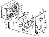
제2도는 온도조절기의 분해 투시도.2 is an exploded perspective view of the thermostat.
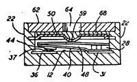
제3도는 조립된 온도 조절기의 단면도.3 is a cross-sectional view of the assembled temperature controller.
제4도는 스트립(strip)형태의 온도 조절기의 평면도.4 is a plan view of a thermostat in the form of a strip.
* 도면의 주요부분에 대한 부호의 설명* Explanation of symbols for main parts of the drawings
18 : 유전체 하우징 12 : 플로어18: dielectric housing 12: floor
14 : 플랫폼 16 : 측벽14 platform 16: side wall
18 : 곶 22 : 끝벽18: cape 22: end wall
29 : 립 30, 35 : 단자29: Lip 30, 35: Terminal
33, 38 : 핀 단자 40 : 아암33, 38: pin terminal 40: arm
59 : 딤플59: dimple
본 발명은 인쇄 회로판에 설치된 두개의 단자를 가진 패키지(package)의 단일 온도 조절기에 관한 것이다.The present invention relates to a single temperature controller in a package having two terminals mounted on a printed circuit board.
DIP(이중 인입선 패키지)는 여러가지 표준 사이즈에 유효한 전자 성분이며 PCB의 홀(hole)을 통해 판금된 형태로 받아들여진 아래로 향한 팽창 단자핀을 갖는 하우징(housing)을 포함한다. 따라서 하우징에서 칩 또는 그와 유사한 것이 회로 및 다른 성분에 연결된다.DIP (Double Leading Packages) are electronic components that are valid for several standard sizes and include a housing with downward facing expansion terminal pins received in sheet metal form through holes in the PCB. Thus, a chip or the like in the housing is connected to the circuit and other components.
기준에 의해 여기에 통합된 미합중국 특허 제4,620,175호는 4개의 단자핀을 가진 표준 DIP로써 구성된 단일 온도 조절기를 나타낸다. 패키지가 표준 DIP에 실질적으로 동일하기 때문에, PCB제조에 의해 스페이스를 잡은 어떠한 특별한 홀 또는 어떠한 특별한 조립 설비도 필요치 않다. 단자핀은 두쌍으로 작용하며, 각 쌍의 핀은 전기적으로 중복되도록 하우징 내부의 단일 내적 단부를 통해 연결된다.US Pat. No. 4,620,175, incorporated herein by reference, refers to a single temperature controller configured as a standard DIP with four terminal pins. Since the package is substantially the same as the standard DIP, no special holes or any special assembly equipment spaced by the PCB manufacturing is required. The terminal pins work in two pairs, with each pair of pins connected through a single internal end inside the housing so as to be electrically redundant.
하우징은 공동을 한정하는 플로어, 대향 병렬 측벽 및 대향 병렬 끝벽을 구성한다. 하우징은 내부 단부가 플로어의 대향 단부에서 노출되고 핀이 하우징을 통해 아래쪽으로 팽창하도록 제1 및 제2단자에 용접된다. 접촉아암은 캔틸레버 아암을 갖는 제1단자의 내부 단부에 고정되고 상기 캔털레버 아암의 자유로운 단부는 고정된 접촉을 갖으며, 제2단자의 내부 단부상의 고정 접촉을 향해 이동 가능한 것을 제외하곤 딴 데로 바이어스 된다. 중앙 딤플(dimple)을 갖는 지레 받침판은 측벽간에 고정되고 바이메탈(bimetal) 스트립은 지레 받침판과 접촉아암간에 위치된다. 바이메탈 스트립은 2개의 안정된 위피(쌍안정)을 갖는데, 제1의 안정된 위치에서, 상기 스트립은 딤플쪽으로 볼록하게 휘어지고 제1 및 제2단자간의 회로를 완성하도록 제2단자상의 접점을 향해 접촉 아암상의 접점에 바이어스된다. 예정된 온도를 초월하여 발생하는 제2의 안정된 위치에서, 바이메탈 스트립은 접촉 아암이 회로를 개방하기 위해 제2단자로부터 떨어져 작용하도록 딤플을 향해 오목하게 휘어진다. 전술한 것은 오픈 온 라이즈(open on rise) 온도 조절기를 묘사하며 크로우즈 온 라이즈(close on rise)장치는 바이메탈 스트립을 단지 전환하므로 제공될 수 있다.The housing constitutes a floor defining a cavity, opposing parallel sidewalls and opposing parallel endwalls. The housing is welded to the first and second terminals such that the inner end is exposed at the opposite end of the floor and the pin expands downward through the housing. The contact arm is fixed to the inner end of the first terminal with the cantilever arm and the free end of the cantilever arm has a fixed contact, except that it is movable toward a fixed contact on the inner end of the second terminal. Biased. A lever support plate with a central dimple is fixed between the side walls and a bimetal strip is located between the lever support plate and the contact arm. The bimetallic strip has two stable epithelium (bistable), in the first stable position, the strip bends convexly toward the dimple and contacts the contact arm towards the contact on the second terminal to complete the circuit between the first and second terminals. Biased to the contacts of the phase. In a second stable position that occurs beyond a predetermined temperature, the bimetallic strip is concavely curved toward the dimple such that the contact arm acts away from the second terminal to open the circuit. The foregoing describes an open on rise temperature controller and a close on rise device can be provided simply by switching the bimetal strip.
DIP온도 조절기는 순환 공기로부터 스위치 유도를 활성화하기에 충분한 공기 흐름내에 설치할 작정이다. 히트 싱크(heat sink) 또는 캐비넷(cabinet)의 표면 온도를 감지하기에 적당한 판에 설치된 온도 조절기를 제공하는 것이 또한 바람직하다.The DIP thermostat is intended to be installed in an air stream sufficient to activate switch induction from circulating air. It would also be desirable to provide a temperature controller mounted on a plate suitable for sensing the surface temperature of a heat sink or cabinet.
본 발명의 판 설치 온도 조절기는 제1도에 묘사된 바와 같이 TO-220 패키지와 실제로 동일하다. 상기 패키지는 두개의 단자핀과 상기 패키지 고정된 설치 브래킷(bracket)을 제외한 모든 것을 구비한다. 단자는 하우징이 용접된 편평한 스템프 부분이다. 동작성분은 종래의 기술특허에 묘사된 바와 같으나, 적시에 동작을 하도록 열을 온도조절기에 전달하는 수단이 제공된 공동에 걸쳐 고정된 설치 브래킷에 상호작용하는 커버판을 포함하며 따라서 시스템이 보호된다. 표준 TO-220 전자 패키지가 칩으로부터 떨어져 열을 전도하도록 설치 브래킷을 사용하는 반면, 본 발명의 온도조절기는 상기 온도 조절기에 근접한 표면으로부터 열을 전도하는 브래킷을 사용한다.The plate mounting thermostat of the present invention is actually identical to the TO-220 package as depicted in FIG. The package has everything except two terminal pins and the package fixed mounting bracket. The terminal is a flat stamp portion to which the housing is welded. The operating component is as described in the prior art patent, but includes a cover plate which interacts with the mounting bracket fixed over the cavity provided with means for transferring heat to the thermostat for timely operation and thus the system is protected. While the standard TO-220 electronic package uses a mounting bracket to conduct heat away from the chip, the thermostat of the present invention uses a bracket that conducts heat from a surface proximate to the thermostat.
이하 첨부된 도면을 참조하여 본원 명세서를 더욱 상세히 설명하기로 한다.Hereinafter, the present specification will be described in more detail with reference to the accompanying drawings.
제1도는 유전체 하우징(10), 핀단자(33 및 38) 및 설치 브래킷(bracket)을 포함한 표준 TO-220 전자패키지(2)를 나타낸다. 본 발명의 단극, 단투 스탭작용의 온도조절기는 동일 패키지를 점유하고 제2도에 확대 도시된다. 유전체 하우징(10)은 플로어(12), 측벽(16) 및 끝벽(22)에 의해 경계지어진 공동을 가진 박스형 구조를 형성하도록 스트레이트 인장 형태로 단자(30,35) 위에 용접된다. 양호한 물질을 리툰(Ryton) R-10과 같은 고온 플라스틱이다. 단자(30,35)는 즉시 분출하도록 플로어(12)에 삽입된 각각의 내부부분(31,36)을 갖는다. 플로어(12)는 내부부분(31)를 지나 확장한 립(29)을 구비한 립위치 부분(28)으로부터 주변 플랫폼(14)에 의해 감싸진다. 측벽(14)은 서로를 향해 확장한 두쌍의 대향곶(tongue)을 갖는 반면 끝벽(22)은 한쌍의 대향곶을 갖는다. 모든 곶은 플랫폼(14)을 지지하고 계단형 단부를 갖으며 그 기능은 이하 기술될 것이다.1 shows a standard TO-220
제2도를 참조하면, 접촉아암(40)은 스탬프되고 립(29)과 제2 또는 자유로운 단부(42)간의 반응을 위해 만들어진 제1단부 또는 베이스(41)를 가진 스프링 금속으로부터 형성된다. 조립동안 제1단부(41)는 제2단부(42)가 내부부분(36)으로부터 떨어져 바이어스되도록 내부부분(31)에 용접된 저항이다. 바이메탈 스트립(48)은 전적으로 섭씨 40도에서 150도까지인 예정된 온도에서 튀기는 종래의 디쉬(dish)소자이다. 조립동안, 스트립(48)은 아암(40)을 향한 공간에 놓여지며 따라서 상기 아암은 모든 방향에서 자유롭고 억제되지 않는다. 그후, 지레 받침판(50)은 소자(48)를 획득하도록 플랫폼(14)을 향해 놓여진다. 지레 받침판(50)은 곶(18)에 대해 반응을 위한 스캐럽(scallop, 53)을 갖는 측면 에지(52)와 곶(24)에 대해 반응을 위한 스캐럽(56)을 갖는 단부 에지를 갖는 알루미늄 형태로 스탬프된다. 또한 상기 판(50)은 공동내부로 확장된 딤플(59)을 갖는 돋운 부분(58)을 형성한다. 아암(40)및 소자(48)를 설치한 후, 지레 받침판(50)은 탭(18,24)을 열처리하므로 플랫폼(14)를 향해 유지된다. 상기는 계단형 부분(20)에 열과 압력을 인가하므로 이루어지는데 상기 계단부분(20)은 어떠한 치환 플래스틱도 곶의 가장 높은 측면에 확장하지 않는 것을 보장한다. 에폭시가 지레 받침판(50)의 상부에 인가되고 설치판(60)이 설치되며 조립체는 에폭시를 건조하기 위해 구워진다. 홀(64)은 초과 에폭시를 흡수한다. 또한, 판(60)은 회전수단을 받아들이는 중앙홀(61)을 갖는 브래킷(66)을 포함한다.Referring to FIG. 2, the
제3도는 보다 상세히 부분의 협력을 보여준다. 제2단자(35)의 내부부분(36)은 저항 용접에 의해 고정된 금판 접점(37)을 갖는 반면 접촉아암(40)의 자유로운 단부는 상기 접점에 고정된 접점(44)을 갖는다. 바이메탈 소자(48)은 단자(30,35)간의 회로가 폐쇄되도록 딤플 또는 지레 받침점(59)을 향해 볼록하게 휘어진다. 특성온도가 도달될 시에, 상기 소자는 회로가 개방되도록 반대쪽으로 휘어진 구조에 스냅(snaps)된다. 클로우즈 온 라이즈 장치는 바이메탈 스트립을 단지 전환하므로 제공될 수 있다. 밀폐 및 보유기능을 제공하도록 부가하여, 에폭시(68)는 적당한 구경측정이 유지되고 지레 받침판(50)과 설치판(60)간에 열의 이송을 보장하도록 딤플(59)을 강화한다.3 shows the cooperation of the parts in more detail. The
특히 제4도를 참조하면, 발명 스위치의 제조를 이해할 수 있다. 단자핀(33,38)은 설비가 다양한 작업 스테이션을 통해 인덱싱한 인덱싱 홀(72)을 갖춘 이송 스트립(70)에 의해 경계지어진 스탬프 금속 스트립의 부분이다. 상기 스트립은 하우징이 용접된 용접 스테이션을 통해 우선적으로 패드된 후 도시된 조립체를 산출하도록 앞서 기술된 바와 같이 부분이 조립되는 다양한 스테이션을 통해 진행된다. 각각의 온도조절기는 캐리어로부터 전단되어 사용자를 위해 튜브 또는 그 유사한 패키지된다.With particular reference to FIG. 4, the manufacture of the inventive switch can be understood.
전술한 것은 견본이고 후속하는 청구범위의 영역을 제한하지 않는다.The foregoing is a sample and does not limit the scope of the following claims.
Claims (8)
Applications Claiming Priority (2)
| Application Number | Priority Date | Filing Date | Title |
|---|---|---|---|
| US116,602 | 1987-11-02 | ||
| US07/116,602 US4795997A (en) | 1987-11-02 | 1987-11-02 | Thermostat for board mounting |
Publications (2)
| Publication Number | Publication Date |
|---|---|
| KR890008879A KR890008879A (en) | 1989-07-12 |
| KR970006441B1 true KR970006441B1 (en) | 1997-04-28 |
Family
ID=22368168
Family Applications (1)
| Application Number | Title | Priority Date | Filing Date |
|---|---|---|---|
| KR1019880014204A KR970006441B1 (en) | 1987-11-02 | 1988-10-31 | Thermostat for board mounting |
Country Status (4)
| Country | Link |
|---|---|
| US (1) | US4795997A (en) |
| EP (1) | EP0315262A1 (en) |
| JP (1) | JPH089868Y2 (en) |
| KR (1) | KR970006441B1 (en) |
Families Citing this family (20)
| Publication number | Priority date | Publication date | Assignee | Title |
|---|---|---|---|---|
| DE4409123C2 (en) * | 1994-03-17 | 1996-12-05 | Volz Abc Elektrogeraete | Device for heating liquids |
| JP2791384B2 (en) * | 1994-12-09 | 1998-08-27 | ウチヤ・サーモスタット株式会社 | thermostat |
| DE19507488C2 (en) * | 1995-03-03 | 1997-01-16 | Marcel Peter Hofsaes | Bracket for a bimetal rear derailleur and temperature monitor with a bimetal rear derailleur |
| EP0730285B1 (en) * | 1995-03-03 | 1999-10-20 | Marcel Hofsäss | Insulating housing |
| FR2766301B1 (en) * | 1997-07-17 | 1999-09-10 | Valeo Climatisation | ELECTRIC MOTOR, ESPECIALLY FOR MOTOR VEHICLES, WITH IMPROVED COOLING RADIATOR |
| GB2349508B (en) * | 1999-04-26 | 2003-04-16 | Otter Controls Ltd | Improvements relating to thermally-responsive controls |
| US6330157B1 (en) * | 1999-12-21 | 2001-12-11 | International Business Machines Corporation | Variable thermal exchanger and method thereof |
| US6771159B2 (en) * | 2001-11-08 | 2004-08-03 | Airpax Corporation L.L.C. | Contact spring for miniature thermostat |
| ITMI20061322A1 (en) | 2006-07-07 | 2008-01-08 | Morsettitalia Spa | BRIDGE ISOLATED PARTICULARLY FOR TERMINALS OF ELECTRIC PANELS |
| ITMI20070186A1 (en) * | 2007-02-05 | 2008-08-06 | Morsettitalia Spa | PROCEDURE FOR THE PRODUCTION OF CONTACT ELEMENTS OF LAMINATED FURNITURE AND CONTACT ELEMENTS COMPLETED. |
| EP1953869B1 (en) * | 2007-02-05 | 2014-07-30 | Morsettitalia S.p.A. | Terminal block with jaw part for engagement with the flat pin of movable electric contacts |
| ITMI20071390A1 (en) * | 2007-07-12 | 2009-01-13 | Morsettitalia Spa | TIGHTENING ELEMENT WITH L-SHAPED CONDUCTOR ELEMENT FOR THE CONNECTION OF ELECTRIC WIRES |
| FR2914138B1 (en) * | 2007-03-23 | 2010-09-10 | Cotherm Sa | DEVICE FOR SECURING AND CONTROLLING AN ELECTRO-DOMESTIC APPARATUS. |
| FR2925216B1 (en) * | 2007-12-18 | 2010-04-23 | Abb France | OVERVOLTAGE PROTECTION DEVICE HAVING A DISCONNECTION AUXILIARY |
| WO2009102321A1 (en) * | 2008-02-12 | 2009-08-20 | Hewlett-Packard Development Company, L.P. | Computing devices having fail-safe mechanical shut-off switch |
| ITMI20080673A1 (en) * | 2008-04-15 | 2009-10-16 | Morsettitalia Spa | ELASTIC ELEMENT FOR THE HOLDING OF ELECTRIC WIRES AND CLAMP INCLUDING THIS ELASTIC ELEMENT |
| ITMI20080674A1 (en) * | 2008-04-15 | 2009-10-16 | Morsettitalia Spa | MULTILAYER CONDUCTOR BODY AND PROCEDURE FOR THE PRODUCTION OF THE SAME |
| DE102009039948A1 (en) * | 2009-08-27 | 2011-03-03 | Hofsaess, Marcel P. | Temperature-dependent switch |
| US20160277017A1 (en) * | 2011-09-13 | 2016-09-22 | Fsp Technology Inc. | Snubber circuit |
| DE102012111566A1 (en) * | 2012-11-29 | 2014-06-05 | Eaton Electrical Ip Gmbh & Co. Kg | Tripping device for circuit breaker |
Family Cites Families (7)
| Publication number | Priority date | Publication date | Assignee | Title |
|---|---|---|---|---|
| GB1071161A (en) * | 1962-10-09 | 1967-06-07 | Radiation Ltd | Improvements in or relating to mounting arrangements for thermally responsive devices |
| US3322918A (en) * | 1965-10-14 | 1967-05-30 | George Ulanet Co | Surface sensing bimetal thermostatic switch |
| AT300407B (en) * | 1970-10-28 | 1972-07-25 | Richard Fonovits Kommanditgese | Electrical temperature fuse and procedure for adjusting the same |
| US4045761A (en) * | 1976-02-09 | 1977-08-30 | Jenoff, Incorporated | Mounting bracket for a heat detector switch |
| US4308517A (en) * | 1980-12-03 | 1981-12-29 | Jenoff, Incorporated | Heat sensing apparatus |
| DE8101980U1 (en) * | 1981-01-27 | 1981-06-25 | Siemens AG, 1000 Berlin und 8000 München | Thermal switch |
| US4620175A (en) * | 1985-10-11 | 1986-10-28 | North American Philips Corporation | Simple thermostat for dip mounting |
-
1987
- 1987-11-02 US US07/116,602 patent/US4795997A/en not_active Expired - Fee Related
-
1988
- 1988-10-28 EP EP88202410A patent/EP0315262A1/en not_active Withdrawn
- 1988-10-31 JP JP1988141246U patent/JPH089868Y2/en not_active Expired - Lifetime
- 1988-10-31 KR KR1019880014204A patent/KR970006441B1/en active IP Right Grant
Also Published As
| Publication number | Publication date |
|---|---|
| JPH089868Y2 (en) | 1996-03-21 |
| US4795997A (en) | 1989-01-03 |
| EP0315262A1 (en) | 1989-05-10 |
| KR890008879A (en) | 1989-07-12 |
| JPH0175946U (en) | 1989-05-23 |
Similar Documents
| Publication | Publication Date | Title |
|---|---|---|
| KR970006441B1 (en) | Thermostat for board mounting | |
| CA1204522A (en) | Heat dissipator for semiconductor devices | |
| US4258349A (en) | Double-pole rocker switch with thermal protection | |
| US4215361A (en) | Winged self-fastened heat sinks for semiconductor devices | |
| JP3725296B2 (en) | Temperature sensor with measuring resistor | |
| JP2777042B2 (en) | Thermo switch | |
| US4620175A (en) | Simple thermostat for dip mounting | |
| US2820870A (en) | Thermostatic switch | |
| US6088228A (en) | Protective enclosure for a multi-chip module | |
| JPH0644600B2 (en) | Semiconductor assembly unit | |
| JP4279367B2 (en) | Thermal switch | |
| EP0128978B1 (en) | Thermostat | |
| US20220262564A1 (en) | Capacitor | |
| US4913285A (en) | Water-and-dust-proof push-button switch housing dummy terminal for air venting | |
| US4754252A (en) | Thermostatic switch with improved cap disc assembly | |
| JPH03171577A (en) | Socket for chip carrier | |
| CA1146283A (en) | Arrangement for mounting dual-in-line packaged integrated circuits to thick/thin film circuits | |
| US4101861A (en) | Thermostatic switch and method of assembly | |
| US4492946A (en) | Edge-actuated thermostat | |
| US6771159B2 (en) | Contact spring for miniature thermostat | |
| US6483418B1 (en) | Creep acting miniature thermostatic electrical switch and thermostatic member used therewith | |
| JP2554409B2 (en) | Heat transfer member and electrical component assembly including the heat transfer member | |
| US4902999A (en) | Enclosed bimetal circuit breaker | |
| KR20070109953A (en) | Thermally responsive electrical switch | |
| US4079348A (en) | Thermally responsive electrical switch |
Legal Events
| Date | Code | Title | Description |
|---|---|---|---|
| A201 | Request for examination | ||
| G160 | Decision to publish patent application | ||
| E701 | Decision to grant or registration of patent right | ||
| NORF | Unpaid initial registration fee |