KR960010371B1 - Filter for the separation of solids from heat gaseous of liquid media - Google Patents
Filter for the separation of solids from heat gaseous of liquid media Download PDFInfo
- Publication number
- KR960010371B1 KR960010371B1 KR1019890007669A KR890007669A KR960010371B1 KR 960010371 B1 KR960010371 B1 KR 960010371B1 KR 1019890007669 A KR1019890007669 A KR 1019890007669A KR 890007669 A KR890007669 A KR 890007669A KR 960010371 B1 KR960010371 B1 KR 960010371B1
- Authority
- KR
- South Korea
- Prior art keywords
- filter
- carrier
- carrier material
- cover layer
- filling material
- Prior art date
Links
- 239000007788 liquid Substances 0.000 title claims description 15
- 238000000926 separation method Methods 0.000 title description 6
- 239000007787 solid Substances 0.000 title 1
- 239000000463 material Substances 0.000 claims description 79
- 239000012876 carrier material Substances 0.000 claims description 60
- 238000011049 filling Methods 0.000 claims description 27
- 239000011148 porous material Substances 0.000 claims description 20
- 239000002245 particle Substances 0.000 claims description 19
- 239000000945 filler Substances 0.000 claims description 18
- 238000000034 method Methods 0.000 claims description 15
- 239000000919 ceramic Substances 0.000 claims description 14
- 238000001914 filtration Methods 0.000 claims description 13
- 239000000203 mixture Substances 0.000 claims description 13
- 238000010304 firing Methods 0.000 claims description 7
- 229920002472 Starch Polymers 0.000 claims description 6
- 238000004140 cleaning Methods 0.000 claims description 6
- 239000008107 starch Substances 0.000 claims description 6
- 235000019698 starch Nutrition 0.000 claims description 6
- 239000000839 emulsion Substances 0.000 claims description 5
- 239000000843 powder Substances 0.000 claims description 5
- XLYOFNOQVPJJNP-UHFFFAOYSA-N water Substances O XLYOFNOQVPJJNP-UHFFFAOYSA-N 0.000 claims description 5
- 239000000567 combustion gas Substances 0.000 claims description 4
- 239000010419 fine particle Substances 0.000 claims description 4
- 238000004519 manufacturing process Methods 0.000 claims description 4
- 229910052751 metal Inorganic materials 0.000 claims description 4
- 239000002184 metal Substances 0.000 claims description 4
- 230000003511 endothelial effect Effects 0.000 claims description 3
- 238000009434 installation Methods 0.000 claims description 3
- 239000005995 Aluminium silicate Substances 0.000 claims description 2
- CDBYLPFSWZWCQE-UHFFFAOYSA-L Sodium Carbonate Chemical group [Na+].[Na+].[O-]C([O-])=O CDBYLPFSWZWCQE-UHFFFAOYSA-L 0.000 claims description 2
- 235000012211 aluminium silicate Nutrition 0.000 claims description 2
- 238000001704 evaporation Methods 0.000 claims description 2
- 239000010433 feldspar Substances 0.000 claims description 2
- 239000011521 glass Substances 0.000 claims description 2
- NLYAJNPCOHFWQQ-UHFFFAOYSA-N kaolin Chemical compound O.O.O=[Al]O[Si](=O)O[Si](=O)O[Al]=O NLYAJNPCOHFWQQ-UHFFFAOYSA-N 0.000 claims description 2
- 150000002739 metals Chemical class 0.000 claims description 2
- 235000019353 potassium silicate Nutrition 0.000 claims description 2
- NTHWMYGWWRZVTN-UHFFFAOYSA-N sodium silicate Chemical compound [Na+].[Na+].[O-][Si]([O-])=O NTHWMYGWWRZVTN-UHFFFAOYSA-N 0.000 claims description 2
- 239000011343 solid material Substances 0.000 claims description 2
- 238000005507 spraying Methods 0.000 claims description 2
- 241001494479 Pecora Species 0.000 claims 1
- 230000006835 compression Effects 0.000 claims 1
- 238000007906 compression Methods 0.000 claims 1
- 238000001816 cooling Methods 0.000 claims 1
- 239000001177 diphosphate Substances 0.000 claims 1
- XPPKVPWEQAFLFU-UHFFFAOYSA-J diphosphate(4-) Chemical compound [O-]P([O-])(=O)OP([O-])([O-])=O XPPKVPWEQAFLFU-UHFFFAOYSA-J 0.000 claims 1
- 235000011180 diphosphates Nutrition 0.000 claims 1
- 238000005259 measurement Methods 0.000 claims 1
- 239000013618 particulate matter Substances 0.000 claims 1
- 230000009182 swimming Effects 0.000 claims 1
- XLOMVQKBTHCTTD-UHFFFAOYSA-N Zinc monoxide Chemical compound [Zn]=O XLOMVQKBTHCTTD-UHFFFAOYSA-N 0.000 description 6
- 239000007789 gas Substances 0.000 description 6
- 238000007789 sealing Methods 0.000 description 6
- 239000000853 adhesive Substances 0.000 description 4
- 230000001070 adhesive effect Effects 0.000 description 4
- 239000003779 heat-resistant material Substances 0.000 description 4
- 210000001519 tissue Anatomy 0.000 description 4
- 229910018072 Al 2 O 3 Inorganic materials 0.000 description 3
- 229910004298 SiO 2 Inorganic materials 0.000 description 3
- 210000003298 dental enamel Anatomy 0.000 description 3
- 239000000725 suspension Substances 0.000 description 3
- 239000011787 zinc oxide Substances 0.000 description 3
- 229920000049 Carbon (fiber) Polymers 0.000 description 2
- 230000015572 biosynthetic process Effects 0.000 description 2
- 239000004917 carbon fiber Substances 0.000 description 2
- 239000011248 coating agent Substances 0.000 description 2
- 238000000576 coating method Methods 0.000 description 2
- 230000001419 dependent effect Effects 0.000 description 2
- 210000003038 endothelium Anatomy 0.000 description 2
- 230000003628 erosive effect Effects 0.000 description 2
- 238000010438 heat treatment Methods 0.000 description 2
- TWNQGVIAIRXVLR-UHFFFAOYSA-N oxo(oxoalumanyloxy)alumane Chemical compound O=[Al]O[Al]=O TWNQGVIAIRXVLR-UHFFFAOYSA-N 0.000 description 2
- 238000003825 pressing Methods 0.000 description 2
- 239000000126 substance Substances 0.000 description 2
- 235000002918 Fraxinus excelsior Nutrition 0.000 description 1
- VYPSYNLAJGMNEJ-UHFFFAOYSA-N Silicium dioxide Chemical compound O=[Si]=O VYPSYNLAJGMNEJ-UHFFFAOYSA-N 0.000 description 1
- 238000005273 aeration Methods 0.000 description 1
- 239000002956 ash Substances 0.000 description 1
- 238000011001 backwashing Methods 0.000 description 1
- 238000007664 blowing Methods 0.000 description 1
- QXJJQWWVWRCVQT-UHFFFAOYSA-K calcium;sodium;phosphate Chemical compound [Na+].[Ca+2].[O-]P([O-])([O-])=O QXJJQWWVWRCVQT-UHFFFAOYSA-K 0.000 description 1
- 229910010293 ceramic material Inorganic materials 0.000 description 1
- 239000004927 clay Substances 0.000 description 1
- 238000003181 co-melting Methods 0.000 description 1
- 239000011362 coarse particle Substances 0.000 description 1
- 238000002485 combustion reaction Methods 0.000 description 1
- 150000001875 compounds Chemical class 0.000 description 1
- 238000011109 contamination Methods 0.000 description 1
- 230000007812 deficiency Effects 0.000 description 1
- 239000000428 dust Substances 0.000 description 1
- 230000000694 effects Effects 0.000 description 1
- 238000005265 energy consumption Methods 0.000 description 1
- 230000008020 evaporation Effects 0.000 description 1
- 239000004744 fabric Substances 0.000 description 1
- 239000000835 fiber Substances 0.000 description 1
- 238000003780 insertion Methods 0.000 description 1
- 230000037431 insertion Effects 0.000 description 1
- JEIPFZHSYJVQDO-UHFFFAOYSA-N iron(III) oxide Inorganic materials O=[Fe]O[Fe]=O JEIPFZHSYJVQDO-UHFFFAOYSA-N 0.000 description 1
- 230000007774 longterm Effects 0.000 description 1
- VNWKTOKETHGBQD-UHFFFAOYSA-N methane Chemical compound C VNWKTOKETHGBQD-UHFFFAOYSA-N 0.000 description 1
- 239000011859 microparticle Substances 0.000 description 1
- 210000000496 pancreas Anatomy 0.000 description 1
- 239000002994 raw material Substances 0.000 description 1
- 238000010992 reflux Methods 0.000 description 1
- 229920005989 resin Polymers 0.000 description 1
- 239000011347 resin Substances 0.000 description 1
- 229910052814 silicon oxide Inorganic materials 0.000 description 1
- 238000005245 sintering Methods 0.000 description 1
- 229920003002 synthetic resin Polymers 0.000 description 1
- 239000000057 synthetic resin Substances 0.000 description 1
- 239000004753 textile Substances 0.000 description 1
Images


Classifications
-
- B—PERFORMING OPERATIONS; TRANSPORTING
- B01—PHYSICAL OR CHEMICAL PROCESSES OR APPARATUS IN GENERAL
- B01D—SEPARATION
- B01D67/00—Processes specially adapted for manufacturing semi-permeable membranes for separation processes or apparatus
- B01D67/0039—Inorganic membrane manufacture
- B01D67/0041—Inorganic membrane manufacture by agglomeration of particles in the dry state
- B01D67/00411—Inorganic membrane manufacture by agglomeration of particles in the dry state by sintering
-
- B—PERFORMING OPERATIONS; TRANSPORTING
- B01—PHYSICAL OR CHEMICAL PROCESSES OR APPARATUS IN GENERAL
- B01D—SEPARATION
- B01D29/00—Filters with filtering elements stationary during filtration, e.g. pressure or suction filters, not covered by groups B01D24/00 - B01D27/00; Filtering elements therefor
- B01D29/11—Filters with filtering elements stationary during filtration, e.g. pressure or suction filters, not covered by groups B01D24/00 - B01D27/00; Filtering elements therefor with bag, cage, hose, tube, sleeve or like filtering elements
- B01D29/111—Making filtering elements
-
- B—PERFORMING OPERATIONS; TRANSPORTING
- B01—PHYSICAL OR CHEMICAL PROCESSES OR APPARATUS IN GENERAL
- B01D—SEPARATION
- B01D29/00—Filters with filtering elements stationary during filtration, e.g. pressure or suction filters, not covered by groups B01D24/00 - B01D27/00; Filtering elements therefor
- B01D29/11—Filters with filtering elements stationary during filtration, e.g. pressure or suction filters, not covered by groups B01D24/00 - B01D27/00; Filtering elements therefor with bag, cage, hose, tube, sleeve or like filtering elements
- B01D29/31—Self-supporting filtering elements
- B01D29/33—Self-supporting filtering elements arranged for inward flow filtration
-
- B—PERFORMING OPERATIONS; TRANSPORTING
- B01—PHYSICAL OR CHEMICAL PROCESSES OR APPARATUS IN GENERAL
- B01D—SEPARATION
- B01D29/00—Filters with filtering elements stationary during filtration, e.g. pressure or suction filters, not covered by groups B01D24/00 - B01D27/00; Filtering elements therefor
- B01D29/50—Filters with filtering elements stationary during filtration, e.g. pressure or suction filters, not covered by groups B01D24/00 - B01D27/00; Filtering elements therefor with multiple filtering elements, characterised by their mutual disposition
- B01D29/52—Filters with filtering elements stationary during filtration, e.g. pressure or suction filters, not covered by groups B01D24/00 - B01D27/00; Filtering elements therefor with multiple filtering elements, characterised by their mutual disposition in parallel connection
-
- B—PERFORMING OPERATIONS; TRANSPORTING
- B01—PHYSICAL OR CHEMICAL PROCESSES OR APPARATUS IN GENERAL
- B01D—SEPARATION
- B01D37/00—Processes of filtration
- B01D37/02—Precoating the filter medium; Addition of filter aids to the liquid being filtered
-
- B—PERFORMING OPERATIONS; TRANSPORTING
- B01—PHYSICAL OR CHEMICAL PROCESSES OR APPARATUS IN GENERAL
- B01D—SEPARATION
- B01D39/00—Filtering material for liquid or gaseous fluids
- B01D39/14—Other self-supporting filtering material ; Other filtering material
- B01D39/20—Other self-supporting filtering material ; Other filtering material of inorganic material, e.g. asbestos paper, metallic filtering material of non-woven wires
- B01D39/2068—Other inorganic materials, e.g. ceramics
- B01D39/2072—Other inorganic materials, e.g. ceramics the material being particulate or granular
- B01D39/2075—Other inorganic materials, e.g. ceramics the material being particulate or granular sintered or bonded by inorganic agents
-
- B—PERFORMING OPERATIONS; TRANSPORTING
- B01—PHYSICAL OR CHEMICAL PROCESSES OR APPARATUS IN GENERAL
- B01D—SEPARATION
- B01D46/00—Filters or filtering processes specially modified for separating dispersed particles from gases or vapours
- B01D46/24—Particle separators, e.g. dust precipitators, using rigid hollow filter bodies
-
- B—PERFORMING OPERATIONS; TRANSPORTING
- B01—PHYSICAL OR CHEMICAL PROCESSES OR APPARATUS IN GENERAL
- B01D—SEPARATION
- B01D71/00—Semi-permeable membranes for separation processes or apparatus characterised by the material; Manufacturing processes specially adapted therefor
- B01D71/02—Inorganic material
- B01D71/0213—Silicon
-
- C—CHEMISTRY; METALLURGY
- C04—CEMENTS; CONCRETE; ARTIFICIAL STONE; CERAMICS; REFRACTORIES
- C04B—LIME, MAGNESIA; SLAG; CEMENTS; COMPOSITIONS THEREOF, e.g. MORTARS, CONCRETE OR LIKE BUILDING MATERIALS; ARTIFICIAL STONE; CERAMICS; REFRACTORIES; TREATMENT OF NATURAL STONE
- C04B41/00—After-treatment of mortars, concrete, artificial stone or ceramics; Treatment of natural stone
- C04B41/009—After-treatment of mortars, concrete, artificial stone or ceramics; Treatment of natural stone characterised by the material treated
-
- C—CHEMISTRY; METALLURGY
- C04—CEMENTS; CONCRETE; ARTIFICIAL STONE; CERAMICS; REFRACTORIES
- C04B—LIME, MAGNESIA; SLAG; CEMENTS; COMPOSITIONS THEREOF, e.g. MORTARS, CONCRETE OR LIKE BUILDING MATERIALS; ARTIFICIAL STONE; CERAMICS; REFRACTORIES; TREATMENT OF NATURAL STONE
- C04B41/00—After-treatment of mortars, concrete, artificial stone or ceramics; Treatment of natural stone
- C04B41/45—Coating or impregnating, e.g. injection in masonry, partial coating of green or fired ceramics, organic coating compositions for adhering together two concrete elements
- C04B41/50—Coating or impregnating, e.g. injection in masonry, partial coating of green or fired ceramics, organic coating compositions for adhering together two concrete elements with inorganic materials
- C04B41/5025—Coating or impregnating, e.g. injection in masonry, partial coating of green or fired ceramics, organic coating compositions for adhering together two concrete elements with inorganic materials with ceramic materials
-
- C—CHEMISTRY; METALLURGY
- C04—CEMENTS; CONCRETE; ARTIFICIAL STONE; CERAMICS; REFRACTORIES
- C04B—LIME, MAGNESIA; SLAG; CEMENTS; COMPOSITIONS THEREOF, e.g. MORTARS, CONCRETE OR LIKE BUILDING MATERIALS; ARTIFICIAL STONE; CERAMICS; REFRACTORIES; TREATMENT OF NATURAL STONE
- C04B41/00—After-treatment of mortars, concrete, artificial stone or ceramics; Treatment of natural stone
- C04B41/45—Coating or impregnating, e.g. injection in masonry, partial coating of green or fired ceramics, organic coating compositions for adhering together two concrete elements
- C04B41/50—Coating or impregnating, e.g. injection in masonry, partial coating of green or fired ceramics, organic coating compositions for adhering together two concrete elements with inorganic materials
- C04B41/5076—Coating or impregnating, e.g. injection in masonry, partial coating of green or fired ceramics, organic coating compositions for adhering together two concrete elements with inorganic materials with masses bonded by inorganic cements
- C04B41/5089—Silica sols, alkyl, ammonium or alkali metal silicate cements
-
- C—CHEMISTRY; METALLURGY
- C04—CEMENTS; CONCRETE; ARTIFICIAL STONE; CERAMICS; REFRACTORIES
- C04B—LIME, MAGNESIA; SLAG; CEMENTS; COMPOSITIONS THEREOF, e.g. MORTARS, CONCRETE OR LIKE BUILDING MATERIALS; ARTIFICIAL STONE; CERAMICS; REFRACTORIES; TREATMENT OF NATURAL STONE
- C04B41/00—After-treatment of mortars, concrete, artificial stone or ceramics; Treatment of natural stone
- C04B41/80—After-treatment of mortars, concrete, artificial stone or ceramics; Treatment of natural stone of only ceramics
- C04B41/81—Coating or impregnation
- C04B41/85—Coating or impregnation with inorganic materials
- C04B41/87—Ceramics
-
- B—PERFORMING OPERATIONS; TRANSPORTING
- B01—PHYSICAL OR CHEMICAL PROCESSES OR APPARATUS IN GENERAL
- B01D—SEPARATION
- B01D2201/00—Details relating to filtering apparatus
- B01D2201/04—Supports for the filtering elements
- B01D2201/043—Filter tubes connected to plates
- B01D2201/0453—Filter tubes connected to plates positioned between at least two plates
-
- B—PERFORMING OPERATIONS; TRANSPORTING
- B01—PHYSICAL OR CHEMICAL PROCESSES OR APPARATUS IN GENERAL
- B01D—SEPARATION
- B01D2239/00—Aspects relating to filtering material for liquid or gaseous fluids
- B01D2239/04—Additives and treatments of the filtering material
- B01D2239/0471—Surface coating material
-
- B—PERFORMING OPERATIONS; TRANSPORTING
- B01—PHYSICAL OR CHEMICAL PROCESSES OR APPARATUS IN GENERAL
- B01D—SEPARATION
- B01D2273/00—Operation of filters specially adapted for separating dispersed particles from gases or vapours
- B01D2273/20—High temperature filtration
-
- B—PERFORMING OPERATIONS; TRANSPORTING
- B01—PHYSICAL OR CHEMICAL PROCESSES OR APPARATUS IN GENERAL
- B01D—SEPARATION
- B01D2323/00—Details relating to membrane preparation
- B01D2323/12—Specific ratios of components used
-
- C—CHEMISTRY; METALLURGY
- C04—CEMENTS; CONCRETE; ARTIFICIAL STONE; CERAMICS; REFRACTORIES
- C04B—LIME, MAGNESIA; SLAG; CEMENTS; COMPOSITIONS THEREOF, e.g. MORTARS, CONCRETE OR LIKE BUILDING MATERIALS; ARTIFICIAL STONE; CERAMICS; REFRACTORIES; TREATMENT OF NATURAL STONE
- C04B2111/00—Mortars, concrete or artificial stone or mixtures to prepare them, characterised by specific function, property or use
- C04B2111/00474—Uses not provided for elsewhere in C04B2111/00
- C04B2111/00793—Uses not provided for elsewhere in C04B2111/00 as filters or diaphragms
Abstract
내용없음No content
Description
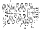
제 1 도는 원통형의 튜브들로서 만들어진 휠터요소의 측면도,1 is a side view of a filter element made as cylindrical tubes,
제 2 도는 제 1 도에서의 평면 II-II에서의 휠터요소의 단면도,2 is a cross-sectional view of the filter element in plane II-II in FIG. 1,
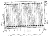
제 3 도는 박판 묶음으로서 만들어진 휠터요소의 측면도,3 is a side view of a filter element made as a bundle of sheets,
제 4 도는 제 3 도에서 평면 IV-IV에서 휠터요소의 단면도,4 is a cross-sectional view of the filter element in plane IV-IV in FIG. 3,
제 5 도는 덮개층을 형성하고 있으며, 예를 들면 동일한 직경의 다수의 구들을 가지는 제 1 도 또는 제 3 도에 의한 절단된 휠터요소의 절단편의 확대 평면도,5 shows an enlarged plan view of the cut piece of the cut filter element, according to FIG. 1 or 3, which forms a covering layer, for example having a plurality of spheres of the same diameter,
제 6 도는 제 5 도와 유사하나 그러나 예를 들면 상이한 직경의 구들을 가지는 확대평면도,FIG. 6 is an enlarged plan view similar to FIG. 5 but with, for example, spheres of different diameters,
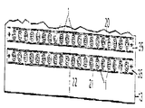
제 7 도는 절단편 III에 따르는 휠터요소의 덮개층에 쌓여있는 구들의 열과 그리고 담체재료안에 넣어져 있는 분말 입자들을 가지는 휠터요소의 덮개층의 범위에서의 휠터요소의 단면도,7 shows a cross-sectional view of the filter element in the range of the cover layer of the filter element with rows of spheres stacked on the cover layer of the filter element according to the cut piece III and powder particles encased in the carrier material,
제 8 도는 다수의 휠터양초형상부로부터 되어 있는 하나의 휠터요소를 가지는 휠터케이싱의 종방향 중앙단면도,8 is a longitudinal central cross-sectional view of a wheeler casing having one wheeler element formed from a plurality of wheeler candle shapes;
제 9 도는 제 1 도에서 평편 II-II에 있는 평행하게 배열된 2개의 휠터요소를 가지는 휠터케이싱의 횡단면도,FIG. 9 is a cross sectional view of the wheel casing having two wheel elements arranged in parallel in plane II-II in FIG.
제10도는 휠터양초형상부로서 만들어진 휠터요소와 그리고 이 휠터양초형상부를 그것에 지지하고 있는 지지수단의 확대단면도,10 is an enlarged cross-sectional view of a filter element made as a filter candle element and a supporting means for supporting the filter candle element therein;
제11도는 휠터양초형상부들 그의 지지부에 지지하고 있는 관후랜지를 가지는 휠터양초형상의 두부의 확대된 종방향 중앙단면도, 그리고FIG. 11 is an enlarged longitudinal central cross-sectional view of the head of the filter-shaped candle with the tube flange supporting the filter-shaped candle shaped parts thereof, and FIG.
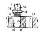
제12도는 휠터양초형상부를 그의 지지부에 지지하고 있는 원형보울트를 가지는 휠터양초형상부의 족부의 확대된 종방향 중앙단면도임.FIG. 12 is an enlarged longitudinal central cross-sectional view of a foot of a Wheeler Candle shape having a circular bolt supporting the Wheeler Candle shape at its support.
* 도면의 주요부분에 대한 부호의 설명* Explanation of symbols for main parts of the drawings
1 : 휠터요소2 : 담체1: filter element 2: carrier
11 : 덮개층17 : 배출샤프트11: cover layer 17: discharge shaft
29 : 원형보울트34 : 나선형스프링29: round bolt 34: spiral spring
이 발명은 투과성이고 형상이 안정하여 큰 구멍들을 가지고 있는 담체재료, 즉 담체로 되어 있으며 120 내지 800℃ 사이의 온도범위에서 더운 연소개스로부터의 더운, 기체형상의 혹은 액상의 매질 특히 먼지입자들로부터 고체재료 미랍자를 분리하기 위한 휠터에 관한 것이며, 여기서 담체재료는 내열성으로 만들어져 있으며 그리고 유리, 세라믹, 금속 또는 이들의 결합물과 같이 침식되지 않는 재료의 성분들을 가지며, 그리고 그 휠터의 경우에 담체재료는 이 재료의 내열성의 입자들의 내부의, 부분적인 결합에 의하여 제조할 수 있으며, 역시 담체재료는 적용내용 및 주어진 체적에 적합한 구조 또는 공간형태를 가진다.This invention is a carrier material which is permeable and stable in shape, having large pores, i.e., a carrier, from a hot, gaseous or liquid medium, especially dust particles, from a hot combustion gas in the temperature range between 120 and 800 ° C. Relates to a filter for separating solid material microparticles, wherein the carrier material is made of heat resistance and has components of a material that does not erode, such as glass, ceramics, metals or combinations thereof, and in the case of the filter Can be prepared by partial bonding of the interior of the heat resistant particles of this material, and the carrier material also has a structure or space shape suitable for the application and given volume.
개스형상의 또는 액상의 매질로부터 입자들의 분리를 위하여 휠터를 사용하는 것과 그리고 이들의 사용분야 여하에 따라서 이들을 직물의, 탄소섬유의 휠터, 모전휠터, 종이휠터, 합성수지휠터, 금속- 또는 세라믹휠터로서 만드는 것은 일반적으로 공지되어 있다. 직물의-, 모전의-, 종이의- 그리고 합성수지휠터가 약 150℃까지의 낮은 온도범위에서 설치되어지는 반면에 금속- 및 세라믹 휠터는 더 높은 온도 즉 약 800℃까지 카버할 수가 있으며, 그 결과로 후자의 휠터들은 역시 가열시설의 연산개스 범위에 설치하는 것이 적합하여진다. 이것은 특히 그래서 한편으로는 청전된 개스의 높은 열함량이 그 다음에 또 다른 조처가 없이 이용되어질 수 있고, 다른 한편으로는 이 연소개스가 환경의 더 적은 부담을 일으키기 때문에 환경을 오염시키는 방출량의 감소가 증가함에 따라 250℃ 이상의 온도를 가지는 더운 개스의 여과가 의미에 있어서 증가할때에 원하여진다.The use of a filter for the separation of particles from a gaseous or liquid medium and, depending on their application, as a textile, a carbon fiber filter, a ceramic filter, a paper filter, a resin filter, a metal- or ceramic filter. Making is generally known. Woven-, pre-, paper- and synthetic filter filters are installed at lower temperature ranges of up to about 150 ° C, while metal- and ceramic filters can cover higher temperatures, or about 800 ° C. The latter filter is also suitable for installation in the operating gas range of the heating plant. This is especially so on the one hand that the high heat content of the cleaned gas can then be used without further action, and on the other hand the reduction of emissions polluting the environment because this combustion gas causes less burden on the environment. As is increased, it is desired when the filtration of hot gases with temperatures above 250 ° C. increases in meaning.
휠터에 대한 전술한 재료들의 사용은 그 사이에 유리-, 세라믹- 및 탄소섬유가 췌성의 결과로 파단 민감성이 있으며 금속와이어들 내지 금속직물의 경우에는 미세한 분진들의 경우에 충분한 휠터작용을 얻기 위해서 와이어들 사이의 중간 공간이 너무 크다는 것을 보여왔다. 특별한 청정조처에 의하여도 역시 더 이상 밖으로 풀려나와질 수가 없으며 이것으로 인하여 드디어는 휠터의 폐쇄를 야기시키기 때문에 처음에는 좋은 분리작용이 계속해서 악화하므로 소결재료, 다공성의 작은 구멍의 세라믹 재료등과 같은 그러한 내열성 재료의 사상은 역시 비교적 적다는 것이 덧붙여진다.The use of the aforementioned materials for the filter results in that glass-, ceramic- and carbon fibers are susceptible to breakage as a result of the pancreas and that the wires can be obtained to obtain sufficient filter action in the case of fine dusts in the case of metal wires or metal fabrics. It has been shown that the middle space between them is too large. Special cleansing measures can also not be released anymore, which finally causes the closure of the filter, so that at first the good separation continues to deteriorate, such as sintered material, porous microporous ceramic material, etc. It is added that the idea of such heat resistant materials is also relatively small.
소위 고온 범위에서의 사용을 위한 휠터의 경우에 그러한 것이 설치되어 그의 휠터요소들은 다중으로 점토 내지 세라믹으로부터 되어 있으며 그리고 이것은 단순화를 위하여 휠터양초형상부의 형태로 되어 있는 원통형의 튜브들로서 만들어져 있다. 일측에 개방되게 만들어져 있는 상기의 휠터양초형상부들은 휠터에 대한 케이싱내에 있는 지지부들 사이에 설치되어 있으며, 그리고 거기서 여과하고자 하는 매질이 휠터양초형상부의 외피를 통하여 그의 내부로 침입하며 그리고 이 매질은 휠터양초형상부의 일단에 있는 개구를 통하여 내부를 다시 떠나도록 그렇게 고정되어 있다. 휠터양초형상부의 상기의 개구는 여과된 매질을 위한 하나의 고공간으로 접하며 상기의 매질은 휠터의 출구 접합부를 거쳐서 장기 공간을 떠난다. 지지부들에 고정된 휠터양초형상부는 이 지지부들에 단단히 접합되어 있으며, 그리고 매질의 유동에 의한 부하들에 그리고 매질의 역유동에 의한 상기 양초형상부의 청정작업 동안의 부하들에 응할 수가 없으며, 이것으로 인하여 특히 휠터양초형상부의 목부분에서 파손이 방지되어질 수 없다(DE-PS 30 17 851 비교).In the case of a filter for use in the so-called high temperature range, it is installed so that the filter elements are made from clay or ceramic in multiples and this is made as cylindrical tubes in the form of a filter candle for simplicity. The above-described filler candle-shaped parts which are made open on one side are installed between the supports in the casing for the filter, where the medium to be filtered enters its interior through the outer shell of the filter-canter candle and the medium It is so secured that it leaves the interior again through an opening at one end of the filter candles. The opening of the filter candle candle is in contact with one high space for the filtered medium, which leaves the long term space through the outlet junction of the filter. The filler candle-shaped fixed to the supports is firmly bonded to these supports and cannot respond to the loads by the flow of the medium and the loads during the clean operation of the candle-shaped by the backflow of the medium, which As a result, breakage cannot be prevented, especially in the neck of the filter candles (comp. DE-PS 30 17 851).
휠터양초형상부에서의 특별한 그러한 손상들을 피하기 위하여 상기한 종류의 휠터양초형상부는 지지부들에 진동하면서 고정되어 있다. 그때그때의 휠터양초형상부의 상기의 진동하고 있는 고정은 한편으로는 청정공간을 휠터 공간으로부터 분리하고 있는 지지부가 구멍판으로서 만들어져 있으며 여기서 구멍들은 이들이 청정공간쪽으로가 휠터공간쪽으로 보다 더 큰 개구횡단면을 가지도록 그렇게 형성되어 있도록 하는 방법으로 가능하다. 휠터양초형상부는 다시금 청정공간에 향하고 있는 이 양초형상부의 단부에 하나의 후랜지 형상의 칼라가 설치되어 있으며, 이 칼라를 가지고는 상기의 휠터양초형상부는 지지부에 있는 구멍의 내부를 향하여 뻗쳐 있는 원형돌기위에 지지된다.In order to avoid special such damages in the filter candles, the filter candles of the kind mentioned above are fixed while vibrating to the supports. The oscillating fixation of the then-illustrated candle-shaped part is then made, on the one hand, as a hole plate which separates the clean space from the filter space, where the holes have a larger opening transverse section towards the clean space than toward the filter space. It is possible in such a way that it is formed so as to have. The fender-shaped candle is once again provided with a flange-shaped collar at the end of the candle-shaped part which faces the clean space, and the filter-shaped candle has the circular shape extending toward the inside of the hole in the supporting part. Supported on protrusions.
상기의 원형 돌기위에서 휠터양초형상부의 더 좋은 정좌 때문에 상기의 원형돌기는 역시 구결형상의 환형견부가 만들어져 있을 수 있으며 그리고 휠터요소에게 진동을 위한 필수적인 공간을 만들기 위하여 상기의 환형견부밑에 상기의 구멍의 또 다른 단면이, 휠터 공간쪽으로 증가하면서, 확대되게 만들어져 있다.Because of the better alignment of the wheeled candle shape on the rounded protrusion, the rounded protrusion may also have a convex annular shoulder, and the hole of the hole beneath the annular shoulder to make the wheeler element an essential space for vibration. Another cross section is made to enlarge, increasing towards the filter space.
상기의 목부분에서 먼쪽의 휠터요소의 즉 휠터양초형상부의 단부는 하나의 구멍이 형성되어 있으며, 이 구멍안으로는 지지부에 고정되어 있는 보울트가 물려 있다. 상기의 보울트는 구멍안에 유격을 가지거나 또는 유격없이 삽입되어질 수 있으며, 여기서 보울트의 유격이 없는 설계의 경우에는 탄성의 피복을 거쳐서 휠터양초형상부에 대하여 지지된다. 휠터요소의 목부분에서의 구결형상의 환형견부와 반대로 놓여진 단부에서의 보울트이 탄성적인 지지는 한편으로는 반대편에 놓여진 단부에서의 보울트의 지지를 가능하게 하며 그리고 다른 편으로는 지지부들에서의 휠터양초형상부의 진자형상의 매달림을 가능하게 하며 그 결과로 이 양초형상부가 고정적으로 조정된 휠터양초형상부에 비하여 손상에 대하여 더 잘 보호된다.One hole is formed at the end of the filter element, i.e., the filter element, which is far from the neck, and a bolt fixed to the support part is held in the hole. The bolts may be inserted with or without clearance in the holes, where the design without bolts is supported against the filter candles via an elastic sheath. A resilient support of the bolt at the end lying opposite to the convex annular shoulder at the neck of the filter element allows for the support of the bolt at the opposite end on the one hand and on the other hand of the filter candle at the supports. The pendulum-shaped suspension of the shape is made possible and as a result the candle shape is better protected against damage than the fixedly adjusted filter candle shape.
그러나 상기의 휠터의 경우에는 한편으로는 밀봉문제들을 그리고 이와함께 여과된 매질의 오염을 야기할 수도 있으며 다른 한편으로 구결형상의 환형 견부에서의 휠터양초형상부의 매달림에 의하여 휠터양초형상부의 해체가 어려워지는 것으로서 그때그때의 휠터양초형상부가 너무 불안정하게 지지부들 사이에 끼워 있다는 것이 단점으로서 간주되어진다(DE-PS 35 15 365 비교).However, in the case of the above filter, on the one hand, it may cause sealing problems and contamination of the filtered medium. On the other hand, the disassembling of the filter candle shape is difficult due to the hanging of the filter candle shape in the curved annular shoulder. It is regarded as a disadvantage that the filter rotor candle at that time as being lost is too unstable between the supports (compare DE-PS 35 15 365).
그래서 이 발명에게는 휠터가 연소개스류와 같은 더운 매질의 여과에 적합하여지며 여기서 예를 들면 600℃ 그리고 주어진 경우에는 그 이상의 심한 온도 부하들에도 불구하고 휠터는 그의 형상 안정성을 유지하며 재료 구성요소들의 균열이나 파열로의 경향이 없으며 그리고 나아가서는 상기의 휠터는 지지부에 절대적으로 기밀하게 고정되며 또한 큰 비용을 가지지 않고 이 지지부에 조립되고 해체되어 질 수 있으며 그리고 또한 특히 휠터의 청정작업 동안에 이것에 대한 기계적인 부하들 자체가 이것의 손상을 초래할 수 있게 되지 아니하도록까지 처음에 말한 종류에 따르는 휠터를 계속 형성하는 과제를 기초로하고 있다.Thus, for this invention, the filter is suitable for filtration of hot media such as combustion gases, where, for example, 600 ° C. and in some cases even higher severe temperature loads, the filter retains its shape stability and There is no tendency to cracks or ruptures, and furthermore, the filter is absolutely hermetically fixed to the support and can be assembled and dismantled on this support without incurring a high cost and also during this cleaning operation of the filter. It is based on the task of continually forming a filter according to the aforementioned kind so that the mechanical loads themselves are not able to cause its damage.
상기의 과제는 이 발명에 따라서 큰 구멍들을 갖추고 있는 재료의 조직이 그의 하나의 외피면에서 더 작은 구멍들을 가능하게 하는, 미립의 그리고 마찬가지로 배열성의 충전재료로서 적어도 표면측에서 덮혀져 있으며 그리고 또 상기 충전재료는 특히 얇은 피복으로서 담체재료위에 올려져 있으며, 그리고 상기의 충전재료는 분산된 혼합물의 부분들로 되어 있으며, 이들 중에서 일부분은 소성과정동안에 혼합물로부터 휘발할 수가 있고, 이에 반하여 다른 부분은 담체재료의 더 큰 구멍으로 삽입되어지며 그리고 상기의 혼합물은 부착매체와 현탁액체를 사용하여 부착되고 그리고 상기의 응집상태에서 이것이 부분적으로는 자기들끼리 그리고 부분적으로는 담체재료와 결합할 수 있는 곳인 담체재료위에 올려질 수가 있으며, 그리고 충전재료의 상기의 미립의 구성요소들과 역시 부착매체는 담체재료와 거의 동일한 크기의, 선열팽창계수를 가지는 그때그때의 재료로 되어 있으며, 그리고 또 충전재료의 제작재료는 충전재료의 구멍 크기가 아직도 10μ 아래에 놓여 있으며 그리고 상기의 충전재료는 담체재료의 외피의 범위에서 더 큰 구멍들에로 들어가 있게 되며 그리고 거기서 특히 담체재료의 더 큰 구멍들을, 적어도 부분적으로, 충전하도록 하는 그러한 방법으로 충전재료의 입자 크기에 있어서 측정되어진다.The above object is covered at least on the surface side as a particulate and likely arranged filler material, in which the tissue of the material with the large holes according to this invention enables smaller holes in its one envelope surface and The filler material is placed on the carrier material in particular as a thin coating, and the filler material consists of parts of the dispersed mixture, some of which can volatilize out of the mixture during the firing process, while the other part of the carrier Carrier material which is inserted into a larger hole of material and the mixture is attached using an attachment medium and a suspension and in the agglomerated state in which it is partly able to bond with one another and partly with the carrier material. Can be put on and remind of filling material The granular components of and the attachment medium are also of the then material having a coefficient of linear thermal expansion of approximately the same size as the carrier material, and the material of manufacture of the filler material is still less than 10μ in pore size of the filler material. And the filler material enters larger pores in the range of the sheath of the carrier material and therein particle sizes of the filler material, in such a way as to at least partially fill the larger pores of the carrier material. It is measured in
상기의 조처로 인하여서는 이 발명에 기초로 놓여있는 과제가 유리하게 해결될 뿐만이 아니라 그외에 휠터의 즉 담체재료와 충전재료의 상이한 조직들이 동일한 내지 근사적으로 동일한 열팽창 거동을 가진다는 것과 그리고 특별한 부착조건들에도 불구하고 상기 열팽창 거동은 조직들의 손상에도 특히 충전재료의 구멍들의 확장에로의 경향이 없다는 장점이 일어난다. 휠터의 상기의 특별한 개념은 여과하려고하는 매질의 심하게 변동하는 온도들의 경우마져도 우수한 휠터작용을 보증하며 그 결과로 상기의 휠터는 특히 250℃로부터 600-800℃까지 가장 유리하게 적합된다. 휠터의 모든 재료들과 그리고 이로서 역시 모든 조직들이 손상들이없이 온도 변동에 따를 수 있는 것에 의하여 균열 또는 파열등이 특히 덮개층에서 나타날 수 있는 것은 거의 가능하지 않으며 그 결과로 역시 상기의 휠터의 경우에도 아주 막힘이 없는 휠터작용의 장점을 보증하는 표면여과가 일어나게 된다. 상기의 표면여과에 의하여 역시 증가하는 압력손실들이 피하여지며 그 결과로 휠터가 일정하며, 작은 에너지 소비로서 가동되어질 수 있다. 휠터의 상이한 구조들이 휠터에 대한 요구사항에 상응하여 역시 변동되어질 수 있으며, 그 결과로 예를 들면 담체재료에게 다소 큰 구멍 넓이를 부여할 수가 있다. 예를 들면, 담체재료상에 조대하거나 또는 미세한 입자의 충전재료를 도포하거나 또는 담체재료가 이 담체재료의 많거나 적은 츨을 가지고 부착되는 그러한 방법으로 상기의 구멍 넓이에 유사하게 역시 충전재료의 구멍 크기도 역시 다소간에 크게 형성되어질 수 있다. 이때에 충전재료는 예를 들면 역시 충전재료상에 도포후에 이것을 휠름 모양으로 덮는 그러한 내열성의 유리구들, 세라믹입자들 또는 세라믹분, 섬유등으로 되어 있을 수 있다.The above measures not only advantageously solve the problem underlying this invention, but also that different structures of the filter, i.e., the carrier material and the filler material, have the same to approximately the same thermal expansion behavior and have a special attachment. Despite the conditions, the thermal expansion behavior has the advantage that even damage to the tissues is not particularly prone to expansion of the holes in the filling material. The above special concept of the filter ensures excellent filter action even in the case of severely varying temperatures of the medium to be filtered, as a result of which the filter is particularly advantageously adapted from 250 ° C to 600-800 ° C. It is hardly possible for cracks or ruptures to appear, especially in the covering layer, as all the materials of the filter and thus also all the tissues can be subjected to temperature fluctuations without damages and as a result also in the case of the filter Surface filtration takes place, which ensures the advantage of a very clogged filter. Increasing pressure losses are also avoided by the surface filtration, as a result of which the filter is constant and can be operated with small energy consumption. Different structures of the filter can also be varied in accordance with the requirements for the filter, as a result of which the carrier material can be given a rather large hole area, for example. For example, the pore size of the filler material may also be similarly applied to the pore width in such a way that the coarse or fine particles of filler material are applied onto the carrier material or that the carrier material is attached with more or less of the carrier material. Also can be somewhat largely formed. At this time, the filling material may be made of such heat resistant glass spheres, ceramic particles or ceramic powder, fibers, etc., which also cover it in a wheel shape after application on the filling material, for example.
이 발명의 또 다른 유사한 실시는 휠터가 하나의 형이 안정한 휠터양초형상부로서 만들어지며 그리고 상기의 휠터양초형상부는 지지부들 사이에서 스프링 부하를 받으면서 끼워져 있고 그리고 이 지지부에서는 휠터 케이싱의 내부공간에 대하여 밀봉되게 밀폐되어 있으며, 상기의 지지부들에 저하여 각각의 휠터양초형상부의 지지를 위하여 각각의 휠터양초형상부는 청정 공간에 향하여진 그의 단부에서 하나의 주사기 형상의 튜브후랜지를 그리고 배출샤프트의 기초를 향하고 있는 그의 단부에서 원형보울트를 가지며, 이들주에서 양자, 튜브후랜지와 원형보울트는, 하나의 대상의 칼라를 가지며 한편으로는 이 칼라와 휠터양초형상부 사이에 그리고 다른 한편으로는 칼라와 지지부 사이에 하나의 밀폐부가 설치되어 있으며, 그리고 휠터양초형상부에 대한 상기의 검정하고 있는 안내- 및 지지수단에 추가하여 원형보울트의 칼라와 지지부 사이에는 휠터양초형상부를 모든 밀폐부 및/또는 각개의 밀폐부에 대하여 자체가 누르고 있는 하나의 스프링이 설치되어 있는 것에 의하여 폭기된다.Another similar practice of this invention is that the filter is made as a one-stable stable filter candle, wherein the filter candle is fitted with spring loads between the supports and in the support of the inner space of the filter casing. Sealed and hermetically sealed, and for supporting each of the rotor candle-shaped parts against the above-mentioned supports, each wheeler candle-shaped part has one syringe-shaped tube flange at its end facing the clean space and the base of the discharge shaft. It has a round bolt at its end that is facing the protons, tube flanges and round bolts, in these notes, having a collar of one object and between this collar and the wheeler candle shape on the one hand and with the collar on the other hand. One seal is installed between the supports, and the filter candles In addition to the above-mentioned guiding and supporting means for the above, between the collar and the support of the circular bolt, a spring is fitted which presses the filter-shaped candle against all the seals and / or each seal. By aeration.
이 발명의 또 다른 계속 형성은 주사기 형상의 튜브후랜지가 그의 칼라 밑에서 휠터양초형상부에로 잠겨들어간 내피와 그리고 상기의 칼라로부터 반대편에 놓인 똑바로 세워진 목녹부분을 가지며 상기 목부분은 지지부의 개구를 통하여 청정공간에까지 달하는 것에 의하여 특기된다.Another continuous formation of this invention is that the syringe shaped tube flange has an endothelial submerged underneath its collar into the wheeler candle shape and an upright neck rust facing away from the collar with the neck opening opening the support. The specialty is that it reaches the clean space.
마찬가지로 하나의 유리한 실시는 원형보울트가 적어도 그의 칼라와 그의 돌출하고 있는 돌기부 사이의 구간에 환형홈을 가지며, 그리고 상기의 구간은 지지부의 구멍들에 잠겨 있는 것에 있다.One advantageous implementation is likewise in that the circular bolt has an annular groove in at least a section between its collar and its protruding projection, and said section is immersed in the holes of the support.
이 발명의 또 다른 유리한 계속 형성은 특히 이 출원의 범위에서 역시 독립적인 보호가 요구되는 그러한 남아 있는 종속항들로부터 알 수가 있다.Another advantageous continuing formation of this invention can be seen in particular from those remaining dependent claims which, in the scope of this application, also require independent protection.
도면에서는 이 발명의 가능한 실시의 몇가지가 개략적으로 표시되어 있다.In the drawings some of the possible implementations of the invention are schematically represented.
제 1 도 내지 제 7 도에 따르는 휠터요소(1)는 여기서는 가능한 형상의 2개의 예에서 표현되고 그리고 기술되었다. 하나의 간단한 그러한 형상은 이것이 제 1 도 및 제 2 도에 표시된 바와같이 튜브형상의 휠터요소(1)일 수가 있다. 상기 휠터요소(1)는 이것이 원통형의 담체(2)를 형성하며 이 담체는 그의 일단에 하나의 후랜지 형상의 두부(3)를 가지며 그리고 그의 타단에는 하나의 저면(4)을 가지도록 그렇게 형성되어 있다. 후랜지 형상의 두부(3)가 그 자체안에 휠터요소(1)의 즉 담체(2)를 개구횡단면(5)을 가지며, 이 개구횡단면은 동시에 원통형의 담체(2)의 개구횡단면(6)에 대략 상응하는 반면에 담체의 저면(4)은 이 담체의 폐쇄면으로서 만들어져 있으며 그리고 여기에는 경우에 따라서는 담체를 휠터케이싱(13)의 담체가대(8)에 고정시킬 수 있게 하기 위하여 족부(7)가 설치되어 있다. 예를 들면 세라믹과 같은 내열성의 재료로 만들어진 담체(2) 자체는 큰 구멍의 조직 즉, 큰 구멍들(9)을 가지며 이 큰 구멍들위에는 작은 구멍들(10)을 가지는 하나의 덮개층(11)의 형태에 있는 작은 구멍의 조직이 올려놓여져 있다. 상기의 덮개층(11)은 휠터요소(1)의 여과하는 표면을 형성하며 이 표면에서 여과하고자 하는 매질로부터 분리하려는 입자들이 분리된다.The
제 4 도에 의한 또 다른, 가능한 형상에 따른 휠터요소(1)가 예를 들면 이것이 DE-OS 34 13 213에 표시되어 있는 바와같이 소위 박판 휠터에 근거를 두며 그리고 대체로 이 휠터요소의 담체(2) 내지 휠터요소의 담체재료는 예를 들면 전술한 세라믹 근원의 내열성 재료로부터 만들어지며 그리고 담체(2)의 재료를 가지며 그리고/또는 서로가 결합되어 있는, 특히 구형의 그리고/또는 분말형태의 몸체들(12)의 다수로된 덮개층(11)은 마찬가지로 내열성의 재로로 형성되어 있는 것에 의하여 상기의 DE-OS 34 13 213으로부터 구분된다.Another, possibly according to figure 4,
휠터요소(1)의 상이한 부분들 즉 담체재료(2)와 그의 덮개층(11)은 상기한 구멍 직경을 가지며, 여기서는 매질의 여과가 휠터요소(1)의 표면에서 행하여질 수 있게 하기 위하여 담체재료의 구멍들(9)은 덮개층의 구멍들(10)보다 더 크게 할당되지 않으면 안된다.The different parts of the
이 경우에 담체재료(2)는 하나의 알미늄 산화물(Al2O3)의, 하나의 징크산화물(ZnO2)의 또는 실리콘산화물(SiO2)의 형태에 있는 세라믹으로 되어 있으며, 여기서 그의 제조는 그때그때마다 선택된 재료가 종래의 방법으로 하나의 형상체로 가공되며, 예를 들면 튜브등으로 압출되고 그리고 이이서 소성되며, 그 다음에 여기서부터 넓은 구멍의, 즉 큰 구멍의 담체, 즉 담체재료(2)가 발생한다. 이와 반대로 담체재료(2)의 여러 가지로 더 유리할 수가 있는 것으로 담체재료(2)의 덩이가 형들에 채워진다면 후랜지형상의 두부(3)와 튜브들을 폐쇄하고 있는 저면(4)이 함께 채워질 수 있다.In this case the carrier material 2 is made of ceramic in the form of one aluminum oxide (Al 2 O 3 ), one zinc oxide (ZnO 2 ) or silicon oxide (SiO 2 ), where its manufacture is Each time the selected material is then processed into a single body in a conventional manner, for example extruded into a tube or the like and then fired, and then from here a wide hole, ie a large hole carrier, ie carrier material ( 2) occurs. On the contrary, it may be more advantageous with various kinds of carrier material (2). If a lump of carrier material (2) is filled in the molds, the flange head (3) and the bottom (4) closing the tubes may be filled together. have.
상기의 조대한 구멍의 담체재료(2)의 외측의 외피면상에는 미세한 구멍의 덮개층(11)이 유탁액이 형태로 분무에 의하거나 바름에 의하여 도포되며 여기서 상기의 유탁액은 주로 담체재료의 개구들 내지 구멍들 안으로 들어박히며 그리고 거기서 더 큰 구멍들(9)은 다수의 작은 개구들 내지 구멍들(10)에 의하여 덮혀진다. 덮개층의 재료가 예를 들면 구들과 같은 크고 그리고 작은 몸체들(12)의 형태에서 부분적으로 예를 들면 점- 또는 선 형태로 서로가 결합하고 그리고 결합되지 않은 면들은 구멍들(10)의 형태로 개구들을 소지하는 것에 의하여 덮개층(11)에서의 작은 구멍들(10)이 제조되어진다. 상기의 기공들(10) 내지 개구들은 아주 임의로 그들의 크기에 있어서 칫수가 정하여질 수 있으며 그 결과로 덮개층(11) 내지 피복은 매질을 더 통과시키고 있는 휠름의 방식에 의한 미세한 구멍의 층을 형성하며 이 층은 그의 구멍(10)의 미세한 칫수를 가진다.On the outer skin surface of the
덮개층(11)을 올리기 위한 또 다른 가능성은 에나멜을 칠하기 위하여 유사한 점조도로 사용되는 바와같이 덮개층을 위한 미세입자의 분말로부터 하나의 진흙층을 제조하는 것에 있다. 상기의 진흙층에 담체 즉, 담체재료(2)가 담궈질 수 있다. 상기의 덮개층은 다음에 담체재료와 함께 소성되여 이것으로 인하여는 에나멜과 유사한, 미세하고 개방된 구멍의 층이 제조된다. 담체재료(2)의 경우와 같이 역시 여기서도 현탁액의 증발로 인하여서 필요하여진, 개방된 작은 구멍들(10)이 발생한다.Another possibility for raising the
상기의 내열성이 재료들로 되어 있는 휠터요소(1)의 제조를 위하여는 먼저 담체재료(2)와 그의 덮개층(11)이 동일한 원재료의 성분들을 가지는 것으로부터 출발하여지며 여기서 함께 사용된 접착매체가 상기의 재료들의 가열시에(예를 들면 소성과정의 경우에), 소결의 방법에 의해, 표면에서 상기 재료들의 공동용융을 야기시키며 이것으로 인하여 균질하고 단단한 결합이 발생한다.In order to manufacture the
이것이 그 경우이며, 그리고, 역시 여러가지의 시험들에 의하여 알미늄 산화물(Al2O3)로부터된 그리고 또 유사한 점조도의 세라믹 접착제로부터된 담체재료(2) 및 덮개재료(11)의 경우에 확인되었다.This is the case, and it has also been confirmed in the case of the
화학적으로 동일하지 않으나 유사한 재료들이 서로 작용하고 그리고 이들이 액체 상태에서 서로 혼합한다면(예를 들면 Al2O3및 SiO2로 부터는 또는 ZnO2와 SiO2로부터의 공정), 유사하게 안정된 구성물이 발생한다. 화합물이 투입온도에서 안정하며 담체- 또는 덮개재료(2), (11)와 같이 조직 변동에 의하여 거의 동일한 또는 더 우수한 화학적 저항을 가지는 한 역시 담체재료(2)와 덮개층(11)의 화학적 결합이 가능하다. 담체- 및 덮개재료(2), (11)사이의 부분적인 결합은 소성과정에서 결합방식 여하에 따라서, 올려진 에나멜과 유사하게, 또는 하나의 접착 결합으로서 만들어질 수 있는 접착매체(14)에 의하여 이루어진다.If chemically identical but similar materials act on each other and they mix with each other in the liquid state (for example from Al 2 O 3 and SiO 2 or from ZnO 2 and SiO 2 ), a similarly stable composition occurs. . As long as the compound is stable at the input temperature and has almost the same or better chemical resistance due to tissue variation, such as carrier- or cover material (2), (11), the chemical combination of carrier material (2) and cover layer (11) This is possible. Partial bonding between the carrier and the cover material (2), (11) is dependent on the bonding medium (14), which may be made similarly to the raised enamel or as one adhesive bond, depending on the manner of bonding in the firing process. It is done by
피복, 즉 덮개층(11)의 두께(15)는 매질의 순도에 그때그때마다 제거된 요구 조건들은 담체재료(2)위에 다소의 덮개 재료가 올려지는 것에 의하여 용이하게 적합하여질 수가 있다. 상기의 조처로 인하여 역시 이 덮개층(11)의 휠터작용이 사응하게 상승되어질 수 있다.The requirements of the sheath, ie the
담체재료(2)와의 덮개층(11) 즉, 그의 충전재료와의 결합은 특히 보통으로는 용해되어질 수가 없는 균질하며, 밀접한 결합이다. 이것은 액체의 여과의 경우에 쉽게 이 경우일 수가 있는 것으로서 덮개층(11)이 담체재료(2)로부터 쉽게 씻겨나가지 않을 수 있는 한에 있어서는 중요하다.The
제8-12도에 의한 실시예에 따르는 이 발명에 의한 휠터요소(1)는 제1-7도에 의한 휠터요소와 거의 상이하지 아니하며 그리고 마찬가지로 개스형태의 또는 액상의 매질로부터 입자들의 분리를 위하여 사용된다. 더 좋은 이해때문에 상기의 휠터요소(1)는 튜브들 또는 휠터양초형상부로서 만들어져 있으며, 대체로 하나의 휠터케이싱(13)내에서 이 케이싱내에 적어도 하나의 또 다른 휠터요소와 함께 배열되어 있다. 케이싱(13)자체는 매질에 대한 입구- 및 출구 접합부(37) 및 (38)이외에 여과된 매질에 대한 순수공간(16)과 입자에 대한 배출샤프트(17)를 갖는다. 여기서 표현된 예에 따라서 튜브형상의 휠터양초형상부의 형태로 만들어진 휠터요소(1)는 특히 마찬가지로 예를 들면 큰 구멍들(9)을 가지고 있는 담체(2)와 그리고 미세한 구멍들(10)을 가지는 하나의 표면피복, 즉 덮개층(11)으로 되어 있다.The
휠터케이싱(13)의 휠터공간에서 휠터요소(1)의 즉 그때그때의 휠터양초형상부의 고정은 수직으로 또는 수평으로 행하여질 수 있으며 여기서 각각의 휠터양초형상부는 그들의 각각의 단부에서 즉 양초형상부두부(18)와 양초형상부족부(19)에 특별한 고정부품들을 가지며 이 고정부품들을 거쳐서 이 휠터양초형상부는 여과실에 있는 지지부들(20), (21)에 고정되어 있다. 양초형상부두부(18)에 있는 고정부품들은 대체로 하나의 주사기 형상의 튜브후랜지(22)와 적어도 하나의 밀봉부(23), (24)로부터 형성되어 있으며 이들중에서 튜브후랜지는 환형칼라(25) 이외에 청정공간(16)으로 동출하고 있는 목부분(Kragen)(26)과 그리고 휠터요소(1)속으로 잠기고 있는 내피(27)를 가진다. 튜브후랜지(22)의 대략 벨트라인을 형성하는 환형칼라(25)는 휠터요소(1)의 외피보다 더 큰 직경을 갖는다. 이것으로 인하여 호형칼라(22)는 충분히 큰 접촉부들을 가지며 이 접촉부에 대하여 휠터요소의, 즉 휠터양초형상부의 단부는 한편으로는 상기 양초형상부에 대한 지지부에 대하여 다른 한편으로는 청정개스측의 단부에 있는 지지부에 대하여 지지한다. 이 경우에 밀폐를 효과가 크기 만들기 위하여 환형칼라(25)의 양측에 접하여 즉, 이 환형칼라에 동축으로 밀폐부들(23), (24)을 설치하여 이들중에 하나는 환형밀폐부(32)로서 그리고 다른 밀봉부(24)는 환형면 이외에 역시 하나의 주머니 형상의 확장부를 가질 수 있는 것이 추천된다. 이 주머니 형상의 확장부는 그러한 경우에 휠터요소(1) 속으로 잠기고 있는 내피(27)을 동심으로 둘러싸게 될 것이며, 그리고 거기에서 밀폐도 반경방향의 탄성의 지지도 떠맡게 된다. 물론 주머니 형상의 밀폐부 대신에 역시 상기의 장소에 환형밀폐부(32)를 설치하며 그리고 휠터양초형상부를 지지구(20)와 함께 다만 상기의 밀폐부를 거쳐서 서로 지지하는 것을 역시 생각할 수가 있다.The fixing of the
휠터요소(1)의 다른 단부는 처음에는 원형보울트(29)의 칼라(28)위에 지지되어 있으며, 여기서 상기의 보울트는 - 튜브후랜지(22)에 유사하게 - 마찬가지로 하나의 목부분(30)과 그리고 이 목부분에 반대로 향하여진 돌기(31)를 갖는다. 상기의 원형보울트(29)는 목부분(30)을 가지고 휠터요소(1)의 자유단에 있는 칼라(28)에까지 삽입하며, 여기서 상기 목부분은 이 목부분과 휠터요소의 내피 사이에 반경방향의 유격이 없거나 또는 다만 근소한, 반경방향의 유격을 가질 수 있다. 휠터요소(1)의 상기의 단부의 실제의 밀폐는, 역시 양초형상부두부(18)에서와 같이, 환형밀폐부(32)에 대하여 휠터요소의 단부가 밀폐하면서 접촉하여 있는 그러한 환형밀폐부(32)를 거쳐서 양초형상부족부(19)에서 이루어진다. 원형보울트(29)의 돌출부(31) 자체는 지지부(21)의 구멍(33)안으로 잠겨들어가며 그리고 휠터요소(1)가 반경방향의 운동에 대향해서만이 아니라 축방향의 운동에 대항하여 구멍안에 안내되어서 머무르도록 하는 그러한 한도까지 상기 구멍내에서 파지되어 있다. 그때그때의 휠터요소(1)를 휠터케이싱(13)과 여과 공간에 대하여 밀봉하게 밀폐하기 위하여 원형보울트(29)의 칼라(28) 지지부(21)사이에 나선형스프링(34)이 돌출부(31) 주위에 놓여 있으며 이 나선형스프링은 일측에서는 칼라(28)에 대하여 타측에서는 지지부 대하여 누르고 역시 칼라(28)를 환형밀폐부(32)에 의하여 누르며 그 결과로 상기의 밀폐부들은 거기서 완전히 접촉하게 된다.The other end of the
원형보울트(29) 자체는 그의 목부분(20)과 돌출부(31)에서 벽에 가득찰 수가 있거나 또는 이것은 이것이 제10도에서 표시되어 있는 바와같이 환형홈들(35)을 가질 수가 있다. 역시 원형보울트(29)의 대신에 등가의 안내부품, 즉 예를 들면 전나무형태의 스프링 또는 삼각대가 사용되어질 수도 있다. 아주 똑같이 나선형스프링(34) 대신에 하나의 접시모양 스프링 다발이 사용되어질 수도 있으며 이 접시모양 스프링 다발은 휠터요소(1)의 축방향의 잔유응력을 보증한다.The
예를 들면 U자형상의 버팀대로서 만들어질 수 있는 지지부들(20), (21) 자체는 이들의 단부들을 가지고 휠터케이싱(13)의 가로대를 (36)에 지지되어 있으며, 그리고 거기서 단단히 또는 탄력성있게 지지될 수 있다.The supports 20, 21 themselves, which can be made, for example, as U-shaped braces, have their ends supported on the crosspiece of the
입구접합부(37)를 통하여 휠터케이싱(13)의 여과실에 도달하는 각개의 휠터요소들(1)을 환류하며 그리고 이 휠터요소을 통하여 청정공간(16)으로 도달하면 한편 이 매질과 동반된 입자들은 휠터요소들의 외피에 축적한다. 상기의 방법으로 청정공간(16)에 도달된 매질은 자유공간으로 도달하거나 또 다른 공정에 이송되어지기 위하여 출구접합부(38)를 거쳐서 상기의 청정공간을 떠난다. 휠터양초형상부에 축적된 입자들은 휠터양초형상부의 그 자체가 공지된 휠터양초형상부의 역취(逆吹)에 의하여 내부로부터 외부에로 내던져지며 그리고 배출샤프트(17)에 도달하며 이 배출샤프트로부터 이 입자들은 연속적으로 또는 불연속적으로 끌어내어진다. 역취장치는 그 자체가 공지된 젯트류-청정장치일 수가 있으며 이 젯트류-청정장치의 노즐은 주사기 형상의 튜브후랜지(22)의 개구들에로 예를 들면 압축공기와 같은 그의 청정매질을 불어 넣는다.Refluxing each of the
휠터요소들(1) 예를 들면 휠터양초형상부의 조립과 해체는 상기의 양초모양의 설계의 경우에는 지지부(21)의 구멍(33)에로 원형보울트(29)의 돌출부(31)의 삽입후에 그리고 나선형스프링(34)의 힘에 대향하여 원형보울트의 눌러넣은 후에 양초형상부두부(18)에 있는 튜브후랜지(22)의 목부분(30)은 맨 먼저 상기의 단부에서 지지구(20)의 구멍밑으로 눌려지며 압압력의 서서히 늦추어줌후에 상기의 목부분(30)은 그 구멍으로 들어가 앉게 되며 그리고 휠터양초형상부는 거기서 고정된다. 휠터양초형상부 내지 휠터요소(1)의 해체는 이것을 지지부들(20), (21)로부터 제거하는 것이 적용된다면 반대된 순서로 이루어진다.The assembly and disassembly of the filter elements (1), for example the filter-shaped candles, is carried out after the insertion of the
담체(2)위로 올려지는 충전재료의, 즉 덮개층(11)의 조성은 다음의 성분들로부터의 유리한 재료 선택에 따라서 조성된다.The composition of the filling material which is raised onto the
혼합물로서 분산된 성분들은 담체(2)위에 예를 들면 브러시를 사용하여 도포되며 이 충전재료는 담체재료와 함께 약 1시간동안 약 500℃의 온도에 내놓여지며 이것으로 인하여 충전재료는 담체(2)의 재료 내지 구멍들(9)속으로 소성되어 들어간다.The components dispersed as a mixture are applied onto the
충전재료의 내지 덮개층(11)의 성분들은 다음과 같이 조성될 수 있다. 즉The components of the filler material to the
소다물유리 1중량부1 part by weight of soda water glass
수분 14중량부14 parts by weight of water
고령토 4중량부Kaolin 4 parts by weight
장석 2중량부
전분(전분가루) 2중량부2 parts by weight of starch (starch)
나토륨디포스페이트0.2중량부Natorium diphosphate0.2 parts by weight
상기의 방법으로 제조되며 그리고 담체(2)위에 올려진 충전재료는 담체(2)의 구멍들(9)의 외피면의 범위에 퇴적되며 그리고 이 표면위에 하나의 휠름모양의 외피가 발생할 정도로 상기 구멍들을 채운다. 이때에 수분은 그 온도의 작용의 경우에 증발되며 그리고 마찬가지로 전분은 상기의 온도에서 연소에 의하여 혼합물로부터 분리된다.The filling material prepared by the above method and mounted on the
이미 상술된 바와같이 휠터요소들(1)은 세라믹의, 내열성 재료로부터 만들어진다. 이것은 휠터가 다른 온도 범위에서 작업해야한다면 역시 예를 들면 합성수지로된 다른 휠터요소를 설치하는 것을 물론 배제하지 않는다. 마찬가지로 휠터요소들(1)의 다른 형상들을 사용하는 것이 가능하다.As already described above, the
휠터요소(1)는 여기서 더운 개스들의 여과를 위하여 표현되고 설명되었다. 물론 상기의 휠터요소(1)는 역시 더운 액체들 혹은 덥지 않은 개스들 또는 액체들의 여과를 위하여 사용하게 할 수가 있다. 이 휠터요소는 침식성 재료에 의하여 거의 침식되지 않기 때문에 상기 휠터요소(1)는 특히 개스 형상의 또는 액상의 범위에서 역시 침식성 매질에 대하여 특히 흥미가 있다.The
내열성의 휠터요소(1)는 여기서는 제1-4도에서 표시된 바와같이 튜브들의 및 소위 박판 휠터의 예에서 표시되고 기술되었다. 물론 상기의 휠터요소(1)는 역시 다른 형상을 가질 수가 있다. 여기서는 가능한한 큰 휠터 면적을 가지는 형상을 선택하는 것이 유리하다. 그러한 형상은 대략 타원형, 삼각형 그리고 기타의 역시 하나의 결합된 것일 수 있다. 이 형상은 대개는 여과하고자 하는 체적, 휠터요소의 즉 휠터양초형상부의 크리프 강도 그리고 여과하고자 하는 매질에 의존한다. 후자는 압력손실의 최적화를 목적으로 하여 매질에 맞추어진 구멍크기를 역시 결정한다.The heat
여기서 휠터의 기능은 젯트류-청정장치에 관련하여 개스형상의 매질로부터 입자들의 분리의 예에서 표현되고 가술되었다. 액체로부터의 입자들의 분리는 유사한 방법으로 이루어지며, 그러한 경우에 청정작업은 다르게, 즉 순수한 액체의 역류에 의하여 이루어지지 않으면 안된다. 액체가 공기의 취입을 허용하는 한에 있어서는 청정을 위하여 압축공기가 역시 투입되어질 수가 있다.The function of the filter is here expressed and described in the example of the separation of particles from a gaseous medium in relation to a jet-cleaner. Separation of the particles from the liquid is done in a similar way, in which case the cleaning operation must be done differently, ie by the backflow of pure liquid. As long as the liquid allows the blowing of air, compressed air can also be introduced for cleaning purposes.
Claims (19)
Applications Claiming Priority (4)
| Application Number | Priority Date | Filing Date | Title |
|---|---|---|---|
| DE3819056 | 1988-06-04 | ||
| DEP3819056.7 | 1988-06-04 | ||
| DE3915845A DE3915845A1 (en) | 1988-06-04 | 1989-05-16 | FILTER FOR SEPARATING SOLID PARTICLES FROM HOT, GASEOUS OR LIQUID MEDIA |
| DEP3915845.4 | 1989-05-16 |
Publications (2)
| Publication Number | Publication Date |
|---|---|
| KR900000110A KR900000110A (en) | 1990-01-30 |
| KR960010371B1 true KR960010371B1 (en) | 1996-07-31 |
Family
ID=25868809
Family Applications (1)
| Application Number | Title | Priority Date | Filing Date |
|---|---|---|---|
| KR1019890007669A KR960010371B1 (en) | 1988-06-04 | 1989-06-03 | Filter for the separation of solids from heat gaseous of liquid media |
Country Status (18)
| Country | Link |
|---|---|
| US (1) | US4979969A (en) |
| EP (1) | EP0345491B1 (en) |
| JP (1) | JP2846339B2 (en) |
| KR (1) | KR960010371B1 (en) |
| CN (1) | CN1021201C (en) |
| AT (1) | ATE141180T1 (en) |
| BR (1) | BR8902966A (en) |
| CA (1) | CA1334650C (en) |
| DE (2) | DE58909710D1 (en) |
| DK (1) | DK269789A (en) |
| ES (1) | ES2093610T3 (en) |
| FI (1) | FI92804C (en) |
| HU (1) | HU205274B (en) |
| IN (1) | IN174967B (en) |
| MX (1) | MX170943B (en) |
| NO (1) | NO175353C (en) |
| NZ (1) | NZ229323A (en) |
| YU (1) | YU45517B (en) |
Families Citing this family (48)
| Publication number | Priority date | Publication date | Assignee | Title |
|---|---|---|---|---|
| US5352275A (en) * | 1989-07-31 | 1994-10-04 | Cyclean, Inc. | Method of producing hot mix asphalt |
| DE4017071A1 (en) * | 1990-05-26 | 1991-11-28 | Heimbach Gmbh Thomas Josef | FILTER CANDLE |
| DE4021607A1 (en) * | 1990-07-06 | 1992-01-09 | Klaus Schumann | Filter element esp. dust filter with good in-use dimensional stability - comprise filter cells formed of inflated, parallel, surface contacting, fabric pockets |
| DE4209685C2 (en) * | 1992-03-25 | 1996-04-04 | Forschungszentrum Juelich Gmbh | Holder for tubular particle filters |
| DE9207879U1 (en) * | 1992-06-11 | 1992-09-03 | Filtrox-Werk Ag, St. Gallen, Ch | |
| US5401406A (en) * | 1992-12-11 | 1995-03-28 | Pall Corporation | Filter assembly having a filter element and a sealing device |
| US5500029A (en) * | 1994-04-25 | 1996-03-19 | Industrial Filter & Pump Mfg. Co. | Filter element and method of manufacture |
| US5474586A (en) * | 1994-05-11 | 1995-12-12 | Minnesota Mining And Manufacturing Company | Candle filter assembly and filtration system |
| US5752999A (en) * | 1996-02-20 | 1998-05-19 | Westinghouse Electric Corporation | Hot gas filtering apparatus |
| US6200367B1 (en) * | 1997-11-07 | 2001-03-13 | Terrance D. Phillips | Water washable stainless steel HEPA filter |
| DE19815377A1 (en) | 1998-04-06 | 1999-10-07 | Herding Gmbh | Dimensionally stable, flow-porous fluid treatment element, in particular hot fluid filter element |
| DE19848774A1 (en) * | 1998-10-22 | 2000-05-04 | Herding Gmbh | Filter unit for interchangeable insertion in the housing of a filter system |
| DE10063462A1 (en) | 2000-12-19 | 2002-06-27 | Gkn Sinter Metals Gmbh | Filter candle with a sintered filter tube |
| DE10108394C2 (en) * | 2001-02-22 | 2003-04-10 | Fraunhofer Ges Forschung | Ceramic filter element for particle separation from hot gases |
| JP2007527319A (en) * | 2004-03-05 | 2007-09-27 | ドナルドソン カンパニー,インコーポレイティド | Top load liquid filter assembly for use with a treatment agent and method of using the same |
| JP2007527785A (en) * | 2004-03-05 | 2007-10-04 | ドナルドソン カンパニー,インコーポレイティド | Liquid filter assembly for use with a treating agent and method of using the same |
| EP2243536B1 (en) | 2004-06-14 | 2013-11-20 | Donaldson Company, Inc. | Air filter arrangement and cartridge |
| CN101596387B (en) | 2004-08-06 | 2013-02-13 | 唐纳森公司 | Air filter arrangement |
| US20060048800A1 (en) * | 2004-09-09 | 2006-03-09 | Rast Rodger H | Automated building exterior cleaning apparatus |
| JP4820376B2 (en) | 2005-01-13 | 2011-11-24 | ドナルドソン カンパニー,インコーポレイティド | Air filter cartridge and air cleaner device |
| CN102861486B (en) | 2005-01-13 | 2015-09-16 | 唐纳森公司 | Air filter arrangement |
| US7625419B2 (en) | 2006-05-10 | 2009-12-01 | Donaldson Company, Inc. | Air filter arrangement; assembly; and, methods |
| DE102006037067B4 (en) * | 2006-08-08 | 2011-06-16 | Metoxit Ag | Method for producing an implant with a porous, ceramic surface layer |
| JP5013465B2 (en) * | 2007-06-08 | 2012-08-29 | 日立マクセル株式会社 | Cleaning device |
| EP2190554B1 (en) | 2007-09-07 | 2013-01-09 | Donaldson Company, Inc. | Air filter assembly |
| US7892435B2 (en) * | 2008-05-21 | 2011-02-22 | Honeywell International Inc. | System and method for recycling using nanoceramics |
| US8061530B2 (en) | 2009-04-09 | 2011-11-22 | Cummins Filtration Ip, Inc. | Filtration sealing system |
| CN103687658B (en) | 2011-06-30 | 2016-05-04 | 唐纳森公司 | Air/oil separators assembly, parts and method |
| AT12825U1 (en) * | 2011-12-14 | 2012-12-15 | Ceratizit Austria Gmbh | FLOODABLE, POROUS OBJECT |
| CN102886178B (en) * | 2012-10-12 | 2015-05-27 | 浙江元凯科技有限公司 | Plate-type filter element for filtering industrial dust |
| KR102249334B1 (en) | 2013-06-28 | 2021-05-10 | 도날드슨 컴파니, 인코포레이티드 | Filter cartridge for an air cleaner assembly |
| US10315147B2 (en) | 2014-09-15 | 2019-06-11 | Donaldson Company, Inc. | Filter cartridges; air cleaner assemblies; housings; features; components; and, methods |
| JP6687623B2 (en) | 2014-12-27 | 2020-04-22 | ドナルドソン カンパニー,インコーポレイティド | Air cleaner assembly and filter cartridge |
| CN105133413A (en) * | 2015-08-31 | 2015-12-09 | 郭永涛 | Method for manufacturing water-soluble toilet paper |
| US11020698B2 (en) | 2015-12-11 | 2021-06-01 | Cummins Filtration Ip, Inc. | Filter with variable cross-section axial seal |
| US11167234B2 (en) | 2016-03-18 | 2021-11-09 | Cummins Filtration Ip, Inc. | Interlocked stable filter assembly |
| DE112017001554T5 (en) | 2016-05-02 | 2018-12-13 | Cummins Filtration Ip, Inc. | FILTER WITH LOCKABLE HOUSING INTERFACE |
| WO2018140310A1 (en) | 2017-01-25 | 2018-08-02 | Cummins Filtration Ip, Inc. | Expandable threaded adapter for threadless shell |
| WO2018156489A1 (en) | 2017-02-21 | 2018-08-30 | Cummins Filtration Ip, Inc. | Undulated interlocking housing-endplate interface geometry |
| CN106731279A (en) * | 2017-03-01 | 2017-05-31 | 济源市万荣商贸有限公司 | A kind of automobile air conditioner filter with sealing device |
| US11235275B2 (en) | 2017-03-16 | 2022-02-01 | Cummins Filtration Ip, Inc. | Filtration sealing system |
| CN109420380B (en) * | 2017-08-21 | 2023-11-03 | 深圳市净啦膜业有限公司 | Filter element and water purifier |
| RU2020112618A (en) | 2017-08-31 | 2021-09-30 | Дональдсон Компани, Инк. | FILTER CARTRIDGES, AIR CLEANING UNITS, HOUSINGS, SIGNS, COMPONENTS AND METHODS |
| CN109621520A (en) * | 2019-01-24 | 2019-04-16 | 安徽信息工程学院 | Industrial sewage processing unit |
| KR102397675B1 (en) * | 2020-06-02 | 2022-05-13 | 정우성 | Dust collector for removing fine dust in high-temperature environment |
| FR3131223A1 (en) * | 2021-12-27 | 2023-06-30 | Fabrice Mendez | Filter for the removal of harmful particles from gaseous media |
| WO2023084448A1 (en) * | 2021-11-10 | 2023-05-19 | Fabrice Mendez | Filter material and use thereof |
| CN114768425B (en) * | 2022-05-21 | 2023-06-27 | 深圳市恒歌科技有限公司 | High-pressure-resistant sintered filter and manufacturing method thereof |
Family Cites Families (23)
| Publication number | Priority date | Publication date | Assignee | Title |
|---|---|---|---|---|
| DE554987C (en) * | 1930-01-12 | 1932-07-15 | Eugen Stich | Process for the production of filter plates and tubes |
| DE1228898B (en) * | 1956-02-21 | 1966-11-17 | Deutsche Edelstahlwerke Ag | Filter body made of porous sintered metal for separating the finest suspended particles |
| US2892510A (en) * | 1957-08-08 | 1959-06-30 | Standard Oil Co | High temperature gas and solids filter |
| NL236452A (en) * | 1958-02-24 | 1900-01-01 | ||
| AT342618B (en) * | 1973-11-15 | 1978-04-10 | Mitsui Mining & Smelting Co | FILTRATION MEDIUM |
| JPS5676017U (en) * | 1979-11-13 | 1981-06-20 | ||
| DE3024324A1 (en) * | 1980-06-27 | 1982-01-21 | Herding GmbH Entstaubungsanlagen, 8450 Amberg | Gas filter, esp. air filter, has two coaxial porous layers - the outer finer the inner coarser, esp. of sintered polyethylene |
| US4381998A (en) * | 1981-08-27 | 1983-05-03 | U.S. Environmental Products, Inc. | Rigid filter plate and process for manufacture of the same |
| US4419234A (en) * | 1981-09-24 | 1983-12-06 | Pall Corporation | Multiple cartridge filter assembly with removable filter cartridge array |
| JPS6061019A (en) * | 1983-09-13 | 1985-04-08 | Asahi Glass Co Ltd | Ceramic filter for dust collection |
| JPS60100016U (en) * | 1983-12-10 | 1985-07-08 | 新日本製鐵株式会社 | ceramic filter |
| ES8705774A1 (en) * | 1984-04-07 | 1987-05-16 | Herding Entstaubung | Filter element for separating solid material particles from gas or liquid media. |
| DE8426130U1 (en) * | 1984-09-05 | 1985-01-10 | EMW-Betriebe Emmerling & Weyl GmbH & Co Schaumstoff-KG, 6252 Diez | CERAMIC FOAM FILTER |
| US4728503A (en) * | 1984-11-02 | 1988-03-01 | Mitsubishi Jukogyo Kabushiki Kaisha | Filter medium for treating an exhaust gas |
| JPS6257624A (en) * | 1985-09-07 | 1987-03-13 | Matsushita Electric Ind Co Ltd | Production of plug for waste gas filter |
| JPS6268510A (en) * | 1985-09-21 | 1987-03-28 | Nitto Electric Ind Co Ltd | Method for preparing ceramics filter material |
| DE3533924A1 (en) * | 1985-09-24 | 1987-06-19 | Schumacher Sche Fab Verwalt | FILTER BODY AND METHOD FOR THE PRODUCTION THEREOF |
| JPS62121614A (en) * | 1985-11-22 | 1987-06-02 | Toray Ind Inc | Filter medium and its preparation |
| JPS62129104A (en) * | 1985-11-28 | 1987-06-11 | Ngk Insulators Ltd | Ceramic tubular filter and its manufacturing process |
| DE3544404A1 (en) * | 1985-12-16 | 1987-06-19 | Herding Entstaubung | Filter for precipitating solid particles of gaseous or liquid media |
| US4629483A (en) * | 1986-01-06 | 1986-12-16 | Refractron Corp. | Ceramic filter with plural layers of different porosity |
| US4735635A (en) * | 1986-01-10 | 1988-04-05 | Westinghouse Electric Corp. | Apparatus and process for filtering high temperature gas streams |
| JPS6384614A (en) * | 1986-09-26 | 1988-04-15 | Aisin Seiki Co Ltd | Filter |
-
1989
- 1989-05-16 EP EP89108718A patent/EP0345491B1/en not_active Expired - Lifetime
- 1989-05-16 ES ES89108718T patent/ES2093610T3/en not_active Expired - Lifetime
- 1989-05-16 DE DE58909710T patent/DE58909710D1/en not_active Expired - Fee Related
- 1989-05-16 AT AT89108718T patent/ATE141180T1/en active
- 1989-05-16 DE DE3915845A patent/DE3915845A1/en not_active Ceased
- 1989-05-29 NZ NZ229323A patent/NZ229323A/en unknown
- 1989-06-01 FI FI892680A patent/FI92804C/en not_active IP Right Cessation
- 1989-06-02 JP JP1136248A patent/JP2846339B2/en not_active Expired - Lifetime
- 1989-06-02 DK DK269789A patent/DK269789A/en not_active Application Discontinuation
- 1989-06-02 HU HU892821A patent/HU205274B/en not_active IP Right Cessation
- 1989-06-02 BR BR898902966A patent/BR8902966A/en not_active IP Right Cessation
- 1989-06-02 NO NO892255A patent/NO175353C/en not_active IP Right Cessation
- 1989-06-02 MX MX016304A patent/MX170943B/en unknown
- 1989-06-02 YU YU1142/89A patent/YU45517B/en unknown
- 1989-06-03 KR KR1019890007669A patent/KR960010371B1/en not_active IP Right Cessation
- 1989-06-03 CN CN89103817A patent/CN1021201C/en not_active Expired - Fee Related
- 1989-06-05 CA CA000601810A patent/CA1334650C/en not_active Expired - Fee Related
- 1989-06-05 US US07/361,265 patent/US4979969A/en not_active Expired - Lifetime
- 1989-09-21 IN IN705MA1989 patent/IN174967B/en unknown
Also Published As
| Publication number | Publication date |
|---|---|
| ATE141180T1 (en) | 1996-08-15 |
| NO892255L (en) | 1989-12-05 |
| CN1021201C (en) | 1993-06-16 |
| EP0345491A3 (en) | 1991-10-16 |
| NZ229323A (en) | 1991-11-26 |
| JPH0231811A (en) | 1990-02-01 |
| FI92804C (en) | 1995-01-10 |
| BR8902966A (en) | 1990-03-27 |
| DE3915845A1 (en) | 1989-12-14 |
| KR900000110A (en) | 1990-01-30 |
| US4979969A (en) | 1990-12-25 |
| JP2846339B2 (en) | 1999-01-13 |
| CA1334650C (en) | 1995-03-07 |
| DK269789A (en) | 1989-12-05 |
| FI892680A (en) | 1989-12-05 |
| ES2093610T3 (en) | 1997-01-01 |
| NO175353B (en) | 1994-06-27 |
| CN1038030A (en) | 1989-12-20 |
| FI92804B (en) | 1994-09-30 |
| IN174967B (en) | 1995-04-08 |
| HU205274B (en) | 1992-04-28 |
| EP0345491A2 (en) | 1989-12-13 |
| EP0345491B1 (en) | 1996-08-14 |
| NO175353C (en) | 1994-10-05 |
| FI892680A0 (en) | 1989-06-01 |
| HUT53820A (en) | 1990-12-28 |
| MX170943B (en) | 1993-09-22 |
| DK269789D0 (en) | 1989-06-02 |
| YU45517B (en) | 1992-05-28 |
| NO892255D0 (en) | 1989-06-02 |
| YU114289A (en) | 1990-08-31 |
| DE58909710D1 (en) | 1996-09-19 |
Similar Documents
| Publication | Publication Date | Title |
|---|---|---|
| KR960010371B1 (en) | Filter for the separation of solids from heat gaseous of liquid media | |
| EP0124863B1 (en) | Method of treating dust-containing gas and apparatus thereof | |
| US4889630A (en) | Filter body | |
| EP0087067B1 (en) | Exhaust gas filter and method of making the same | |
| KR100690573B1 (en) | Ceramic filter and its producing method | |
| EP0317190B1 (en) | Filtration of fluid media | |
| US8062604B2 (en) | Filter element | |
| US11344837B2 (en) | Filter element for filtration of exhaust gases or process gases and method for manufacturing such filter element | |
| JP2005169308A (en) | Honeycomb filter and its production method | |
| JP2019511359A (en) | Filter element | |
| US6398837B1 (en) | Metal-ceramic composite candle filters | |
| US5087277A (en) | High temperature ceramic particulate filter | |
| KR100623362B1 (en) | Metal-ceramic filter and its producing method | |
| WO1995006510A1 (en) | A method for producing a filter unit | |
| JP2002035518A (en) | Heat-resistant filter element and method for manufacturing the same | |
| AU630610B2 (en) | Filter for the separation of solid particles from hot, gaseous or liquid media | |
| US5252525A (en) | Compositions for forming high temperature ceramic particulate filters | |
| RU2070418C1 (en) | Filter | |
| KR101242607B1 (en) | Ceramic filter with supporting body and method of preparing thereof | |
| JP3942312B2 (en) | Dust collector | |
| JP2008286085A (en) | Continuous regeneration type particulate filter | |
| IL91255A (en) | Filter for separation of particulate matter from hot gaseous or liquid media | |
| JPH0415286Y2 (en) | ||
| JPH046816Y2 (en) | ||
| JP3651657B2 (en) | Manufacturing method of ceramic filter module |
Legal Events
| Date | Code | Title | Description |
|---|---|---|---|
| A201 | Request for examination | ||
| G160 | Decision to publish patent application | ||
| E701 | Decision to grant or registration of patent right | ||
| GRNT | Written decision to grant | ||
| FPAY | Annual fee payment |
Payment date: 19990531 Year of fee payment: 4 |
|
| LAPS | Lapse due to unpaid annual fee |