KR950012260B1 - Air guide device for automobile roof - Google Patents
Air guide device for automobile roof Download PDFInfo
- Publication number
- KR950012260B1 KR950012260B1 KR1019900003589A KR900003589A KR950012260B1 KR 950012260 B1 KR950012260 B1 KR 950012260B1 KR 1019900003589 A KR1019900003589 A KR 1019900003589A KR 900003589 A KR900003589 A KR 900003589A KR 950012260 B1 KR950012260 B1 KR 950012260B1
- Authority
- KR
- South Korea
- Prior art keywords
- air guide
- guide device
- wind deflection
- deflection plate
- loop
- Prior art date
Links
Images


Classifications
-
- B—PERFORMING OPERATIONS; TRANSPORTING
- B60—VEHICLES IN GENERAL
- B60J—WINDOWS, WINDSCREENS, NON-FIXED ROOFS, DOORS, OR SIMILAR DEVICES FOR VEHICLES; REMOVABLE EXTERNAL PROTECTIVE COVERINGS SPECIALLY ADAPTED FOR VEHICLES
- B60J7/00—Non-fixed roofs; Roofs with movable panels, e.g. rotary sunroofs
- B60J7/02—Non-fixed roofs; Roofs with movable panels, e.g. rotary sunroofs of sliding type, e.g. comprising guide shoes
-
- B—PERFORMING OPERATIONS; TRANSPORTING
- B60—VEHICLES IN GENERAL
- B60J—WINDOWS, WINDSCREENS, NON-FIXED ROOFS, DOORS, OR SIMILAR DEVICES FOR VEHICLES; REMOVABLE EXTERNAL PROTECTIVE COVERINGS SPECIALLY ADAPTED FOR VEHICLES
- B60J7/00—Non-fixed roofs; Roofs with movable panels, e.g. rotary sunroofs
- B60J7/22—Wind deflectors for open roofs
Abstract
내용 없음.No content.
Description
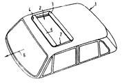
제1도는 슬라이딩 리드의 오프닝 전위에 의해 열린 루우프 오프닝과 작동상태에 위치한 바람편향플레이트를 구비하는 자동차 루우프의 사시도이다.1 is a perspective view of an automobile roof having a roof opening opened by the opening potential of the sliding lid and a wind deflection plate in an operating state.
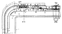
제2도는 슬라이딩 리드가 없이 도시된 자동차 루우프의 좌측 전면 코너의 부분 단면도이다.2 is a partial cross-sectional view of the left front corner of the automobile roof shown without a sliding lead.
제3도는 폐쇄상태로 도시된 슬라이딩 리드를 구비하는, 제2도에서의 선 III-III에 따른 단면도이다.3 is a cross-sectional view taken along line III-III in FIG. 2 with the sliding lid shown in the closed state.
제4도는 열려있는 슬라이딩 리드를 구비하는, 제3도에 해당하는 단면도이다.4 is a sectional view corresponding to FIG. 3 with an open sliding lid.
제5도는 닫힌 슬라이딩 리드를 구비하는, 제2도에서의 선 V-V의 단면도이다.5 is a cross-sectional view of the line V-V in FIG. 2 with a closed sliding lead.
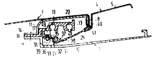
제6도는 제2도에서 선 VI-VI에 따른 부분절개 단면도이다.6 is a partial cross-sectional view taken along the line VI-VI in FIG.
* 도면의 주요부분에 대한 부호의 설명* Explanation of symbols for main parts of the drawings
1 : 자동차 루우프 2 : 루우프 오프닝1: car rooftop 2: rooftop opening
3 : 슬라이딩 리드 4 : 에어 가이드장치3: sliding lead 4: air guide device
5 : 바람 편향 플레이트 7 : 루우프 프레임5: wind deflection plate 7: roof frame
21,22 : 구동 케이블 26 : 결합웨브21,22: drive cable 26: coupling web
27 : 힌지 28 : 힌지축27: hinge 28: hinge axis
29 : 제어면 30 : 제어부재29: control surface 30: control member
31,33 : 힌지눈 41 : 고무버퍼31,33: hinge eye 41: rubber buffer
42 : 지지판 43 : 슬라이딩 슈우42: support plate 43: sliding shoe
45 : 진입장치 47 : 구동경사면45: entry device 47: driving slope
49 : 가이드홈49: guide groove
본 발명은 자동차 루우프용 에어 가이드 장치에 관한 것이다. 특히, 상기 에어 가이드 장치는 루우프 프레임에 의해 전면과 양측면을 에워싸는 루우프 오프닝을 포함하는 자동차 루우프용의 에어 가이드 장치에 관한 것인데, 상기 오프닝은 슬라이딩 리드에 의해 닫히게 되며, 루우프 프레임에 측방향으로 고정된 가이드 레일에 유도되고, 그 안에서 압축-보강 방식으로 이동 가능한 구동 케이블에 의해 구동된다. 상기 에어 가이드 장치는 스피링 응력에 의해 힌지축에 대해 루우프 오프닝의 전면 모서리를 따라서 회전 가능하고, 힌지축 방향으로 유도된 제어부재에 의한 슬라이딩 리드의 이동작용으로서 작동위치 및 정지위치로 조절가능한 바람 편향 플레이트를 포함한다. 제어부재는 슬라이딩 리드와 함께 이동하는 구동케이블에 의해 전위 될 수 있고 그와 관련된 제어면을 거쳐 바람 편향 플레이트를 조절할 수 있다.The present invention relates to an air guide device for a vehicle roof. In particular, the air guide device relates to an air guide device for a vehicle roof that includes a roof opening that encloses the front and both sides by a roof frame, the opening being closed by a sliding lead and fixed laterally to the roof frame. It is guided by a guide rail and driven by a drive cable movable therein in a compression-reinforced manner. The air guide device is rotatable along the front edge of the loop opening with respect to the hinge axis by the spring stress, and can be adjusted to the operating position and the stop position as a movement action of the sliding lid by the control member guided in the hinge axis direction. A deflection plate. The control member can be displaced by the drive cable moving with the sliding lead and can adjust the wind deflection plate via its associated control surface.
이러한 유형의 공지된 에어 가이드 장치(DE-PS 26 58 433)에 있어서, 제어부재는 플라스틱으로 되어있고, 케이블에 사출성형된다. 케이블과 제어부재는 두 부분으로 구성된 관으로 유도되는데, 그중 한 부분은 막혀있고, 나머지 부분에는 슬릿이 있다. 두 부분은 슬리이브에 의해 결합되어 있다. 상기 제어부재는 관의 슬릿 부분으로 유도된다. 상기 관은 서로 분리되어 간격져 배치된 힌지용 힌지핀으로서 제공되며, 슬릿 부분은 힌지들 사이에 위치한다. 제어부재는, 작동위치에 있을 때 진행방향과 평행하게 뒤쪽으로 돌출한 에어 가이드 장치에 일체로 형성되도록, 캠 경로와 공동작동하나, 캠 경로의 표면은 나선형으로 꼬여있고, 폐쇄방향으로 슬라이딩 리드의 전위가 일어나는 경우, 제어부재가 캠 경로에서 구동하고, 캠 경로의 꼬인 표면을 거쳐 에어 가이드 장치를 정지위치로 회전시켜서, 거기에 그대로 존재하도록 하는 방식으로, 제어부재와 공동 작동한다. 이 위치에서, 캠 경로는 하향돌출한다.In the known air guide device (DE-PS 26 58 433) of this type, the control member is made of plastic and is injection molded into the cable. The cable and the control member are guided by a two-piece tube, one of which is blocked and the other having a slit. The two parts are joined by a sleeve. The control member is guided to the slit portion of the tube. The tube is provided as a hinge pin for hinges spaced apart from each other, the slit portion being located between the hinges. The control member co-operates with the cam path so that it is integrally formed with the air guide device protruding rearward in parallel with the travel direction when in the operating position, but the surface of the cam path is spirally twisted, and the sliding lead When an electric potential occurs, the control member co-operates with the control member in such a manner that the control member drives in the cam path, rotates the air guide device to the stop position via the twisted surface of the cam path, and remains there. In this position, the cam path protrudes downward.
이러한 공지된 에어 가이드 장치의 단점은 양단부에서 힌지에 의해 제어부재의 이동이 제한된다는데 있는데, 그로인해 슬라이딩 리드의 가능한 오프닝 전위와 루우프 오프닝의 길이 또한 제한된다. 또한 에어 가이드 장치의 작동위치에서 뒤쪽으로 배향된 캠 경로중 일부는, 정지위치로 회전하는 동안, 지금까지는 보다 작은 전체 높이를 지니는 슬라이딩 루우프를 입수할 수 없었으므로 비교적 큰 회전공간을 필요로 한다. 또한 공지된 에어 가이드 장치는, 그의 리드가 리드의 전면 모서리 부근에 위치하는 축에 대해 회전하는 슬라이딩-리프팅 루우프에 사용하기에는 부적당한데, 그 이유는 공지된 구조물에서 슬라이딩 리드의 세로면에 고정되고 가이드관에 위치하는 케이블이 리드의 회전을 불가능하게 하기 때문이다. 또한, 에어 가이드 장치와 일체로 형성된, 나선형으로 꼬인 캠 경로 표면의 제작은 상당한 제작비용을 발생시킨다.A disadvantage of this known air guide device is that the movement of the control member is limited by the hinges at both ends, thereby limiting the possible opening potential of the sliding lid and the length of the loop opening. In addition, some of the cam paths oriented rearward from the operating position of the air guide device require a relatively large rotational space while rotating sliding to the stop position has not been available so far with a smaller overall height. Also known air guide devices are inadequate for use in sliding-lifting loops in which their leads rotate about an axis located near the front edge of the lid, because in the known structure they are fixed to the longitudinal surface of the sliding lid and guide This is because the cable located in the tube makes the lead impossible to rotate. In addition, the fabrication of the spirally twisted cam path surface integrally formed with the air guide device incurs significant fabrication costs.
케이블 가이드 관의 제작 및 설치는 많은 비용을 발생시키지 않으며, 2개의 상이한 관부분은 슬라이브에 의해 결합되고, 결합요소에 의해 고정된 루우프 프레임에 대해 몇배로 안정하게 고정되는 반면, 리드의 측면에 고정된 케이블의 진입은 리드 가이드와 나란하게 이루어진다. 제어부재와 캠 경로 사이의 지렛대비가 불리하기 때문에, 에어 가이드 장치를 회전시키기 위해 상당한 힘이 가해져야 하고 이것은 닫힌 리드위치로의 리드 전위의 마지막 단계에서 구동을 어렵게 한다.The fabrication and installation of the cable guide tube does not incur a lot of costs, and the two different tube parts are joined by the slave and fixed several times stably with respect to the loop frame fixed by the coupling element, while on the side of the lead Entry of the fixed cable takes place side by side with the lead guide. Since the lever contrast between the control member and the cam path is disadvantageous, considerable force must be applied to rotate the air guide device, which makes it difficult to drive in the last stage of lead dislocation to the closed lead position.
본 발명의 목적은 슬라이딩 루우프 및 낮은 높이의 슬라딩-리프팅 루우프에 모드 적절하며, 설비가 복잡하지 않은 간단한 유형의 부품들로 구성되고, 리드의 슬라이딩 구동이 어렵지 않게 이루어질 수 있는 에어 가이드 장치를 제공하는데 있다.It is an object of the present invention to provide an air guide device which is mode-suitable for sliding loops and low-height sliding-lifting loops, which consists of simple types of components that are not complicated in installation and which makes sliding driving of the leads not difficult. It is.
본 발명에 따르면, 루우프 프레임에 의해 전면과 양 측면이 에워싸인 루우프 오프닝을 포함하는, 자동차 루우프용 에어 가이드 장치가 제공되는데, 상기 오프닝은 루우프 프레임에 축방향으로 고정된 가이드 레일에 유도되고 그 안에서 압축보강방식으로 이동가능한 구동 케이블에 의해 구동되는 슬라이딩 리드에 의해 닫힐 수 있게 되어 있으며, 상기 에어 가이드 장치는 스프링 응력에 의해 힌지축에 대해 루우프 오프닝의 전면 모서리를 따라서 회전가능하고 힌지 축 방향으로 유도된 제어부재에 의한 슬라이딩 리드의 이동작용으로써, 작동위치 및 정지위치로 조절가능한 바람 편향플레이트를 포함하는데, 여기에서 제어부재는 슬라이딩 리드와 함께 이동하는 구동케이블에 의해 전위될 수 있고 그와 관련하는 제어면을 거쳐 바람 편향 플레이트를 조절하며, 상기 제어면은 실제로 평면으로 되어 있고 힌지 축과 바람 편향 플레이트사이에 위치하고 앞쪽에 고정된 자동차루우프 바로 아래에 가로놓여 있는 결합웨브의 상측면에 구비되며, 상기 제어부재는 슬라이딩 리드에 대해 구동 케이블중 하나에 고정되고, 바람 편향 플레이트를 회전시키기 위해, 제어면에서 구동하여 바람 편향 플레이트의 정지 상태에서 제어면위에 정지한다.According to the present invention there is provided an air guide device for a vehicle roof, comprising a roof opening surrounded by a roof frame, the front and both sides of which are guided to and guided axially fixed to the roof frame. It can be closed by a sliding lead driven by a drive cable which is movable in compression reinforcement, the air guide device being rotatable along the front edge of the loop opening with respect to the hinge axis by a spring stress and leading in the hinge axis direction. By means of the movement of the sliding lid by the controlled control member, it comprises a wind deflection plate, which is adjustable in the operating position and in the stop position, wherein the control member can be displaced by and associated with the drive cable moving with the sliding lead. The wind deflection plate The control surface is provided on the upper side of the coupling web which is actually planar and intersects directly below the vehicle loop fixed in front and located between the hinge axis and the wind deflection plate, wherein the control member is provided with respect to the sliding lid. It is fixed to one of the drive cables and is driven on the control surface to stop on the control surface in the stationary state of the wind deflection plate in order to rotate the wind deflection plate.
실제로 평면인 제어면은 단지 적은 제작비용만을 필요로 하고 힌지축 아래에 회전공간을 필요로 하지 않으므로, 에어 가이드 장치는 슬라이딩 루우프 또는 슬라이딩-리프팅 루우프 구조물의 총 높이에 어떤 나쁜 영향도 미치지 않게 된다. 상기 제어부재는 힌지축으로부터 상당한 거리를 두고 제어면에 작용할 수 있으므로, 바람 편향 플레이트를 정지위치로 회전시키기 위해 상당한 힘의 행사를 필요로 하지 않게 된다.Since the control plane, which is actually planar, requires only a small manufacturing cost and no rotational space below the hinge axis, the air guide device does not have any adverse effect on the total height of the sliding loop or the sliding-lifting loop structure. The control member can act on the control surface at a considerable distance from the hinge axis, thereby eliminating the need for significant force to rotate the wind deflection plate to a stationary position.
구동 케이블에 제어부재를 고정시키는 것은 별개로 하고, 에어가이드 장치에 대해 다른 부품은 필요하지 않는데, 왜냐하면 제어면이 바람 편향플레이트를 힌지축에 결합시키는 결합웨브상에 직접 제공되기 때문이다. 본 발명의 에어 가이드 장치는 구동 케이블이 앞쪽에 고정된 자동차 루우프 아래에 유도되도록 구비된, 모든 슬라이딩 루우프와 슬라이딩-리프팅 루우프 구조물에서 간단한 방식으로 사용될 수 있다.Securing the control member to the drive cable is separate and no other components are required for the airguide device because the control surface is provided directly on the coupling web that couples the wind deflection plate to the hinge axis. The air guide device of the present invention can be used in a simple manner in all sliding loops and sliding-lifting loop structures, provided that the drive cables are guided underneath the vehicle roof fixed in front.
결합웨브는 바람 편향 플레이트와 일체로 금속판으로 형성될 수 있고 힌지 눈을 형성하기 위해 전방 단부에서 말리게 된다. 이러한 것은 결함웨브, 바람 편향 플레이트 및 힌지 눈이 동일한 금속판 물질로서 일체로 형성되어 있기 때문에 부품수를 감소시키게 된다.The coupling web may be formed of a metal plate integrally with the wind deflection plate and dried at the front end to form a hinged eye. This reduces the number of parts because the defect web, wind deflection plate and hinge eyes are integrally formed from the same metal sheet material.
에어 가이드 장치를 그 작동위치에서 루우프 오프닝의 전면 모서리에 적용시키는 것은, 루우프 오프닝의 전면모서리를 구성하는 수직 루우프 플랜지에 인접하여 있고 거기에 평행하게 배향된, 전방 크랭크부와 함께 바람 편향 플레이트를 형성함으로써 이루어지므로, 바람 편향 플레이트는 자동차 루우프의 외부면 높이에서 그의 상측 모서리가 놓이게 되고, 결합웨브가 루우프 모서리 플랜지 아래에 부착된다.Applying the air guide device to the front edge of the loop opening in its operating position forms a wind deflection plate with the front crank portion adjacent to and oriented parallel to the vertical loop flange forming the front edge of the loop opening. By doing so, the wind deflection plate is placed at its upper edge at the height of the outer surface of the vehicle roof, and the coupling web is attached under the roof edge flange.
바람 편향 플레이트의 작동위치는 고무버퍼 또는 그와 유사한 매개체를 통해, 루우프 플랜지의 하부 모서리에 대해 결합웨브를 부착시키므로써 한정될 수 있다. 따라서, 바람 편향 플레이트의 작동위치로서 회전이동은 간단한 방식으로 덜거덕거릴 염려없이 한정될 수 있다.The operating position of the wind deflection plate can be defined by attaching the coupling web to the lower edge of the loop flange via a rubber buffer or similar medium. Thus, the rotational movement as the operating position of the wind deflection plate can be defined without fear of rattling in a simple manner.
제어부재, 그의 슬라이딩 가이드 및 구동 케이블에 대한 그의 결합부의 선호된 구조물은, 제어부재가 루우프 프레임의 전방 부분으로 유도된 지지판을 포함하도록 되어 있는데, 상기 지지판은 슬라이딩 슈우로서 루우프 오프닝을 향하고 있는 그외 모서리에서 구성되며, 그의 하측면에 의해 제어면과 결합되고 그의 상측면에 의해 루우프 프레임의 전방부로 이동가능하게 유도된다. 구동 케이블에 견고하게 부착되어 있는 진입장치는 지지판에 고정된다. 제어부재에 대한 슬라이딩 가이드는 루우프 프레임의 가이드 홈에서 이동가능하게 유도되는, 가이드 슈우로서 루우프 오프닝으로부터 떨어져서 배향된 지지판의 모서리를 형성하므로써 개선될 수 있다.The preferred structure of the control member, its sliding guide and its coupling to the drive cable is such that the control member comprises a support plate which is guided to the front part of the roof frame, the support plate being the other edge facing the roof opening as a sliding shoe. Is coupled to the control surface by its lower side and is movably guided to the front of the loop frame by its upper side. The entry device, which is firmly attached to the drive cable, is fixed to the support plate. The sliding guide for the control member can be improved by forming an edge of the support plate oriented away from the roof opening as a guide shoe, which is guided movably in the guide groove of the loop frame.
바람 편향 플레이트에 대해 연속적인 회전이동을 위해, 슬라이딩 슈우의 하측면이 슬라이딩 슈우에 위치한 구동경사면에 인접하도록 하는 것이 선호되는데, 상기 경사면은 바람 편향 플레이트의 회전 이동을 제어한다.For continuous rotational movement with respect to the wind deflection plate, it is preferred that the lower side of the sliding shoe is adjacent to the drive inclined surface located on the sliding shoe, the inclined surface controlling the rotational movement of the wind deflection plate.
유리하게도, 에어 가이드 장치는 그 이동-제어요소에 관해서 종축의 한쪽 측면에 배열되므로, 자동차의 종방향 중앙축이 양측면 각각에, 제어면을 보유하는 결합웨브와 그와 공동작용하는 제어부재가 힌지와 함께 구비된다.Advantageously, the air guide device is arranged on one side of the longitudinal axis with respect to its movement-control element, so that the longitudinal center axis of the vehicle is hinged on each of the two sides, the coupling web holding the control surface and the control material co-operating therewith. It is provided with.
본 발명은 첨부된 도면을 참조로하여 보다 상세히 기술될 것이다. 제1도에서 도시된 바와 같이, 루우프 오프닝(2)은 고정된 자동차 루우프(1)의 전방부에 존재하며, 상기 오프닝에는 열린상태로 도시된 슬라이딩-리프팅 루우프의 슬라이딩 리드(3)가 결합되어 있다. 루우프 오프닝(2)의 전방 모서리에는 에어 가이드 장치(4)가 있으며, 바람 편향 플레이트(5)가 루우프 오프닝(2)의 폭에 걸쳐 연장되어 있고, 슬라이딩 리드(3)가 열리게 되는 경우, 고정된 자동차 루우프(1) 상부로 그의 후방 모서리에 의해 상승된다. 바람 편향 플레이트(5)의 작동위치는 제1도에 도시되어 있다. 진행방향을 표시하는 화살표 "6"은 자동차의 이동방향을 표시하는데, 위치명 "전·후방 및 좌·우측"을 설명한다. 제1도에서, 루우프 프레임(7)이 또한 도시되어 있는데, 상기 루우프 프레임은 전면과 양측면에서 루우프 오프닝(2)을 에워싸고 있으며, 이후에 다른 도면을 참조로하여 보다 상세히 기술될 것이다.The invention will be described in more detail with reference to the accompanying drawings. As shown in FIG. 1, the
제2도에서는 슬라이딩-리프팅 루우프 구조물에서 단지 에어 가이드 장치(4)와 다른 구성요소들의 좌측 절반이 도시되어 있다. 에어 가이드 장치의 우측 절반은, 대칭축을 형성하고 선 V-V와 일치하는 자동차의 종방향 중앙축에 대해 거울상이다. 이러한 대칭으로 인해, 단지 장치의 좌측 절반만이 이후에 기술될 것이다. 루우프 오프닝의 모서리는, 그의 하측 모서리에서 180°위로 휘어져 있는 수직 루우프 모서리 플랜지에 의해 전면, 양측면 및 후면에 형성되어 있다(도시되지 않음).In FIG. 2 only the left half of the
슬라이딩 리드(3)는 그의 하부면에 리드 보강체(9)를 구비하는데, 상기 리드 보강체는 슬라이딩 리드(3)의 외측 림에서 하향하여 크랭크 모양으로 구부려져 있다. 슬라이딩 리드(3)와 리드 둘레에 걸쳐 있는 리드 보강체(9)의 인접한 하향 플랜지에는, 슬라이딩 리드가 닫혀있을 때, 제3도와 제5도에서 도시된 바와 같이, 루우프 모서리 플랜지(8)에 대해 그 주위를 밀봉 가능하게 아래로부터 끼워져 있다.The sliding
루우프 오프닝(2)을 에워싸고 아래로부터 상기 오프닝을 보강하는 루우프 프레임(7)은, 상측 고정 프레임(11), 전면과 양측면이 일체로 되어있는 물 채널(12) 및 전면과 양측면에 일정한 윤곽을 보유하는 가이드 프레임(13)의 3부분으로 구성되는데, 상기 가이드 프레임은 그의 측면부에서, 슬라이딩 요소(도시되지 않음)로서 가이드 레일을 형성하고, 상기 가이드 레일에 의해 슬라이딩 리드(3)가 이동 가동하게 유도된다. 외측 모서리에서는, 고정 프레임(11), 물 채널(12) 및 가이드 프레임(13)이 각각 고정 플랜지(14)(15)(16)를 구비한다. 고정 플랜지(14)(15) 및 (16)은 서로 평행하게 배치되고 "17"에서 함께 나사로 죄어져 있다. 자동차 루우프(1)에 고정된 고정 프레임은 내측에 수직으로 하향 배향된 플랜지(18)를 구비하는데, 그 상기 플랜지 둘레는 루우프 모서리 플랜지(8)가 감싸고 있다. 단일-편인 가이드 프레임(13)은 모든 그의 프레임부분 즉, 전면과 측면들과 함께, 고정된 자동차 루우프(1) 아래에서 루우프 모서리 플랜지(8)와 간격을 두고서 위치한다. 또한, 일체로 형성된 물 채널(12)은 가이드 프레임(13) 및 슬라이딩 리드(3)와 루우프 모서리 플랜지(8) 사이에 위치하는 모서리 갭을 포함하는 슬라이딩 리드(3)의 외측 모서리 아래에서 전면과 측면들에 결합된다.The
가이드 프레임(13)은 2개의 상호 인접한 하향 오픈 케이블 가이드 덕트(19)(20)를 포함하는데, 상기 덕트에는 유연성 구동 케이블(21)(22)이 각각 종방향으로 미끄러지듯이 압축보강방식으로 유도된다. 제5도에서 도시된 바와 같이, 가이드 프레임(13)에 고정된 구동장치(24)의 구동 피니언(23)이 회전하므로써, 그의 케이블 가이드 덕트에서 반대방향으로 배치되어 있는 구동 케이블(21)(22)과 강제 이송되어 결합된다. 이러한 구동 시스템은 수동식 크랭크(25)에 의해서, 또는 전기 모터에 의해서 제5도에서 도시된 바와 같이 구동된다. 제2,3 및 6도에서의 구동 케이블(22)은 간결하게 위해 제4도에서 나타나지 않은 것으로 보여진다.The
에어 가이드 장치(4)의 바람 편향 플레이트(5)는 루우프 오프닝의 전방 모서리를 따라서 연장되어 있는 결합웨브(26)를 거쳐서, 힌지(27)에 부착되어 있는데, 상기 힌지는 루우프 오프닝의 전면 모서리에 편행하게 연장된 힌지 축(28)(제2도)을 한정하며, 상기축에 대해 바람 편향 플레이트(5)가 회전될 수 있다. 결합웨브(26)의 상측면은 구동 케이블(22)에 대해 기술된 방식으로 고정된 제어부재(30)와 함께 공동작동하는, 평면인 제어면(29)을 형성한다.The
이러한 실시유형에서, 결합웨브(26)은 바람 편향 플레이트(5)와 일체로 금속판으로 형성되어 있고 힌지눈(31)을 형성하기 위해 그의 전면모서리에서 말려있다. 힌지핀(32)이 힌지눈(31)을 통과하여, 힌지눈(31)의 양측면에서 거리를 두고서 나사(34)에 의해 가이드 프레임(13)의 수평 플랜지(35)에 고정된, 힌지(27)의 힌지 구성요소(36)의 힌지눈(33)을 통과하게 된다. 힌지눈(31)과 (33) 사이의 공간에서, 힌지핀(32)이 꿰어진, 레그 스프링(37)의 스프링 회전이 일어나는데, 상기 스프링은 결합웨브(26)에 대한 하나의 레그(38)와 고정된 힌지구성요소(36)에 대한 다른 하나의 레그(39)를 아래로부터 지지한다.In this embodiment, the
레그 스프링(37)은 결합웨브(26)에 엇갈려 있고, 따라서 바람 편향 플레이트(5)는 반시계 방향으로 회전하게 되므로, 제어면(29)이 제어부재(30)에 의해 이완될 경우, 결합웨브(26)와 바람 편향 플레이트(5)는 제3도에서 도시된 정지위치에서 제4도에서 도시된 작동위치로 회전된다. 결합웨브(26)는 전면 고정 자동차 루우프(1) 아래에 연장되므로, 가이드 프레임(13)상에 종방향으로 미끄러지듯이 유도된 제어부재(30) 아래에 위치하게 된다.The
제3도와 제4도에서 도시된 바와 같이, 바람 편향 플레이트(5)는, 작동위치(제4도)에서 전면 루우프 모서리 플랜지(8)에 인접하여 평행하게 배열된 전방 크랭크부(40)를 구비한다. 크랭크부(40)의 높이는 크랭크부(40)가 자동차 루우프(1)의 외측면의 높이에서 상단에 놓이게 배열되므로, 바람 편향 플레이트(5)의 외측면은 단계적으로 전이하는 자동차 루우프(1)의 외측면에 인접하게 된다. 루우프 모서리 플랜지(8) 아래에는, 크랭크부(40)가 결합웨브(26)와 일체로 단단하게 결합되어 있다.As shown in FIG. 3 and FIG. 4, the
바람 편향 플레이트(5)의 작동위치는 고무버퍼(41) 매개체 또는 그와 유사한 것을 통해, 제4도에서 도시된 바와 같이 루우프 모서리 플랜지(8)의 하측 모서리에 대해 결합웨브(26)를 접속시키므로써 정의된다. 고무버퍼(41)는 결합웨브(26)의 공동에 뭇상단을 가압하여 고정된다.The operating position of the
제어부재(30)는, 본 발명의 실시유형에서 가이드 프레임(13)상의 루우프 프레임(7)의 전면부에 유도된, 지지판(42)을 포함하는데, 상기 지지판은 슬라이딩 슈우(43)로서 루우프 오프닝(2)을 향해 면해 있는 그의 모서리에서 형성된다. 이를 위해, 지지판(42)의 하향 배향 플랜지에는 그 둘레에 사출 성형된 적절한 플라스틱을 보유한다. 제2도와 3도에서 도시된 정지위치에서, 루우프 오프닝(2)은 슬라이딩 리드(3)에 의해 닫혀 있으며, 슬라이딩 슈우(43)는 제어면(29)을 지지하는 반면, 이와 동시에 고무버퍼(41)는 물 채널(12)의 내측면을 지지하여 바람 편향 플레이트(5)가 슬라이딩 리드(3) 아래의 정지위치에 덜거덕거림이 없이 존재하게 된다. 슬라이딩 슈우(43)는, 그의 상측면(44)에 의해 루우프 프레임(7)의 전면부에 대해, 본 발명의 실시유형에서는 가이드 프레임(13)의 하측면에 대해 미끄러지듯이 유도된다. 지지판(42)에는, 진입장치(45)가 고정되어 있는데, 상기 진입 장치는 구동 케이블(22) 주위를 감싸고 있는 금속판 스트립으로 형성되어, 그 결과 제어부재(30)는 구동 케이블(22)에 고정되어 상기 슬라이딩 케이블의 슬라이딩 이동에 참여한다.The
루우프 오프닝을 떨어져서 향하고 있는 지지판(42)의 모서리를 가이드 프레임(13)의 본 발명의 실시유형에서, 루우프 프레임(7)의 가이드 홈(49)(제4도)에 미끄러지듯이 유도되는, 가이드 슈우드(46)로서 구성된다.In the embodiment of the present invention of the
제어면(29)과 관련 된, 슬라이딩 슈우(43)의 하측면은 제6도에서 도시된 구동 경사면(47)에 의해 인접하게 된다. 구동경사면(47)은, 결합웨브(26)의 좌측 모서리(48) 위에서 구동하므로써(제2도), 바람 편향 플레이트(5)가 작동위치에서 레그 스프링(37)의 힘에 대항하여 정지 위치로 회전하도록 한다. 구동경사면(47)은 모서리(48)와 공동작동하여, 바람 편향 플레이트(5)의 회전이동을 제어한다.The lower side of the sliding
슬라이딩-리프팅 루우프의 작동요소와 제2도에서 도시된 에어 가이드 장치의 배치에 있어서, 슬라이딩 리드(3)는 닫힌 상태로 배치되고 에어 가이드 장치(4)는 정지위치로 배치된다. 만일 슬라이딩 리드(3)가 이 상태에서 열리게 된다면, 구동장치(24)는, 구동케이블(22)이 왼쪽을 향해 전위되는 방식으로 작동된다. 슬라이딩 루우프와 슬라이딩-리프팅 루우프에서 언제나 있는 일로서, 슬라이딩 리드(3)의 후방 모서리는, 리드가 고정된 자동차 루우프(1) 아래로 전위될 수 있도록 하기 위해, 초기에 낮추어진다. 제어부재(30)는 제어면(29)상에서 좌측을 향해 이동하는데, 그 결과가 초기에 에어 가이드 장치(4)는 정지 위치에 존재하게 된다.In the arrangement of the operating element of the sliding-lifting loop and the air guide device shown in FIG. 2, the sliding
표시된 방향으로 구동 케이블(22)의 전위가 계속되므로써, 제어부재(30)는, 슬라이딩 리드(3)가 반쯤 열린상태에 도달할 때까지 제어면(29)에 머무르게 되는데, 상기 상태에서, 바람 편향 플레이트(5)는 슬라이딩 리드(3)의 전면 모서리를 치지 않고서 그의 작동위치를 향해 상측으로 회전할 수 있다. 바람 편향 플레이트(5)의 외측 회전은 갑자기 일어나지는 않지만 경사면(47)을 따라서 결합웨브(26)의 모서리(48)의 느린 슬라이딩의 결과, 슬라이딩 속도는 구동 경사면(47)의 경사각과 구동 케이블(22)의 전위 속도에 의존하게 된다. 제어면(29)이 제어부재(30)에 의해 완전히 이완된 후, 제어부재(30)는 리드 오프닝 전위중에 가이드 프레임(13)의 코오너 벤드를 지나 가이드 프레임의 측부를 통과하고 최종적으로 리드의 전위 기능을 하는, 그의 한정위치에 도달하게 된다. 제어부재(30)는 자유롭게 이동할 수 있고 루우프 구조물의 다른 구성요소와도 충돌하지 않는다.As the potential of the
역으로, 열린 슬라이딩 리드(3)가 닫힌 상태로 이동되는 경우, 구동케이블(22)은 우측을 향한 이동 방향으로 구동되는데, 그 결과 제어부재(30)는 가이드 프레임(13)의 둥근 코오너를 통과한 후, 결합 웨브(26)의 모서리(48)에 접근하게 되고 최종적으로 상기 모서리상의 구동 경사면(47)과 일치하게 된다. 구동 이동이 계속되므로써, 바람 편향 플레이트(5)는, 제어부재(30)가 제어면(29)상의 하측면에 도달할 때까지 느린속도로 하향 이동하여 레그 스피링(37)의 힘에 대항하여 힌지축(28)에 대해 회전하여, 에어 가이드 장치(4)가 정지위치로 도달하게 한다.Conversely, when the open sliding
슬라이딩 리드의 폐쇄전위의 최종단계에서 있어서, 슬라이딩 리드의 후방 모서리가 그의 닫힌 상태로 올라올때까지, 제어부재(30)는 제어면(29)에 그대로 머무르고 최종적으로는 제2도에서 도시된 초기 위치에 도달하게 된다.In the final stage of the closing potential of the sliding lid, the
슬라이딩-리프팅 루우프를 보유하는 루우프 구조물에서, 구동 케이블(22)은, 후방 환기 갭을 형성하도록 자동차 루우프(1) 상부의 슬라이딩 리드(3)의 후방 모서리에 의해 상기 리드(3)를 위로 올리기 위해, 우측을 향해 구동된다. 여기에서, 제어부재(30)는 제어면(29)상에서 우측으로 이동하지만, 슬라이딩 리드의 최대 회전상태에 도달하기 전에 상기 제어면(29)을 떠나지 않는다. 따라서, 에어 가이드 장치(4)는 슬라이딩 리드(3)의 내외측 회전이동시 정치상태로 존재하게 된다.In a loop structure having a sliding-lifting loop, the
결합웨브(26)와 이에 다른 제어면(29)의 길이는 루우프 구조물의 형태에 의존할 것이다. 슬라이딩 루우프에 있어서, 결합웨브(26)는 제2도에서의 위치에서 제어부재(30)의 우측으로 즉각적으로 이동할 수 있다. 대조적으로 슬라이딩-리프팅 루우프에서, 결합웨브(26)은 제2도에서 도시된 바와 같이, 구동장치(24)를 향해 계속 이동한다.The length of the
Claims (8)
Applications Claiming Priority (2)
| Application Number | Priority Date | Filing Date | Title |
|---|---|---|---|
| DE3908750A DE3908750C1 (en) | 1989-03-17 | 1989-03-17 | |
| DEP3908750.6 | 1989-03-17 |
Publications (2)
| Publication Number | Publication Date |
|---|---|
| KR900014170A KR900014170A (en) | 1990-10-23 |
| KR950012260B1 true KR950012260B1 (en) | 1995-10-16 |
Family
ID=6376554
Family Applications (1)
| Application Number | Title | Priority Date | Filing Date |
|---|---|---|---|
| KR1019900003589A KR950012260B1 (en) | 1989-03-17 | 1990-03-17 | Air guide device for automobile roof |
Country Status (13)
| Country | Link |
|---|---|
| US (1) | US4971387A (en) |
| JP (1) | JPH0755622B2 (en) |
| KR (1) | KR950012260B1 (en) |
| BR (1) | BR9001269A (en) |
| CA (1) | CA2011523C (en) |
| DE (1) | DE3908750C1 (en) |
| ES (1) | ES2020639A6 (en) |
| FR (1) | FR2644409B1 (en) |
| GB (1) | GB2232645B (en) |
| IT (1) | IT1240929B (en) |
| MX (1) | MX174387B (en) |
| NL (1) | NL193449C (en) |
| SE (1) | SE469272B (en) |
Families Citing this family (13)
| Publication number | Priority date | Publication date | Assignee | Title |
|---|---|---|---|---|
| GB9218824D0 (en) * | 1992-09-02 | 1992-10-21 | Jaguar Cars | Wind defelctor for vehicle sunroof |
| DE19714492B4 (en) * | 1997-04-08 | 2008-11-20 | Bayerische Motoren Werke Aktiengesellschaft | Actuating device for a wind deflector on a vehicle sunroof |
| DE19820573C2 (en) * | 1998-05-08 | 2002-03-07 | Webasto Karosseriesysteme | Vehicle roof with sliding cover and wind deflector |
| DE19911551B4 (en) * | 1999-03-16 | 2009-06-10 | Webasto Ag | Wind deflector for a vehicle roof |
| US6199944B1 (en) | 1999-06-04 | 2001-03-13 | Asc Incorporated | Spoiler sunroof |
| US6299245B1 (en) | 1999-11-15 | 2001-10-09 | Honda Giken Kogyo Kabushiki Kaisha | Wind deflector and sunshade stopping system, and method of using same |
| US6273501B1 (en) * | 2000-02-15 | 2001-08-14 | Meritor Light Vehicle Systems, Inc. | Simplified wind deflector for vehicle roof closure |
| US6666503B1 (en) | 2002-09-27 | 2003-12-23 | Honda Giken Kogyo Kabashiki Kaishu | Pop-up vehicle wind deflector |
| US6705673B1 (en) | 2002-09-27 | 2004-03-16 | Honda Giken Kogyo Kabushiki Kaisha | Latched wind deflector system |
| EP2103468A1 (en) * | 2008-03-18 | 2009-09-23 | ArvinMeritor GmbH | Vehicle roof that can open |
| DE102015120408B3 (en) * | 2015-11-25 | 2017-03-09 | Webasto SE | Cover of a vehicle roof with insert in a plastic mold section |
| CN107953760B (en) * | 2017-11-23 | 2019-07-05 | 杭州科技职业技术学院 | Automobile skylight device |
| EP3795397B1 (en) | 2019-09-17 | 2023-11-01 | Inalfa Roof Systems Group B.V. | Wind deflector assembly |
Family Cites Families (7)
| Publication number | Priority date | Publication date | Assignee | Title |
|---|---|---|---|---|
| FR2261893B1 (en) * | 1974-02-26 | 1976-06-25 | Peugeot & Renault | |
| DE2658433C3 (en) * | 1976-12-23 | 1981-01-08 | Dr.Ing.H.C. F. Porsche Ag, 7000 Stuttgart | Air guiding device for a sunroof of a motor vehicle |
| DE3137191A1 (en) * | 1981-09-18 | 1983-03-31 | Rockwell Golde Gmbh, 6000 Frankfurt | WIND RESISTANT DEVICE ON A MOTOR VEHICLE ROOF |
| DE3401550A1 (en) * | 1984-01-18 | 1985-07-18 | Webasto-Werk W. Baier GmbH & Co, 8035 Gauting | WIND DEFLECTORS FOR VEHICLES |
| DE3446916A1 (en) * | 1984-12-21 | 1986-07-03 | Webasto-Werk W. Baier GmbH & Co, 8035 Gauting | VEHICLE ROOF |
| IT8553228V0 (en) * | 1985-04-15 | 1985-04-15 | Gilardini Spa | SUNROOF FOR VEHICLES |
| DE3515066A1 (en) * | 1985-04-26 | 1986-10-30 | Webasto Werk Baier Kg W | SLIDING ROOF FOR VEHICLES |
-
1989
- 1989-03-17 DE DE3908750A patent/DE3908750C1/de not_active Expired - Fee Related
-
1990
- 1990-02-26 ES ES9000556A patent/ES2020639A6/en not_active Expired - Lifetime
- 1990-02-28 CA CA002011523A patent/CA2011523C/en not_active Expired - Fee Related
- 1990-03-05 US US07/489,116 patent/US4971387A/en not_active Expired - Fee Related
- 1990-03-13 NL NL9000573A patent/NL193449C/en not_active IP Right Cessation
- 1990-03-14 GB GB9005768A patent/GB2232645B/en not_active Expired - Fee Related
- 1990-03-15 IT IT4811A patent/IT1240929B/en active IP Right Grant
- 1990-03-15 FR FR909003350A patent/FR2644409B1/en not_active Expired - Lifetime
- 1990-03-16 MX MX019924A patent/MX174387B/en unknown
- 1990-03-16 SE SE9000935A patent/SE469272B/en not_active IP Right Cessation
- 1990-03-16 JP JP2066772A patent/JPH0755622B2/en not_active Expired - Lifetime
- 1990-03-17 KR KR1019900003589A patent/KR950012260B1/en not_active IP Right Cessation
- 1990-03-19 BR BR909001269A patent/BR9001269A/en not_active IP Right Cessation
Also Published As
| Publication number | Publication date |
|---|---|
| DE3908750C1 (en) | 1990-06-07 |
| MX174387B (en) | 1994-05-12 |
| NL193449C (en) | 1999-11-02 |
| CA2011523C (en) | 1994-05-10 |
| FR2644409A1 (en) | 1990-09-21 |
| ES2020639A6 (en) | 1991-08-16 |
| CA2011523A1 (en) | 1990-09-17 |
| GB2232645A (en) | 1990-12-19 |
| FR2644409B1 (en) | 1991-11-22 |
| SE469272B (en) | 1993-06-14 |
| NL9000573A (en) | 1990-10-16 |
| KR900014170A (en) | 1990-10-23 |
| NL193449B (en) | 1999-07-01 |
| US4971387A (en) | 1990-11-20 |
| GB2232645B (en) | 1992-11-11 |
| IT1240929B (en) | 1993-12-27 |
| SE9000935D0 (en) | 1990-03-16 |
| JPH0755622B2 (en) | 1995-06-14 |
| IT9004811A0 (en) | 1990-03-15 |
| SE9000935L (en) | 1990-09-18 |
| GB9005768D0 (en) | 1990-05-09 |
| IT9004811A1 (en) | 1991-09-15 |
| JPH02283528A (en) | 1990-11-21 |
| BR9001269A (en) | 1991-03-26 |
Similar Documents
| Publication | Publication Date | Title |
|---|---|---|
| KR950012260B1 (en) | Air guide device for automobile roof | |
| US6457769B2 (en) | Motor vehicle sunroof | |
| CN106114151B (en) | Shading device for a window pane of a motor vehicle | |
| KR101209499B1 (en) | Unit support for a motor vehicle door | |
| US4685724A (en) | Sliding roof for vehicles | |
| US4179156A (en) | Vehicle sun roof cover | |
| US20090091160A1 (en) | Open roof construction | |
| JPH0515571B2 (en) | ||
| EP0187398A1 (en) | Sliding roof for a vehicle | |
| US5910077A (en) | Door actuated extendable strap handle | |
| JPH0137289Y2 (en) | ||
| JPS6285716A (en) | Slide roof for automobile | |
| CA1057337A (en) | Sliding roof for automobiles | |
| US6560930B2 (en) | Guide device for a window having a guide rail mounted to pivot substantially parallel to a plane of the window | |
| US6866336B2 (en) | Wind deflector arrangement for a motor vehicle roof | |
| JP3840350B2 (en) | Shielding device for vehicle opening | |
| US4342482A (en) | Sliding sunroof with ventilator | |
| JP4101360B2 (en) | Open roof structure for vehicles | |
| US4895410A (en) | Sliding and lifting roofs | |
| US4452013A (en) | Opening and closing mechanism for a vehicle sunroof | |
| CA2087113C (en) | Blocking device for sliding-lifting roofs for automobiles | |
| US5081792A (en) | Window regulator with orthogonal pushout for flush window | |
| JP3667799B2 (en) | Roof panel assembly | |
| US5306070A (en) | Sliding-lifting roof for automobiles | |
| CN112297796A (en) | Method of operating a closure for an open roof construction and open roof construction |
Legal Events
| Date | Code | Title | Description |
|---|---|---|---|
| A201 | Request for examination | ||
| E902 | Notification of reason for refusal | ||
| G160 | Decision to publish patent application | ||
| E701 | Decision to grant or registration of patent right | ||
| GRNT | Written decision to grant | ||
| FPAY | Annual fee payment |
Payment date: 20001014 Year of fee payment: 6 |
|
| LAPS | Lapse due to unpaid annual fee |