KR950009713B1 - Metal support for a catalyst and method for its production - Google Patents
Metal support for a catalyst and method for its production Download PDFInfo
- Publication number
- KR950009713B1 KR950009713B1 KR1019870013092A KR870013092A KR950009713B1 KR 950009713 B1 KR950009713 B1 KR 950009713B1 KR 1019870013092 A KR1019870013092 A KR 1019870013092A KR 870013092 A KR870013092 A KR 870013092A KR 950009713 B1 KR950009713 B1 KR 950009713B1
- Authority
- KR
- South Korea
- Prior art keywords
- catalytic converter
- corrugated
- plate
- converter support
- innermost layer
- Prior art date
Links
- 239000002184 metal Substances 0.000 title claims description 22
- 238000000034 method Methods 0.000 title claims description 8
- 238000004519 manufacturing process Methods 0.000 title description 13
- 239000003054 catalyst Substances 0.000 title 1
- 230000003197 catalytic effect Effects 0.000 claims description 35
- 239000000463 material Substances 0.000 claims description 14
- 238000004804 winding Methods 0.000 claims description 7
- 238000005304 joining Methods 0.000 claims description 6
- 238000003466 welding Methods 0.000 claims description 4
- 239000010410 layer Substances 0.000 description 28
- 239000007789 gas Substances 0.000 description 4
- 238000005219 brazing Methods 0.000 description 2
- 238000004026 adhesive bonding Methods 0.000 description 1
- 238000006243 chemical reaction Methods 0.000 description 1
- 239000011248 coating agent Substances 0.000 description 1
- 238000000576 coating method Methods 0.000 description 1
- 238000012986 modification Methods 0.000 description 1
- 230000004048 modification Effects 0.000 description 1
- 239000002356 single layer Substances 0.000 description 1
- 239000000758 substrate Substances 0.000 description 1
- 230000037303 wrinkles Effects 0.000 description 1
Images


Classifications
-
- B01J35/56—
-
- F—MECHANICAL ENGINEERING; LIGHTING; HEATING; WEAPONS; BLASTING
- F01—MACHINES OR ENGINES IN GENERAL; ENGINE PLANTS IN GENERAL; STEAM ENGINES
- F01N—GAS-FLOW SILENCERS OR EXHAUST APPARATUS FOR MACHINES OR ENGINES IN GENERAL; GAS-FLOW SILENCERS OR EXHAUST APPARATUS FOR INTERNAL COMBUSTION ENGINES
- F01N3/00—Exhaust or silencing apparatus having means for purifying, rendering innocuous, or otherwise treating exhaust
- F01N3/08—Exhaust or silencing apparatus having means for purifying, rendering innocuous, or otherwise treating exhaust for rendering innocuous
- F01N3/10—Exhaust or silencing apparatus having means for purifying, rendering innocuous, or otherwise treating exhaust for rendering innocuous by thermal or catalytic conversion of noxious components of exhaust
- F01N3/24—Exhaust or silencing apparatus having means for purifying, rendering innocuous, or otherwise treating exhaust for rendering innocuous by thermal or catalytic conversion of noxious components of exhaust characterised by constructional aspects of converting apparatus
- F01N3/28—Construction of catalytic reactors
- F01N3/2803—Construction of catalytic reactors characterised by structure, by material or by manufacturing of catalyst support
- F01N3/2807—Metal other than sintered metal
- F01N3/281—Metallic honeycomb monoliths made of stacked or rolled sheets, foils or plates
-
- F—MECHANICAL ENGINEERING; LIGHTING; HEATING; WEAPONS; BLASTING
- F01—MACHINES OR ENGINES IN GENERAL; ENGINE PLANTS IN GENERAL; STEAM ENGINES
- F01N—GAS-FLOW SILENCERS OR EXHAUST APPARATUS FOR MACHINES OR ENGINES IN GENERAL; GAS-FLOW SILENCERS OR EXHAUST APPARATUS FOR INTERNAL COMBUSTION ENGINES
- F01N2330/00—Structure of catalyst support or particle filter
- F01N2330/02—Metallic plates or honeycombs, e.g. superposed or rolled-up corrugated or otherwise deformed sheet metal
-
- Y—GENERAL TAGGING OF NEW TECHNOLOGICAL DEVELOPMENTS; GENERAL TAGGING OF CROSS-SECTIONAL TECHNOLOGIES SPANNING OVER SEVERAL SECTIONS OF THE IPC; TECHNICAL SUBJECTS COVERED BY FORMER USPC CROSS-REFERENCE ART COLLECTIONS [XRACs] AND DIGESTS
- Y10—TECHNICAL SUBJECTS COVERED BY FORMER USPC
- Y10T—TECHNICAL SUBJECTS COVERED BY FORMER US CLASSIFICATION
- Y10T428/00—Stock material or miscellaneous articles
- Y10T428/12—All metal or with adjacent metals
- Y10T428/12333—Helical or with helical component
-
- Y—GENERAL TAGGING OF NEW TECHNOLOGICAL DEVELOPMENTS; GENERAL TAGGING OF CROSS-SECTIONAL TECHNOLOGIES SPANNING OVER SEVERAL SECTIONS OF THE IPC; TECHNICAL SUBJECTS COVERED BY FORMER USPC CROSS-REFERENCE ART COLLECTIONS [XRACs] AND DIGESTS
- Y10—TECHNICAL SUBJECTS COVERED BY FORMER USPC
- Y10T—TECHNICAL SUBJECTS COVERED BY FORMER US CLASSIFICATION
- Y10T428/00—Stock material or miscellaneous articles
- Y10T428/12—All metal or with adjacent metals
- Y10T428/1234—Honeycomb, or with grain orientation or elongated elements in defined angular relationship in respective components [e.g., parallel, inter- secting, etc.]
Abstract
내용 없음.No content.
Description
제1도는 중심부에 단층의 주름진 금속판을 구비한 본 발명에 따른 촉매변환기 지지체의 제1실시예를 도시한 단면도.1 is a cross-sectional view showing a first embodiment of the catalytic converter support according to the present invention having a single layer corrugated metal plate at its center.
제2도는 중심부가 다수층으로 구성된 주름진 금속판을 구비한 촉매변환기 지지체의 제2실시예를 도시한 단면도.FIG. 2 is a cross-sectional view of a second embodiment of a catalytic converter support having a corrugated metal plate having a multi-layered central portion.
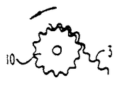
제3도는 상기 지지체가 톱니형 로울상에 감겨지는 것을 도시한 측면도.3 shows a side view of the support being wound on a toothed roll.
* 도면의 주요부분에 대한 부호의 설명* Explanation of symbols for main parts of the drawings
1 : 촉매변환기 지지체 2 : 평탄한 판1 catalytic converter support 2 flat plate
3 : 주름진 판 4 : 중심부3: corrugated plate 4: center
5 : 가장 내부층 8 : 제1용접 연결부5: innermost layer 8: first welded connection
9 : 제2용접 연결부9: second welding connection
본 발명은 평탄한 판과 주름진 판이 교대로 나선형으로 감긴 층 및 주름진 판이 감겨져 있지 않은 부분으로 구성된 중심부로 이루어진 촉매변환기 지지체 또는 그 제조를 위한 모재에 관한 것이다.The present invention relates to a catalytic converter support consisting of a central portion composed of alternating spirally wound layers of flat plates and corrugated plates and portions of which are not wound corrugated plates, or a base material for the manufacture thereof.
소위 초기 촉매변환기에서, 즉 엔진근처에 조립되어서 엔진시동 후에 매우 빠르게 작동온도에 도달되는 촉매변환기는 평탄한 판과 주름진 판이 교대로 나선형으로 감긴 층으로 이루어진 금속지지체가 사용된다는 사실은 잘 알려져 있다. 이때 촉매변환기 지지체 하부의 압력손실을 줄이기 위해서, 중심부는 가능한한 판이 감겨져 있지 않으며, 따라서, 배출가스의 일부가 통과된다. 초기의 촉매변환기는 일반적으로 다른 유해가스의 방출을 줄이는 장치와 함께 사용되기 때문에 이것이 허용될 수 있다.It is well known that in so-called early catalytic converters, that is, catalytic converters that are assembled near the engine and reach operating temperatures very quickly after engine start, a metal support is used which consists of layers of spirally wound flat plates and corrugated plates. In this case, in order to reduce the pressure loss of the lower portion of the catalytic converter support, the central part is not wound as much as possible, and thus a part of the exhaust gas is passed. This is acceptable because early catalytic converters are usually used with devices that reduce the emissions of other harmful gases.
예를들면, 종래의 촉매변환기 지지체는 실린더형 축에 감겨지며, 이때 첫번째 두층은 슬릿의 수단에 의해서 상기 축에 고정되었다. 이러한 방식으로 형성된 종래의 형태는 축을 빼낸뒤에 중심부쪽으로 불규칙하게 돌출되어 있는 내부층의 단부가 있다. 이러한 단부는 촉매변환을 하지 않으면서 배출가스의 통과를 방해한다.For example, a conventional catalytic converter support is wound around a cylindrical shaft, where the first two layers are fixed to the shaft by means of slits. The conventional form formed in this way has an end of the inner layer which protrudes irregularly towards the center after the shaft is pulled out. This end blocks the passage of the exhaust gas without catalytic conversion.
또한, 감김이 실런더형 축에서 수행될때 평탄한 금속판이 가장 내부층으로 사용되며, 이것은 포함된 빠른 순환주기를 고려할때 대량 생산동안에 판의 단부를 고정시키는 것이 어렵다.In addition, when the winding is performed on the cylinder type shaft, a flat metal plate is used as the innermost layer, which makes it difficult to fix the end of the plate during mass production, considering the fast circulation cycle involved.
독일공개공보 DE-OS 25 56 030에는 평탄한 촉매변환기 지지체를 제조하기 위한 모재가 공지되어 있는데, 이것도 마찬가지로 실린더형 축에 감겨진다. 이러한 구조 및 그 제조공정은 감을때 전술한 초기의 촉매 변환기 지지체에서와 동일한 문제점이 있다.In DE-OS 25 56 030, a base material for producing a flat catalytic converter support is known, which is likewise wound around a cylindrical shaft. This structure and its manufacturing process have the same problems as in the earlier catalytic converter support described above.
본 발명의 목적은 판이 감겨져 있지 않은 중심부가 형성되어 있으나 전술한 문제점이 나타나지 않는 촉매 변환기 지지체 또는 그 제조를 위한 모재를 제공하는데 있다.SUMMARY OF THE INVENTION An object of the present invention is to provide a catalytic converter support or a base material for producing the same, in which a central portion having no plate wound is formed but the above-mentioned problems do not appear.
본 발명의 다른 목적은 평탄한 금속판 및 주름진 금속판이 교대로 나선형으로 감긴 층으로 구성되며, 상기 주름진 금속판의 적어도 하나는 가장 내부층으로 둘러싸인 판이 감겨져 있지 않은 부분으로 구성된 중심부를 포함하는 내부층을 형성하는 모재를 제공하는 것이다. 촉매변환기 지지체는 상기 모재주위에 쟈켓을 첨가함으로써 형성된다.Another object of the present invention is to form an inner layer comprising a central metal sheet consisting of a portion of which the flat metal plate and the corrugated metal plate are alternately spirally wound, and wherein at least one of the corrugated metal plate is surrounded by the innermost layer. It is to provide the base material. The catalytic converter support is formed by adding a jacket around the base material.
본 발명은 목적은, 촉매변환기 지지체의 제작에 알맞은 모재를 생산하는 방법을 제공하는 것이며, 상기 방법은 톱니가 주름판의 주름에 거의 상응하는 톱니형 로울상에 나선형으로 주름진 금속판을 감고 실질적으로 평탄한 금속판을 감는 것이다. 지지체를 제작하기 위하여, 쟈켓은 감겨진 주름진 금속판과 평탄한 금속판 주위에 설치된다.It is an object of the present invention to provide a method for producing a base material suitable for the fabrication of a catalytic converter support, wherein the tooth is wound on a serrated corrugated metal plate spirally corresponding to the corrugation of the corrugated plate and is substantially flat. It is winding the metal plate. To fabricate the support, the jacket is installed around the wound corrugated metal plate and the flat metal plate.
본 발명의 특징에 따르면, 가장 내부층은 다수의 상기 주름진 층으로 구성된다.According to a feature of the invention, the innermost layer consists of a plurality of said corrugated layers.
본 발명의 다른 특징은 본 발명에 따라 판이 감겨져 있지 않은 부분으로 구성된 중심부를 둘러싸고 있는 촉매변환기 지지체의 가장 내부층이 주름진 판으로 이루어지고, 가장 내부층의 주름은 나중에 촉매변환기 지지체가 평탄한 형태로 함께 압축되는 경우 문제점을 발생시키지 않고 중심부로 배출가스가 통과하는 것을 방해하지 않는 것이다.Another feature of the present invention is that the innermost layer of the catalytic converter support surrounding the central portion consisting of the unwound portion of the present invention consists of a corrugated plate, and the innermost layer of the corrugation is later joined together in a flat form. When compressed, it does not create a problem and does not interfere with the passage of exhaust gas to the center.
본 발명의 다른 특징에 의하면, 평탄한 금속판 및 주름진 금속판은 두개의 단부면을 구비하며, 상기 층을 서로 결합시키고 또한 상기 쟈켓에 결합시키는 상기 단부면들 중 한 단부면의 제1용접 연결부 및 실질적으로 가장 내부층의 2 내지 10개의 금속판을 서로 용접시키는 상기 단부면들 중 한 단부면에 제2용접 연결부가 제공된다.According to another feature of the invention, the flat metal plate and the corrugated metal plate have two end faces, the first weld connection of substantially one end face of the end faces joining the layers to each other and to the jacket and substantially A second welded connection is provided on one of the end faces which welds the two to ten metal plates of the innermost layer to each other.
본 발명의 다른 특징에 의하면, 상기 제1용접 연결부는 촉매변환기 지지체의 원주에 위치되고 상기 제2용접 연결부는 촉매변환기 지지체의 중심부에 위치된다.According to another feature of the invention, the first welded connection is located at the circumference of the catalytic converter support and the second welded connection is located at the center of the catalytic converter support.
이로인해 쟈켓내에서 촉매변환기 지지체가 신장될 수 있으며, 가장 내부층이 양쪽 용접 연결로 인해 비틀리거나 불안정하게 되지 않는다.This allows the catalytic converter support to be stretched in the jacket and the innermost layer is not twisted or unstable due to both welded connections.
본 발명에 따른 제조방법에서는, 가장 내부층이 실린더형 축에 감겨지지 않고, 톱니가 주름판의 주름에 거의 상응하는 톱니형 로울에 감겨지기 때문에 많은 장점이 있다. 밴드형 주름판이 회전하는 톱니형 로울에 공급되면, 로울은 실제적인 각각의 위치에서 밴드형 주름판을 고정시키고, 감기위해 부가적으로 필요한 인장력을 제공할 수 있다. 따라서 평탄한 또는 주름진 밴드형판의 단부가 축의 슬릿내에 끼워진 필요가 없으며 이로인해 제조시 공정시간이 최소화 될 수 있다. 또한 실린더형 축 대신에 톱니형 로울을 사용하기 때문에 다른 모든 제작단계를 바꿀 필요가 없다는 장점이 있다. 감는것이 끝난뒤에 톱니형 로울은 빼내어지고, 형성된 촉매변환기 지지체 또는 모재는 쟈켓 튜브의 접합, 브레이징, 코팅 등등과 같은 다른 제조단계에 들어간다.In the manufacturing method according to the present invention, there are many advantages because the innermost layer is not wound on the cylindrical shaft, and the teeth are wound on the toothed rolls which almost correspond to the wrinkles of the corrugated plate. When the banded corrugated plate is fed to a rotating toothed roll, the roll can hold the banded corrugated plate at each actual position and provide the additional tension required to wind it. Thus, the end of the flat or corrugated band-like plate does not need to be fitted in the slit of the shaft, thereby minimizing the process time during manufacture. In addition, the use of a toothed roll instead of the cylindrical shaft has the advantage that no other manufacturing steps need to be changed. After winding, the toothed roll is removed and the formed catalytic converter support or substrate enters another stage of manufacture such as joining, brazing, coating, etc. of the jacket tube.
안정성이 필요한 경우에는 평탄한 밴드형판을 부착함으로써 실제적인 벌집구조로 감겨지기 전에, 먼저 두개 또는 다수의 주름진 밴드형판 층이 톱니형 로울에 감겨질 수 있다.If stability is desired, two or more corrugated band plate layers may first be wound on a toothed roll before being wound into a real honeycomb structure by attaching a flat band plate.
축 대신 톱니형 로울을 사용함으로써, 평탄한 밴드형판을 중간층으로 부착시키지 않고 제2 또는 제3주름진 밴드형판 층이 거의 잠금의 형태로 제1판층에 접합될 수 있다. 다수의 층으로 이루어진, 안정된 가장 내부의 주름판은 판의 감김이 없는 중심부를 벌집형 구조체로 부터 분리시키도록 형성된다. 가장 내부층의 단부는 브레이징, 용접 또는 접착과 같은 접합 기술에 의해 부가적으로 고정될 수 있다.By using a toothed roll instead of an axis, the second or third corrugated band plate layer can be bonded to the first plate layer in the form of a lock almost without attaching the flat band plate to the intermediate layer. The stable innermost corrugated plate, made of multiple layers, is formed to separate the unwound core from the honeycomb structure. The ends of the innermost layer may additionally be fixed by joining techniques such as brazing, welding or gluing.
비록 본 발명의 실시예는 금속 촉매변환기 지지체, 상기 지지체를 생산하기 위한 모재, 그리고 상기 생산을 위한 방법의 바람직한 실시예를 예시하고 개시하였지만, 본 발명의 다양한 수정 및 변형은 본 발명의 사상 범위내에서 당업자에 의해서 수행된다.Although embodiments of the present invention illustrate and disclose preferred embodiments of a metal catalytic converter support, a base material for producing the support, and a method for producing the same, various modifications and variations of the present invention are within the spirit of the present invention. It is performed by those skilled in the art.
본 발명의 실시예를 첨부한 도면을 참고로 상세히 설명하면 다음과 같다.When described in detail with reference to the accompanying drawings an embodiment of the present invention.
촉매변환기 지지체(1)는 평탄한 판 금속 스트립(2)과 주름진 판 금속 스트립(3)이 나선형으로 감겨있고, 판의 감김이 없는 부분이 구성되어 있는 중심부(4)가 비어있다. 감김이 없는 부분으로 구성된 중심부(4)는 가장 내부의 주름진 판층(5)으로 둘러 싸여진다. 제2도는 제1도에 사용된 같은 참조번호의 요소가 사용된 촉매변환기 지지체를 나타낸다. 그러나 가장 내부의 주름진 판 금속스트립(6)은 다수의 개개적인 주름판(3)으로 구성된다. 안정성이 필요하고 중심부를 둘러싸는 경계를 좋게하려면, 평탄한 판스트립을 부착함으로써 벌집형 구조체를 구성하기 전에 두개 또는 다수의 주름진 판을 잠금형태로 층을 이루도록 놓을 수 있다.The
상기된 것과 같이, 판(2 및 3)이 감긴후에, 모재의 형태로 생산된 중간층이 형성된다. 쟈켓, 덮개 혹은 튜브(7)은 완성체를 형성하기 위하여 판(2 및 3) 주위에 설치된다.As described above, after the plates 2 and 3 are wound up, an intermediate layer produced in the form of a base material is formed. A jacket, lid or tube 7 is installed around the plates 2 and 3 to form the finished body.
감긴후에, 제1용접 연결부(8)는 층들을 서로와 결합시키고 쟈켓(7)에 결합시키기 위하여 지지체 단부면중 한 단부에 제공되고, 제2용접 연결부(9)는 실질적으로 가장 내부의 2 내지 10개의 층을 서로 용접 결합시키기 위하여 단부면 중 다른 단부에 제공된다. 도면상으로는, 연결부는 판들을 도시하기 위하여 절단되어 있으나, 실제적으로는 완전한 링 혹은 워셔형 구역을 형성한다. 제1용접 연결부(8)는 구역(4)에서 쟈켓(7)까지의 넓은 링을 나타내지만 제2용접 연결부(9)는 상당히 좁은 링을 나타낸다. 제1연결부 및 제2연결부는 도면상에서 간명함을 위해서 지지체의 같은 단부면에 도시되어 있다. 그러나 이들은 실제로 지지체의 반대 단부면에 설치된다.After being wound up, a first welded connection 8 is provided at one end of the support end face for joining the layers to each other and to the jacket 7, and the second welded connection 9 is substantially two to the innermost one. Ten layers are provided at the other end of the end face for welding joining to each other. In the figure, the connection is cut to show the plates, but in practice forms a complete ring or washer-shaped zone. The first welded connection 8 shows a wide ring from the zone 4 to the jacket 7 while the second welded connection 9 shows a fairly narrow ring. The first and second connectors are shown on the same end face of the support for simplicity in the drawings. However, they are actually installed on opposite end faces of the support.
제3도는 주름핀 판(3)이 감김의 초기에 감겨지는 톱니형 로울(10)이 도시되어 있다. 로울(10)의 톱니는 판(3)의 주름과 크기가 일치한다. 주름진 판(3)의 한 층이 감기고 난 후, 평탄한 판(2)의 감김은 제1도에 도시되어 있는 것처럼 모재를 생산하기 위하여 시작된다. 다수의 주름진 판은 제1평탄한 판(2)이 제2도에 도시되어 있는 모재를 생산하기 위하여 첨가되기 전에 감겨진다. 공정이 수행된 후 롤러(10)는 간단히 빠져 나온다.3 shows a
사용되는 판은 매우 얇기 때문에 전술한 제조방법에서는 또다른 장점이 나타난다. 감은 고정에서 언제 평탄한 판스트립을 부착하느냐 하는 것은 중요하지 않다.Since the plate used is very thin, another advantage emerges from the above-described manufacturing method. It is not important when attaching the flat plate strips in the wound fixing.
두번까지의 회전의 차이는 층을 이루어 감겨진 최초의 주름진 판 층의 수를 증가시키기는 하지만 구조체의 전체 직경을 중요하지 않는 밀리미터 정도만 변화시킨다.The difference in rotation up to two times increases the number of layers of the first corrugated plate wound in layers, but only changes the total diameter of the structure by an order of magnitude insignificant.
본 발명에 의해 단부를 끼워넣을 필요가 없고 오류가 현저하게 줄어들기 때문에, 감김이 없는 중심부를 갖는 촉매변환기 지지체를 감는 것이 매우 용이해진다. 따라서 제조공정시 공정시간이 축소될 수 있다. 다른 가공을 할때 선행기술에 비하여 차이점이나 단점이 또한 나타나지 않는다.With the present invention, there is no need to sandwich the end and the error is remarkably reduced, so it is very easy to wind the catalytic converter support having the unwound center. Therefore, the process time in the manufacturing process can be shortened. There are also no differences or disadvantages compared to the prior art when doing other processing.
Claims (8)
Applications Claiming Priority (3)
| Application Number | Priority Date | Filing Date | Title |
|---|---|---|---|
| DE3639597.8 | 1986-11-20 | ||
| DE3639597 | 1986-11-20 | ||
| DEP3639597.8 | 1986-11-20 |
Publications (2)
| Publication Number | Publication Date |
|---|---|
| KR880005964A KR880005964A (en) | 1988-07-21 |
| KR950009713B1 true KR950009713B1 (en) | 1995-08-26 |
Family
ID=6314331
Family Applications (1)
| Application Number | Title | Priority Date | Filing Date |
|---|---|---|---|
| KR1019870013092A KR950009713B1 (en) | 1986-11-20 | 1987-11-20 | Metal support for a catalyst and method for its production |
Country Status (8)
| Country | Link |
|---|---|
| US (1) | US4842954A (en) |
| EP (1) | EP0270856B1 (en) |
| JP (1) | JPS63137756A (en) |
| KR (1) | KR950009713B1 (en) |
| AT (1) | ATE91920T1 (en) |
| DE (1) | DE3786756D1 (en) |
| ES (1) | ES2041670T3 (en) |
| MX (1) | MX169652B (en) |
Families Citing this family (11)
| Publication number | Priority date | Publication date | Assignee | Title |
|---|---|---|---|---|
| ES2014333B3 (en) * | 1987-01-15 | 1990-07-01 | Emitec Ges Fur Emissionstechnologie Mbh | CATALYST SUPPORTING BODY, WITH SHORT COVERED TUBE. |
| JPH0441937Y2 (en) * | 1987-12-28 | 1992-10-02 | ||
| DE3831616A1 (en) * | 1988-09-17 | 1990-03-22 | Sueddeutsche Kuehler Behr | Process for the production of support bodies for catalytic reactors for exhaust gas purification |
| US5135794A (en) * | 1988-09-22 | 1992-08-04 | Emitec Gesellschaft Fur Emissionstechnologie Mbh | Honeycomb body, in particular catalyst carrier body, formed of a plurality of entwined bundles of sheet metal |
| US5057482A (en) * | 1988-12-15 | 1991-10-15 | Matsushita Electric Industrial Co., Ltd. | Catalytic composite for purifying exhaust gases and a method for preparing the same |
| JPH0733875Y2 (en) * | 1989-05-08 | 1995-08-02 | 臼井国際産業株式会社 | Exhaust gas purification device |
| US5846495A (en) * | 1995-07-12 | 1998-12-08 | Engelhard Corporation | Structure for converter body |
| IN187850B (en) * | 1995-08-16 | 2002-07-06 | Emitec Emissionstechnologie | |
| JP3053602B2 (en) | 1997-11-10 | 2000-06-19 | 大平製紙株式会社 | Inner sealing material for sealing the container mouth |
| JP2001179111A (en) * | 1999-10-14 | 2001-07-03 | Nippon Steel Corp | Metallic carrier for automobile exhaust gas cleaning catalyst and its manufacturing method |
| DE102017109191A1 (en) * | 2017-04-28 | 2018-10-31 | Faurecia Emissions Control Technologies, Germany Gmbh | Component of an exhaust system and method for producing such a component |
Family Cites Families (25)
| Publication number | Priority date | Publication date | Assignee | Title |
|---|---|---|---|---|
| DE1097344B (en) * | 1958-09-08 | 1961-01-12 | Corning Glass Works | Process for the production of ceramic objects with honeycomb-like cross-sections |
| US3086625A (en) * | 1959-03-19 | 1963-04-23 | Triar Inc | Cellular core and method of making same |
| FR1421463A (en) * | 1964-11-02 | 1965-12-17 | Ferodo Sa | Catalytic reactor |
| DE2247254A1 (en) * | 1971-09-30 | 1973-04-05 | British Leyland Truck & Bus | CATALYST CARRIER |
| DE2263554A1 (en) * | 1972-01-18 | 1974-07-04 | Feldmuehle Anlagen Prod | CATALYST CARRIER MADE OF SINTERED INORGANIC MATERIAL WITH OUTER SHEATH |
| GB1491206A (en) * | 1973-11-08 | 1977-11-09 | Atomic Energy Authority Uk | Catalyst bodies |
| GB1491198A (en) * | 1974-10-25 | 1977-11-09 | Atomic Energy Authority Uk | Catalyst bodies and methods of manufacturing such bodies |
| US4193793A (en) * | 1974-12-26 | 1980-03-18 | Union Carbide Corporation | Porous metal-alumina composite |
| US3958626A (en) * | 1975-02-21 | 1976-05-25 | General Motors Corporation | Regenerator matrix structure |
| DE2733640C3 (en) * | 1977-07-26 | 1981-04-30 | Süddeutsche Kühlerfabrik Julius Fr. Behr GmbH & Co KG, 7000 Stuttgart | Matrix for a catalytic reactor for exhaust gas cleaning in internal combustion engines |
| DE2754776C3 (en) * | 1977-12-08 | 1981-10-22 | Messer Griesheim Gmbh, 6000 Frankfurt | Method for producing a honeycomb sheet metal structure |
| US4221843A (en) * | 1978-06-26 | 1980-09-09 | Matthey Bishop, Inc. | Construction of elliptical metal substrates |
| DE2856030A1 (en) * | 1978-12-23 | 1980-06-26 | Sueddeutsche Kuehler Behr | CARTRIDGE FOR EXHAUST GAS PURIFICATION |
| US4239834A (en) * | 1978-12-29 | 1980-12-16 | Matthey Bishop Incorporated | Metal substrate formation with torx recess mandrel |
| US4394422A (en) * | 1981-06-08 | 1983-07-19 | Ray J. Van Thyne | Bonded structure and process of making same |
| US4576800A (en) * | 1984-09-13 | 1986-03-18 | Camet, Inc. | Catalytic converter for an automobile |
| DE8438260U1 (en) * | 1984-12-29 | 1985-04-11 | Süddeutsche Kühlerfabrik Julius Fr. Behr GmbH & Co KG, 7000 Stuttgart | CARRIER MATRIX, ESPECIALLY FOR A CATALYTIC REACTOR FOR EXHAUST GAS PURIFICATION |
| DE3515681A1 (en) * | 1985-05-02 | 1986-11-06 | Üründül, Celâl, 6800 Mannheim | Metal support in a single-foil design |
| DE3527111A1 (en) * | 1985-07-29 | 1987-01-29 | Interatom | METAL, WINDED EXHAUST GAS CATALYST SUPPORT BODY WITH A GEOMETRICALLY COMPLEX FORM OF THE CROSS-SECTION, AND METHOD, DEVICE AND ROLLING FOR ITS PRODUCTION |
| US4598063A (en) * | 1985-08-09 | 1986-07-01 | Retallick William B | Spiral catalyst support and method of making it |
| DE3530893A1 (en) * | 1985-08-29 | 1987-03-05 | Interatom | GROWTH COMPENSATING METALLIC EXHAUST GAS CATALYST SUPPORT BODY AND SHEET FOR ITS PRODUCTION |
| ATE47199T1 (en) * | 1985-10-25 | 1989-10-15 | Interatom | PROCESS FOR BRAZING METALLIC CATALYST SUPPORTS. |
| DE3640025A1 (en) * | 1985-11-26 | 1987-05-27 | Toyota Motor Co Ltd | MONOLITHIC CATALYST CARRIER AND MONOLITHIC CATALYST FOR USE TO CLEAN EXHAUST GAS |
| DE3601011A1 (en) * | 1986-01-15 | 1987-07-16 | Interatom | METAL CATALYST BODY WITH HEAT RADIATION PROTECTION |
| JP2966418B2 (en) * | 1988-09-06 | 1999-10-25 | ソニー株式会社 | Method of forming wiring contact |
-
1987
- 1987-11-09 AT AT87116531T patent/ATE91920T1/en not_active IP Right Cessation
- 1987-11-09 ES ES198787116531T patent/ES2041670T3/en not_active Expired - Lifetime
- 1987-11-09 DE DE8787116531T patent/DE3786756D1/en not_active Expired - Lifetime
- 1987-11-09 EP EP87116531A patent/EP0270856B1/en not_active Expired - Lifetime
- 1987-11-16 JP JP62289235A patent/JPS63137756A/en active Granted
- 1987-11-20 KR KR1019870013092A patent/KR950009713B1/en not_active IP Right Cessation
- 1987-11-20 US US07/123,386 patent/US4842954A/en not_active Expired - Lifetime
- 1987-11-23 MX MX009435A patent/MX169652B/en unknown
Also Published As
| Publication number | Publication date |
|---|---|
| ES2041670T3 (en) | 1993-12-01 |
| EP0270856B1 (en) | 1993-07-28 |
| JPH0463738B2 (en) | 1992-10-12 |
| ATE91920T1 (en) | 1993-08-15 |
| KR880005964A (en) | 1988-07-21 |
| JPS63137756A (en) | 1988-06-09 |
| DE3786756D1 (en) | 1993-09-02 |
| EP0270856A1 (en) | 1988-06-15 |
| US4842954A (en) | 1989-06-27 |
| MX169652B (en) | 1993-07-16 |
Similar Documents
| Publication | Publication Date | Title |
|---|---|---|
| US6751864B2 (en) | Process and apparatus for producing a metallic honeycomb body | |
| KR950009713B1 (en) | Metal support for a catalyst and method for its production | |
| US4559205A (en) | Catalytic converter substrate and retainer assembly | |
| US6158120A (en) | Method for making a catalytic converter containing a multiple layer mat | |
| US4629605A (en) | Device for catalytically purifying exhaust gases for a combustion engine | |
| JPH10121953A (en) | Method of manufacturing catalyst converter used in internal combustion engine | |
| US5336472A (en) | Honeycomb structure for purifying exhaust gas and method of manufacturing same | |
| JPH04227855A (en) | Metal carrier matrix for catalyst reactor | |
| US20070026252A1 (en) | Metallic honeycomb structure | |
| JP2634669B2 (en) | Metal honeycomb catalyst device | |
| JPH08309206A (en) | Production of carrier of metal catalyst for purifying waste gas | |
| US5173471A (en) | Exhaust gas cleaning device | |
| JP3677053B2 (en) | Monolithic metal carrier catalyst and exhaust gas purification method | |
| KR100572903B1 (en) | Method and sheet metal pile for producing a honeycomb body with a plurality of channels through which a fluid is able to flow | |
| JP4097693B2 (en) | Equipment with a honeycomb body | |
| JPH06254410A (en) | Catalyst carrier for exhaust emission control device | |
| FI104202B (en) | Honeycomb structure for a catalyst | |
| JP3308075B2 (en) | Manufacturing method of heat-resistant structure | |
| JP2002295249A (en) | Catalytic converter | |
| JP2746193B2 (en) | Catalyst support bracket, seal / support bracket using the same, and method of manufacturing catalyst support bracket | |
| JPH04150948A (en) | Metal carrier supporting exhaust gas purifying catalyst having intermittently bonded honeycomb part and preparation thereof | |
| JP2577571B2 (en) | Method for producing base for supporting exhaust gas purifying catalyst | |
| JPH06277527A (en) | Segment type catalyst carrier for exhaust gas purification device and production therefor | |
| JP2001205354A (en) | Manufacturing method of treatment apparatus for gas | |
| JPH0523775Y2 (en) |
Legal Events
| Date | Code | Title | Description |
|---|---|---|---|
| A201 | Request for examination | ||
| G160 | Decision to publish patent application | ||
| E701 | Decision to grant or registration of patent right | ||
| GRNT | Written decision to grant | ||
| FPAY | Annual fee payment |
Payment date: 20070724 Year of fee payment: 13 |
|
| LAPS | Lapse due to unpaid annual fee |