KR940001962B1 - Panel conservence device for color crt fluorescent flat - Google Patents
Panel conservence device for color crt fluorescent flat Download PDFInfo
- Publication number
- KR940001962B1 KR940001962B1 KR1019910001247A KR910001247A KR940001962B1 KR 940001962 B1 KR940001962 B1 KR 940001962B1 KR 1019910001247 A KR1019910001247 A KR 1019910001247A KR 910001247 A KR910001247 A KR 910001247A KR 940001962 B1 KR940001962 B1 KR 940001962B1
- Authority
- KR
- South Korea
- Prior art keywords
- panel
- color crt
- antistatic
- frame
- conservence
- Prior art date
Links
Images


Classifications
-
- H—ELECTRICITY
- H01—ELECTRIC ELEMENTS
- H01J—ELECTRIC DISCHARGE TUBES OR DISCHARGE LAMPS
- H01J9/00—Apparatus or processes specially adapted for the manufacture, installation, removal, maintenance of electric discharge tubes, discharge lamps, or parts thereof; Recovery of material from discharge tubes or lamps
- H01J9/38—Exhausting, degassing, filling, or cleaning vessels
Abstract
내용 없음.No content.
Description
제1도는 본 발명의 한 실시예를 도시하는 사시도.1 is a perspective view showing one embodiment of the present invention.
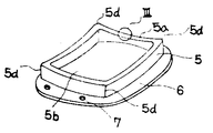
제2도는 본 발명에 따르는 보호 커버를 도시하는 사시도.2 is a perspective view showing a protective cover according to the present invention.
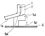
제3도는 제2도의 Ⅲ부의 확대 단면도.3 is an enlarged cross-sectional view of part III of FIG.
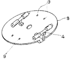
제4도는 패널 장착부를 도시하는 사시도.4 is a perspective view showing a panel mount.
제5도는 패널 플루오로산 세정부를 도시하는 개략도.5 is a schematic diagram showing a panel fluoroacid cleaning.
제6도는 대전 방지용 패널을 도시하는 사시도.6 is a perspective view showing an antistatic panel.
* 도면의 주요부분에 대한 부호의 설명* Explanation of symbols for main parts of the drawings
1 : 패널 1a : 패널 바닥면1: Panel 1a: Panel Bottom
5 : 프레임 5a : 패널 밀착면5:
[산업상 이용분야][Industrial use]
본 발명은 컬러 브라운관 형광면용 패널 보존 장치에 관한 것이다.The present invention relates to a panel storage device for color CRT fluorescent surfaces.
[종래의 기술][Prior art]
종래의 대전 방지용 패널을 플루오로산(弗酸) 세정부에서 세정할 때는 패널 바닥면 및 스커트부의 한가운데까지 수지제 시트로 커버하거나, 혹은 각 크기마다 전용의 고무제 보호 커버를 사용하는 방법을 이용하고 있었다. 즉, 작업자가 각각의 패널마다 시트 커버를 하거나, 전용의 고무제 보호 커버를 사용하여 세정 공정 동안에 플루오로산의 튀김으로 인한 패널 바닥면 등의 외관 불량을 방지하고 있었다.When cleaning the conventional antistatic panel with a fluoroacid cleaning unit, cover with a resin sheet to the middle of the panel bottom and skirt or use a rubber protective cover for each size. Was doing. That is, the worker covered the sheet for each panel or used a dedicated rubber protective cover to prevent appearance defects such as the bottom surface of the panel due to the splash of fluoroacid during the cleaning process.
[고안이 해결하려는 과제][A challenge to solve]
상술한 종래의 방법에서는 플루오로산 세정중에 패널과 시트 커버 사이에 플루오로산이 침투하기 쉽고, 패널의 대전 방지용막이 손상되어 외관이 불량하게 되는 경우가 있었다. 작업자는 또한 패널마다 시트 커버를 장착하지 아니하면 아니되므로 번거로워진다. 또한, 전용의 보호 커버를 사용한 경우에 그 커버를 사용하는 패널의 크기에 제한이 있으며, 자동기계로 실제 다종.양산 체제에 대처하기에는 적절하지 못한 결점이 있었다.In the conventional method described above, fluoroacids easily penetrate between the panel and the seat cover during fluoroacid cleaning, and the antistatic film of the panel may be damaged, resulting in poor appearance. The operator is also cumbersome since it is not necessary to install seat covers for each panel. In addition, when a dedicated protective cover is used, there is a limitation on the size of the panel using the cover, and there is a defect that is not appropriate to cope with the actual multi-purpose and mass production system by an automatic machine.
본 발명의 목적은 상기 과제를 해결한 패널 보존 장치를 제공하는 것이다.An object of the present invention is to provide a panel storage device that solves the above problems.
[과제를 해결하기 위한 수단][Means for solving the problem]
상기 목적을 달성하기 위하여, 본 발명에 따르는 컬러 브라운관용 형광면의 제조 장치에 사용하는 패널 보존 장치는 한쪽 단면이 개방된 구조의 프레임을 포함하며, 상기 프레임은 개구 가장자리를 대전 방지용 패널의 바닥면의 외주 가장자리에 접촉시켜 상기 이 패널의 바닥면을 피복하여 기밀 밀봉하고, 상기 프레임은 그 개구 가장자리로 탄성 변형하므로써 크기가 다른 대전 방지용 패널의 바닥면 외주 가장자리에 서로 밀착하는 패널 밀착면을 갖는다.In order to achieve the above object, the panel preservation apparatus for use in the apparatus for producing a fluorescent screen for color CRT tubes according to the present invention includes a frame having a structure in which one end surface is open, the frame having an opening edge of the bottom surface of the antistatic panel. The panel is hermetically sealed by covering the bottom surface of the panel by being in contact with an outer circumferential edge, and the frame has a panel-adhering surface that closely adheres to the bottom circumferential edges of the antistatic panel having different sizes by elastically deforming to the opening edge.
[실시예]EXAMPLE
다음에, 본 발명의 한 실시예를 도면에 의해 설명한다.Next, an embodiment of the present invention will be described with reference to the drawings.
제1도는 본 발명의 한 실시예를 도시하는 사시도이며, 제2도는 본 발명에 따르는 보호 커버를 도시하는 사시도이며, 제3도는 제2도의 Ⅲ부 확대 단면도이며, 그리고 제4도는 패널 장착부를 도시하는 사시도이다.FIG. 1 is a perspective view showing one embodiment of the present invention, FIG. 2 is a perspective view showing a protective cover according to the present invention, FIG. 3 is an enlarged sectional view of part III of FIG. 2, and FIG. 4 shows a panel mounting part. It is a perspective view.
제6도에 도시하는 바와 같이 대전방지용 패널(1)은 패널 바닥면(1a)과, 패널 바닥면(1a)의 끝 가장자리에 세워진 스커트부(1b)를 갖고, 패널 바닥면(1a)과 대향하는 단면이 개방되어 있으며 패널 바닥면(1a)의 외면에는 대전 방지용 막이 코팅되어 있다.As shown in FIG. 6, the antistatic panel 1 has a panel bottom face 1a and a skirt portion 1b erected at the end edge of the panel bottom face 1a, and faces the panel bottom face 1a. The cross section is opened and an antistatic film is coated on the outer surface of the panel bottom surface 1a.
본 발명은, 대전 방지용 패널(1)의 패널 바닥면(1a)에 플루오로산이 부착되는 것을 방지하고 또한 자동기계로 다종.양산체제에 대처하기 위해, 패널 곡률 칫수와 거의 일치하는 개구 가장자리(5b)를 갖는 내부 중공 구조의 고무제 프레임(5)을 금형으로 제작하고 있다. 프레임(5)의 개구 가장자리(5b)에 형성되는 패널 밀착면(5a)에는 부드러운 고무를 사용하고 있으며, 상기 패널 밀착면(5a)은 크기가 다른 패널(1, 1')의 패널 바닥면(1a)의 외주 가장자리에 서로 각각 밀착하도록 확대된다.In order to prevent the fluoroacid from adhering to the panel bottom surface 1a of the antistatic panel 1, and to cope with various kinds of mass production systems, the
그런데, 패널(1, 1')의 패널 바닥면(1a)의 패널 곡률은 크기마다 다르기 때문에, 패널 바닥면(1a)과 패널 밀착면(5a) 사이에 틈이 생긴다. 따라서, 정방형의 프레임(5)의 모서리부분(5d)에 절결부(5c)를 형성하여 패널 밀착면(5a)이 패널 바닥면(1a)에 서로 양호하게 밀착하도록 탄성을 제공할 수 있다. 또한 프레임(5)과 금속판(6)은 열처리 접착되고, 금속판(6)에는 부착 구멍(7)이 설치되어 있다.By the way, since the panel curvature of the panel bottom surface 1a of the panels 1 and 1 'differs for every size, a gap arises between the panel bottom surface 1a and the
제4도는 제2도에 도시한 보호 커버가 나사 체결되는 패널 장착부로서, 기판(3)에는 제2도에 도시한 금속판(6)에 설치된 부착 구멍(7)과 대응하는 위치에 부착 구멍(9)이 설치되어 있다. 또한, 기판(3)에는 제6도의 패널(1)의 스커트부(1b)를 부착 고정하는 클램프 아암(4)이 설치되어 있다. 기판(3)은 제5도에 도시하는 바와 같이 세정용 헤드(8)에 부착된다.4 is a panel mounting portion in which the protective cover shown in FIG. 2 is screwed in, and the
대전 방지용 패널(1)의 세정에서는 우선 제2도의 보호 커버를 제4도의 패널 장착부에 부착한다. 부착시에는 기판(3)의 중심에 프레임(5)의 중심이 일치하도록 위치를 결정한다. 이에 의해 금속판(6)에 있는 부착 구멍(7)과 기판(3)에 있는 부착 구멍(9)과의 위치가 일치되기 때문에 부착 구멍(7)에 나사를 삽입시켜 부착 구멍(9)에 나사 결합한다. 다음에 제1도에 도시된 것처럼, 프레임(5)의 패널 밀착면(5a)에 대전 방지용 패널(1)의 패널 바닥면(1a)의 외주 가장자리를 일치시켜 클램프 아암(4)에 의해 패널(1)의 스커트부(1b)를 부착 고정한다.In cleaning of the antistatic panel 1, the protective cover of FIG. 2 is first attached to the panel mounting part of FIG. At the time of attachment, the position is determined so that the center of the
따라서 대전 방지용 패널(1)은 보호 커버(제2도) 및 패널 장착부(제4도)를 거쳐 헤드(8)에 부착된다. 이 상태에서는 제5도에서 처럼 세정조(10)내의 패널(1)이 하향으로 유지된다. 그리고 패널(1)은 헤드(8)에 의해 회전되고 또한 펌프(P)에 의해 세종조(10)내의 플루오로산(11)을 패널(1)의 내면에 토출시키면서 플루오로산 세정을 실행한다.Thus, the antistatic panel 1 is attached to the head 8 via a protective cover (FIG. 2) and a panel mounting portion (FIG. 4). In this state, the panel 1 in the
본 발명에 의하면, 1대의 프레임(5)에 크기가 다른 패널(1, 1')을 장착하여 패널(1)의 패널 바닥면(1a)을 기밀 보존할 수 있게 된다.According to the present invention, the panel 1, 1 'having different sizes can be attached to one
[발명의 효과][Effects of the Invention]
상술한 바와 같이 본 발명은 프레임에 따른 크기의 대전 방지용 패널을 설치하므로써, 여러 종류의 대전 방지용 패널을 자동기로 사용할 수 있으므로 다종.양산 체제가 가능하게 된다. 또한, 프레임의 패널 밀착면에 탄성을 갖게 하였으므로, 대전 방지용 패널은 프레임의 패널 밀착면에 밀착되어 세정중에 플루오로산액이 튀거나 침투하지 아니하므로, 종래와 비교하여 외관불량이 없다.As described above, according to the present invention, by providing an antistatic panel having a size corresponding to a frame, various kinds of antistatic panels can be used as an automatic machine, thereby enabling various types and mass production systems. In addition, since the panel adhesion surface of the frame is elastic, the antistatic panel adheres to the panel adhesion surface of the frame so that the fluoroacid solution does not splash or penetrate during cleaning, resulting in no appearance defects as compared with the prior art.
Claims (1)
Applications Claiming Priority (2)
| Application Number | Priority Date | Filing Date | Title |
|---|---|---|---|
| JP8373 | 1990-01-31 | ||
| JP1990008373U JPH0754913Y2 (en) | 1990-01-31 | 1990-01-31 | Panel holding device |
Publications (2)
| Publication Number | Publication Date |
|---|---|
| KR910014979A KR910014979A (en) | 1991-08-31 |
| KR940001962B1 true KR940001962B1 (en) | 1994-03-12 |
Family
ID=11691432
Family Applications (1)
| Application Number | Title | Priority Date | Filing Date |
|---|---|---|---|
| KR1019910001247A KR940001962B1 (en) | 1990-01-31 | 1991-01-25 | Panel conservence device for color crt fluorescent flat |
Country Status (2)
| Country | Link |
|---|---|
| JP (1) | JPH0754913Y2 (en) |
| KR (1) | KR940001962B1 (en) |
-
1990
- 1990-01-31 JP JP1990008373U patent/JPH0754913Y2/en not_active Expired - Lifetime
-
1991
- 1991-01-25 KR KR1019910001247A patent/KR940001962B1/en not_active IP Right Cessation
Also Published As
| Publication number | Publication date |
|---|---|
| KR910014979A (en) | 1991-08-31 |
| JPH0754913Y2 (en) | 1995-12-18 |
| JPH03100346U (en) | 1991-10-21 |
Similar Documents
| Publication | Publication Date | Title |
|---|---|---|
| US7229000B2 (en) | Adjustable frame fixture | |
| US5609496A (en) | Air-tight connector assembly | |
| KR940001962B1 (en) | Panel conservence device for color crt fluorescent flat | |
| CN1065707C (en) | Dustproof structure for electronic apparatus having display portion | |
| US5429697A (en) | Method of sealing a module | |
| CN105807560A (en) | Dust-proof thin-film component container | |
| JP2503806Y2 (en) | Environment-resistant cover structure of display terminals | |
| US7862673B2 (en) | System and method for sealing a telephone handset | |
| US20230182452A1 (en) | A visible part having a layer structure for an operating part or a decorative trim with better protection as a result of a protective paint coating | |
| JPH07122861A (en) | Case body for electronic control apparatus | |
| JPH05308075A (en) | Plating device of semiconductor wafer | |
| JP2509880Y2 (en) | Waterproof structure of electronic circuit unit | |
| US20210114367A1 (en) | Apparatus and process for t-shirt/garment screen printing | |
| JPH07301336A (en) | Mounting method for gasket | |
| JP2001334187A (en) | Masking device for plastic part coating, and masking method of plastic part | |
| JPH0210119Y2 (en) | ||
| JP3508084B2 (en) | Jig for surface defect inspection | |
| CN117282570A (en) | Paint spraying protection assembly and protection method | |
| JP3251683B2 (en) | How to paint the fuel lid | |
| US20040156998A1 (en) | Method for preventing light guide plate from being distorted | |
| JPH0140008Y2 (en) | ||
| JPH0997529A (en) | Electric component mounting device | |
| JPH0323611Y2 (en) | ||
| KR0125905B1 (en) | Resin jig for setting panel and manufacturing method of the | |
| JPH0525273Y2 (en) |
Legal Events
| Date | Code | Title | Description |
|---|---|---|---|
| A201 | Request for examination | ||
| E902 | Notification of reason for refusal | ||
| G160 | Decision to publish patent application | ||
| E701 | Decision to grant or registration of patent right | ||
| GRNT | Written decision to grant | ||
| FPAY | Annual fee payment |
Payment date: 20020307 Year of fee payment: 9 |
|
| LAPS | Lapse due to unpaid annual fee |