KR940000140B1 - Thermal flowmeter - Google Patents
Thermal flowmeter Download PDFInfo
- Publication number
- KR940000140B1 KR940000140B1 KR1019870005288A KR870005288A KR940000140B1 KR 940000140 B1 KR940000140 B1 KR 940000140B1 KR 1019870005288 A KR1019870005288 A KR 1019870005288A KR 870005288 A KR870005288 A KR 870005288A KR 940000140 B1 KR940000140 B1 KR 940000140B1
- Authority
- KR
- South Korea
- Prior art keywords
- conduit
- sensor
- pair
- sensor coils
- wound around
- Prior art date
Links
Images


Classifications
-
- G—PHYSICS
- G01—MEASURING; TESTING
- G01F—MEASURING VOLUME, VOLUME FLOW, MASS FLOW OR LIQUID LEVEL; METERING BY VOLUME
- G01F1/00—Measuring the volume flow or mass flow of fluid or fluent solid material wherein the fluid passes through a meter in a continuous flow
- G01F1/68—Measuring the volume flow or mass flow of fluid or fluent solid material wherein the fluid passes through a meter in a continuous flow by using thermal effects
- G01F1/684—Structural arrangements; Mounting of elements, e.g. in relation to fluid flow
- G01F1/6847—Structural arrangements; Mounting of elements, e.g. in relation to fluid flow where sensing or heating elements are not disturbing the fluid flow, e.g. elements mounted outside the flow duct
Abstract
내용 없음.No content.
Description
제1도 내지 제3도는 본 발명의 1실시예를 표시하며,1 to 3 show an embodiment of the present invention,
제1도는 한편의 블록체를 떼어낸 상태의 사시도.1 is a perspective view of a state in which one block body is removed.
제2도는 측단면도.2 is a side cross-sectional view.
제3도는 센서코일의 감아설치한 상태를 표시한 단면도.3 is a cross-sectional view showing a wound state of the sensor coil.
제4도는 본 발명의 다른 실시예를 표시한 블록체의 사시도.4 is a perspective view of a block body showing another embodiment of the present invention.
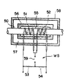
제5도는 종래 기술을 설명하기 위한 단면도.5 is a cross-sectional view for explaining the prior art.
* 도면의 주요부분에 대한 부호의 설명* Explanation of symbols for main parts of the drawings
1 : 센서케이스 2 : 블록체1: sensor case 2: block
4 : 지지돌기체 6 : 도관4: support protrusion 6: conduit
10 : 센서코일10: sensor coil
본 발명은 열식 유량계에 관한 것이다.The present invention relates to a thermal flow meter.
종래의 이 종류의 유량계의 하나는 예컨대 일본국 특공소 60-50289호 공보에 개시되어 있는 바와 같은 것이 있다.One of the conventional flowmeters of this kind is one disclosed in, for example, Japanese Unexamined Patent Application Publication No. 60-50289.
제5도는 상기 유량계의 개략을 나타내고, 이 유량계는 내부에 피측정 유체가 흐르는 도관(50)의 바깥 돌레면에 감열저항선으로 이루어진 센서코일(51,52)을 두루감아, 이 센서코일(51,52) 및 저항(53,54)을 각각 1변으로 하는 브리지회로(WS)를 구성하여, 센서코일(51,52)의 바깥쪽에 이 센서코일(51,52)을 포함한 제1의 밀폐공간(55)을 형성하여 열 양도체로 이루어진 포위체(56 ; 泡圍體)를 도관(50)에 연결합시켜서 장착시키는 동시에, 포위체(56)에 대하여 제2의 밀폐공간(57)에 설치하여 외위체(58 ; 外圍體)를 도관(50)에 장착하여, 제1의 밀폐공간(55), 제2의 밀폐공간(57)에 대류방지수단을 설치, 브리지회로(WS)의 평형상태로 부터의 편이(偏移)에 의거하여 도관(50)내를 흐르는 유체 유량을 측정하도록 한 것이다. 또한 59는 출력단자이다.5 shows an outline of the flow meter, which winds the sensor coils 51 and 52 made up of thermal resistance wires on the outer ridge surface of the
상기한 바와 같이 구성된 유량계에 있어서는 센서코일(51,52)의 주변에 설치된 포위체(56) 및 대류방지 수단을 강구한 밀폐공간(56,57)에 의하여, 센서코일(51,52) 주변의 열적안정이 도모되어, 따라서 외부온도의 변화가 센서코일(51,52)에 영향을 미치는 일없이 그리고 유량계의 장착등에 다소의 경사가 있다고 해도, 유량계 내부의 열의 대류가 방지되므로, 센서코일(51,52)은 안정된 온도환경하에서 작동할 수가 있으며, 정확한 유량측정이 가능하게 된다는 이점을 가진다.In the flowmeter configured as described above, the
그러나, 상기 종래기술에는 다음과 같은 결점이 있다.However, the prior art has the following drawbacks.
일반적으로 이 종류의 유량계는 반도체 제조에 사용되는 가스의 공급로에 설치되는 일이 많으나, 장기간 사용함에 따라 도관내벽에 상기 가스중에 포함되어 있는 고비등점 물질이 부착하는 일이 있기 때문에, 수시로 필요에 따라 도관내에 질소가스등의 불활성 가스를 흘리거나, 혹은 감압하면서 베이크 아웃(bake out)하여 상기 고비등점 물질을 제거할 필요가 있다. 이 베이크 아웃은 예를들면 상응하는 도관을 포함한 케이스이 바깥둘레면에 리본 히이터(ribbon heater)를 감거나, 또는 어떤 설정온도 이상으로 되면 급히 저항치가 증가하는 정(正)의 저항온도 계수를 갖는 자기 온도제어식 저항체로 구성된 히이터(예를들면 무라다 세이사꾸쇼제 「포지스타」(상품명))을 밀착시키는 등 도관을 소정의 온도에까지 가열하므로써 행하여진다.Generally, this type of flowmeter is often installed in the gas supply path used for semiconductor manufacturing, but the high boiling point material contained in the gas adheres to the inner wall of the conduit with long-term use. Therefore, it is necessary to remove the high boiling point material by flowing an inert gas such as nitrogen gas into the conduit or baking out while reducing the pressure. This bake-out is made of, for example, a magnet with a positive temperature coefficient of resistance, in which the case containing the corresponding conduit is wound around a ribbon heater on the outer circumferential surface or, if the temperature rises above a certain set temperature, the resistance increases rapidly. This is performed by heating the conduit to a predetermined temperature, for example, by bringing a heater composed of a temperature-controlled resistor (for example, "Posuta" (trade name) manufactured by Murada Seisakusho) into close contact.
그러나, 이 제5도에 표시하는 바와 같이 종래기술에 있어서는 도관(50)을 포위체(56)와 이 포위체(56)와는 별도의 외위체(58)에 의하여 피복하도록 되어 있기 때문에, 외위체(58)의 바깥둘레에 예를들면, 리본히이터를 감아서 이것을 가열하여도 도관(50)에는 포위체(56)가 열적으로 결합되어 있기 때문에, 도관(50)의 온도가 베이크 아웃에 필요한 온도에 도달하기 까지에는 어느 정도의 시간을 필요하며, 단시간에 효율이 좋게 베이크 아웃하는 것이 곤란하다. 또 도관(50) 및 이것에 두루감인 센서코일(51,52)을 포위체(56) 및 외위체(58)에 의하여 이중으로 포위하는 구조임으로, 가공성이 나쁘며 생산원가가 비싸게 되는 외에도 리이드선을 꺼내는 구조등이 복잡하게 된다는 문제점이 있다.However, as shown in FIG. 5, in the prior art, the
본 발명은 상술한 사항에 유의하여 이루어진 것으로 그 목적하는 바는 베이크 아웃을 단시간에 확실하게 행할수 있으며, 구조가 간단하므로 조립 따위를 용이하게 행할 수가 있는 열식 유량계를 제공하는데 있다.SUMMARY OF THE INVENTION The present invention has been made in consideration of the above-described matters, and its object is to provide a thermal flowmeter that can reliably bake out in a short time and can be easily assembled because of its simple structure.
상술한 목적을 달성하기 위하여 본 발명에 관한 열식 유량계는 내부에 유체가 흐르는 도관의 바깥 둘레면에 한쌍의 센서코일을 감아설치한 열식 유량계에 있어서 열전도성의 재질로 구성된 2개의 블록체에 의하여 센서케이스를 형성하여, 상기 블록체의 적어도 한쪽의 내면에 센서코일의 양끝에 근접하여 한쌍의 지지돌기체를 상기 블록체와 일체적으로 형성하여, 상기 도관을 상기 지지돌기체에 의하여 지지토록한 점에 특징이 있다.In order to achieve the above object, the thermal flowmeter according to the present invention includes a sensor case formed by two block bodies made of a thermally conductive material in a thermal flowmeter having a pair of sensor coils wound around an outer circumferential surface of a conduit through which fluid flows. A pair of support protrusions integrally with the block body at both ends of the sensor coil on at least one inner surface of the block body to support the conduit by the support protrusion body. There is a characteristic.
다음 본 발명의 실시예를 도면을 참조하면서 설명한다.Next, embodiments of the present invention will be described with reference to the drawings.
제1도, 제2도에 있어서 1은 결합분할이 가능한 모양으로 서로 대칭인 형상을 갖는 2개의 블록체(2,2)로된 센서케이스이다.In FIG. 1 and FIG. 2, 1 is the sensor case which consists of two
3은 블록체(2,2)의 접합면에 덧붙이는 은(銀)등을 함유한 에폭시 수지등의 전열성 접착제이다.3 is heat-transfer adhesives, such as an epoxy resin containing silver etc. which add to the joint surface of the
블록체(2,2)의 내면에는 각각 적절한 간격을 두고 한쌍의 지지돌기체(4,4)가 블록체(2,2)와 일체적으로 형성되어 있다.On the inner surface of the
5는 지지돌기체(4,4)사이를 열적으로 교락(橋絡)하는 바와 같이 블록체(2)에 형성되는 교락부이다. 즉 블록체(2,2)의 어느 내면에도 블록체(2,2)와 일체적으로 지지돌기체(4,4) 및 교락부(5)가 형성되어 있다. 그리고 지지돌기체(4,4)의 상면에는 후술하는 도관(6)을 지지하기 위한 오목부(7,7)가 형성되어 있다.5 is an entanglement formed in the
상기 센서케이스(1)는 알루미늄, 스테인레스등의 금속 또는 은의 분말을 섞어 넣은 에폭시 수지등 열전도성이 우수한 재질로 구성된다.The sensor case 1 is made of a material having excellent thermal conductivity, such as an epoxy resin containing a metal or silver powder such as aluminum, stainless or the like.
도관(6)는 대략 역 U자형으로 형성된 스테인레스 등의 금속관으로 이루어지고, 그 양끝(6a,6b)이 스테인레스등의 베이스(8,8)을 꿰어 통한 상태에서 상기 오목부(7,7)에 끼워 넣어져 지지되어, 그 내부를 측정 대상인 유체가 화살표 a 방향으로 흐른다. 9,9는 도관(6)과 지지돌기체(4)와의 열적 결합을 보다 긴밀하게 하기 위해 설치되는 은등을 포함한 에폭시 수지등의 전열성 접착제이다.The
10,10은 도관(6)의 지지돌기체(4,4) 사이의 도관(6)의 바깥 둘레면에 감아 설치되는 한쌍의 센서코일로, 제3도에 표시한 바와 같이 그감기 시작한 위치 및 감기가 끝난위치(예를들면 10a, 10b는 감기시작한 측, 10b, 10b는 감기가 끝난측을 표시)가 양 센서코일(10,10)의 중간 위치에 오도록, 그리고 각각의 끝부분을 3회 반환하여 4층 구조로 감아 설치된다. 그리고, 각 센서코일(10,10)은 도관(6)과는 열적으로 결합되어(전기적으로는 절연되어 있다) 그 지지돌기체(4,4)측의 끝부분은 이 지지돌기체(4,4)에 가급적 근접하도록 설치된다. 이들의 센서코일(10,10)은 이를테면 Fe-Ni 등의 감열저항체로 이루어지며, 도면밖의 2개의 저항소자와 브리지 회로를 형성하도록 접속되어 있다. 또한 제3도에 있어서, 11은 상기한 바와 같이 감아 설치된 센서코일(10,10)을 고정하여, 풀리는 것을 방지하기 위해 센서코일(10,10)을 피복하는 바와 같이 설치되는 실리콘 니스(Varnish) 또는 폴리이미드계 니스 등으로 된 피복층이다.10 and 10 are pairs of sensor coils which are wound around the outer circumferential surface of the
12는 예를들면 세라믹 또는 폴리이미드계 또는 폴리아미드계 수지등의 내열성재료로 구성된 리이드대로, 그 한쪽면에는 금속피복처리에 의하여 복수의 도전부(13)…가 형성되어 있다.12 is a lead made of heat-resistant material such as ceramic or polyimide-based or polyamide-based resin, and on one side thereof, a plurality of
14…는 센서코일(10,10)의 양끝의 감기 시작한 측(10a)…감기가 끝난측(10b)…에 각각 접속되는 리이드선, 15…는 외부 리이드선이다.14... Is the
16은 한쪽(제1도에 있어서 아랫쪽만이 개방되어 그외의 3면이 둘러싸인 내부공간(17)에 설치되는 석영울(wool)과 같은 단열재로, 지지돌기체(4,4) 사이의 도관(6) 및 이 도관(6)에 감아 설치되는 한쌍의 센서코일(10,10)의 주변에 충전되어 있다. 18,18은 베이스(8,8)의 하단면에 형성된 홈안에 설치되는 금속시일 부재이다.16 is a heat insulating material, such as quartz wool, which is installed in one side (the lower part of FIG. 1 is opened and is installed in the
그러나, 상기 구성의 유량계에 있어서, 센서코일(10,10)을 감아 설치한 도관(6)을 열적으로 결합하여 지지하는 지지돌기체(4,4)는 어느것인가 블록체(2,2)와 일체적으로 형성되는 동시에, 교락부(5)에 의하여도 서로 열적으로 연결되어 있으므로 센서코일(10,10)의 상류측의 점(P)과 하류측의 점(Q)과의 온도차는 없고, 따라서 열평행을 이루는데 필요한 시간이 짧게 되므로 응답성이 향상된다. 또 센서코일(10,10)의 주위의 내부 공간(17)에 단열재(16)를 충전하고 있으므로, 센서코일(10,10) 주변의 온도의 안정화가 도모되며, 유량계의 장착에 다소의 경사가 있다고 하여도 유량계 내부에서의 열의 대류를 방지할 수가 있으므로 센서코일(10,10)은 항상 안정된 온도 환경하에서 작동하여, 도관(6)내의 유체 유량의 변화에만 대응하여 정확하게 유체 유량을 측정할수 있다.However, in the flowmeter of the above-described configuration, which of the supporting
특히 도관(6)은 열전도성이 우수한 재질로 구성된 블록체(2,2)와 일체적으로 형성된 지지돌기체(4,4)에 의하여 지지되어 있으므로 베이크 아웃시 블록체(2,2) 즉, 센서케이스(1)를 가열하여 상기 도관(6)을 소정의 온도에 까지 상승시켜, 소정의 베이크 아웃을 단시간에 효율적으로 행할 수가 있다.In particular, since the
또 센서코일(10,10)은 지지돌기체(4,4) 사이의 도관(6)의 바깥 둘레면에 감아 설치하여 있으므로, 센서코일(10,10)의 리이드를 꺼내는 일등을 간단히 행할수 있다.In addition, since the sensor coils 10 and 10 are wound around the outer circumferential surface of the
또한 센서케이스(1)를 구성하는 블록체(2,2)의 구조가 극히 단순하므로, 제조원가를 대폭 절감할 수가 있다.In addition, since the structure of the
그리고 상기 실시예와 같이, 도관(6)의 바깥둘레면에 센서코일(10,10)을 4층 구조로 감아 설치한 경우, 센서코일(10,10)의 도관(6) 방향의 길이를 짧게 할 수가 있으며, 센서코일(10,10) 전체에 걸쳐 온도분포가 급격하게 되고, 그만큼 응답속도가 빠르게 된다. 또한 센서코일(10,10)을 감아 설치한 구조는 4층 구조에 한하는 것이 아니고, 2n 층(n은 자연수)으로 하여도 좋다.As in the above embodiment, when the sensor coils 10 and 10 are wound around the outer circumferential surface of the
또 리이드대(11)에 복수의 도전부(12)…를 형성하여, 이 도전부(12)…를 통하여 전기적 접속을 행하도록 하고 있으므로, 센서코일(10,10)과 도전부(12)…와의 접속위치를 적절히 바꿀 수가 있다.The lead base 11 has a plurality of
제4도는 본 발명의 다른 실시예를 표시하며 한쌍의 지지돌기체(4,4)를 적절한 간격을 두고 블록체(2,2)와 일체적으로 형성한 것으로, 상기 실시예와는 교락부(5)가 없는 점이 다르다. 이 실시예의 경우도 상기 실시예와 동일한 효과를 나타낸다.4 shows another embodiment of the present invention, in which a pair of
또한 센서케이스(1)는 반드시 대칭적인 2개의 블록체(2,2)로 구성할 필요는 없으며 한쪽의 블록체(2)에만 지지돌기체(4), 교락부(5)(이 교락부(5)가 불필요할 때도 있다)를 설치, 이 지지돌기체(4)에 의하여 도관(6)을 지지하도록 하여도 좋다.In addition, the sensor case 1 does not necessarily need to be composed of two
이상 설명한 바와 같이 본 발명에 관한 열식 유량계는 열전도성의 재질로 구성된 2개의 블록체에 의하여 센서케이스를 형성하여, 상기 블록체의 적어도 한쪽의 내면에 센서코일의 양끝에 근접하여 한쌍의 지지돌기체를 상기 블록체와 일체적으로 형성하여 상기 도관을 상기 지지돌치체에 의하여 지지하도록 하고 있으므로 센서코일을 항상 안정된 온도 환경하에서 작동시킬수 있을 뿐만 아니라 베이크 아웃을 단시간에 그리고 확실하게 행할수 있다.As described above, the thermal flowmeter according to the present invention forms a sensor case by two block bodies made of a thermally conductive material, and at least one inner surface of the block body has a pair of supporting protrusions close to both ends of the sensor coil. Since the conduit is supported by the support protrusion by being integrally formed with the block body, not only can the sensor coil always be operated under a stable temperature environment, but also bake out can be performed in a short time and surely.
또 센서케이스의 구조가 간단하므로 리이드를 꺼내는 일 등을 간단히 행할수 있으며 제조원가도 절감할수 있다.In addition, since the structure of the sensor case is simple, taking out the lead can be easily performed and manufacturing cost can be reduced.
또 한 본 발명의 열식 유량계는 유량 측정중에 있어서 도관내에 기상과 액상과의 2상이 섞여 있는 것을 방지하기 때문에 센서의 외부로부터 이것을 가열할 필요가 있는 경우에 있어서도 확실하게 가열할수 있는 효과를 나타낸다.In addition, since the thermal flowmeter of the present invention prevents mixing of the two phases of the gas phase and the liquid phase in the conduit during the flow measurement, the heat flow meter exhibits the effect of reliably heating even when it is necessary to heat this from the outside of the sensor.
Claims (4)
Applications Claiming Priority (3)
| Application Number | Priority Date | Filing Date | Title |
|---|---|---|---|
| JP121877 | 1986-05-27 | ||
| JP61-121877 | 1986-05-27 | ||
| JP61121877A JPH0676897B2 (en) | 1986-05-27 | 1986-05-27 | Thermal flow meter |
Publications (2)
| Publication Number | Publication Date |
|---|---|
| KR870011453A KR870011453A (en) | 1987-12-23 |
| KR940000140B1 true KR940000140B1 (en) | 1994-01-07 |
Family
ID=14822133
Family Applications (1)
| Application Number | Title | Priority Date | Filing Date |
|---|---|---|---|
| KR1019870005288A KR940000140B1 (en) | 1986-05-27 | 1987-05-27 | Thermal flowmeter |
Country Status (3)
| Country | Link |
|---|---|
| US (1) | US4815280A (en) |
| JP (1) | JPH0676897B2 (en) |
| KR (1) | KR940000140B1 (en) |
Cited By (1)
| Publication number | Priority date | Publication date | Assignee | Title |
|---|---|---|---|---|
| US7723776B2 (en) | 2005-10-04 | 2010-05-25 | Samsung Electronics Co., Ltd. | Flash memory devices having shared sub active regions |
Families Citing this family (23)
| Publication number | Priority date | Publication date | Assignee | Title |
|---|---|---|---|---|
| EP0581896A1 (en) * | 1991-04-26 | 1994-02-09 | Unit Instruments, Inc. | Thermal mass flow sensor |
| DE4219551C2 (en) * | 1991-06-13 | 1996-04-18 | Mks Japan Inc | Mass flow sensor |
| JP2643665B2 (en) * | 1991-06-13 | 1997-08-20 | 日本エム・ケー・エス 株式会社 | Flow sensor |
| US5792952A (en) * | 1996-05-23 | 1998-08-11 | Varian Associates, Inc. | Fluid thermal mass flow sensor |
| DE19719010C2 (en) * | 1996-05-24 | 2003-04-30 | Ifm Electronic Gmbh | Heat transfer control and / or measuring device |
| US5992463A (en) | 1996-10-30 | 1999-11-30 | Unit Instruments, Inc. | Gas panel |
| US6244293B1 (en) | 1997-07-15 | 2001-06-12 | Faramarz Azima | Fluid mass flow controller device and method |
| US6125695A (en) * | 1997-10-13 | 2000-10-03 | Teledyne Brown Engineering, Inc. | Method and apparatus for measuring a fluid |
| US6062077A (en) * | 1997-10-17 | 2000-05-16 | Azima; Faramarz | Techniques for making and using a sensing assembly for a mass flow controller |
| AU1098899A (en) * | 1997-10-17 | 1999-05-10 | Faramarz Frank Azima | Mass flow controller and related methods |
| US6411192B1 (en) * | 1998-12-28 | 2002-06-25 | Lansense, Llc | Method and apparatus for sensing and measuring plural physical properties, including temperature |
| TW514720B (en) | 2000-02-14 | 2002-12-21 | Unit Instr Inc | Method and apparatus for balancing resistance |
| NL1014797C2 (en) * | 2000-03-30 | 2001-10-02 | Berkin Bv | Mass flow meter. |
| JP2005534014A (en) * | 2002-07-19 | 2005-11-10 | セレリティー グループ,インコーポレイテッド | Variable resistance sensor with a common reference leg |
| NL1032007C2 (en) * | 2006-06-14 | 2007-12-17 | Berkin Bv | Thermal sensor flow sensor. |
| JP4805091B2 (en) * | 2006-10-24 | 2011-11-02 | 株式会社堀場エステック | Thermal mass flow sensor and mass flow controller |
| US7469583B2 (en) * | 2007-02-21 | 2008-12-30 | Mks Japan, Inc. | Flow sensor |
| US8307854B1 (en) | 2009-05-14 | 2012-11-13 | Vistadeltek, Inc. | Fluid delivery substrates for building removable standard fluid delivery sticks |
| WO2010144541A2 (en) * | 2009-06-10 | 2010-12-16 | Vistadeltek, Llc | Extreme flow rate and/or high temperature fluid delivery substrates |
| US20110232588A1 (en) * | 2010-03-26 | 2011-09-29 | Msp Corporation | Integrated system for vapor generation and thin film deposition |
| KR102269103B1 (en) * | 2017-03-30 | 2021-06-23 | 가부시키가이샤 후지킨 | A mass flow sensor, a mass flow meter having the mass flow sensor, and a mass flow controller having the mass flow sensor |
| US11262226B2 (en) | 2020-02-17 | 2022-03-01 | GWU Design | Hybrid mass flow sensor including a thermal and coriolis principle measurement arrangements |
| NL2026167B1 (en) | 2020-07-30 | 2022-04-08 | Berkin Bv | Thermal-type flow sensor with a thermally conductive frame element in the form of a printed circuit board (PCB) |
Family Cites Families (7)
| Publication number | Priority date | Publication date | Assignee | Title |
|---|---|---|---|---|
| US2594618A (en) * | 1945-08-11 | 1952-04-29 | Atomic Energy Commission | Thermal flowmeter |
| NL83702C (en) * | 1946-05-21 | 1900-01-01 | ||
| GB1352175A (en) * | 1971-06-09 | 1974-05-08 | Perkin Elmer Ltd | Electrical flowmeters |
| JPS5988622A (en) * | 1982-11-12 | 1984-05-22 | Ohkura Electric Co Ltd | Thermal type mass flowmeter |
| US4548075A (en) * | 1984-02-02 | 1985-10-22 | Dresser Industries, Inc. | Fast responsive flowmeter transducer |
| JP3065841B2 (en) * | 1993-03-09 | 2000-07-17 | 株式会社日立製作所 | Hot rolling equipment for steel |
| JPH06262220A (en) * | 1993-03-12 | 1994-09-20 | Sumitomo Metal Ind Ltd | Mandrel bar for manufacturing hot seamless tube |
-
1986
- 1986-05-27 JP JP61121877A patent/JPH0676897B2/en not_active Expired - Lifetime
-
1987
- 1987-05-13 US US07/049,147 patent/US4815280A/en not_active Expired - Lifetime
- 1987-05-27 KR KR1019870005288A patent/KR940000140B1/en not_active IP Right Cessation
Cited By (1)
| Publication number | Priority date | Publication date | Assignee | Title |
|---|---|---|---|---|
| US7723776B2 (en) | 2005-10-04 | 2010-05-25 | Samsung Electronics Co., Ltd. | Flash memory devices having shared sub active regions |
Also Published As
| Publication number | Publication date |
|---|---|
| US4815280A (en) | 1989-03-28 |
| JPS62278411A (en) | 1987-12-03 |
| KR870011453A (en) | 1987-12-23 |
| JPH0676897B2 (en) | 1994-09-28 |
Similar Documents
| Publication | Publication Date | Title |
|---|---|---|
| KR940000140B1 (en) | Thermal flowmeter | |
| US5792952A (en) | Fluid thermal mass flow sensor | |
| US5259243A (en) | Flow sensor | |
| EP0364054B1 (en) | High temperature coriolis mass flow rate meter | |
| JP3669635B2 (en) | Polymer resistance heating element | |
| EP1139073B1 (en) | Mass flowmeter | |
| JP3832671B2 (en) | Polymer immersion heating member having skeletal support | |
| US4517838A (en) | Thermal mass flow meter | |
| US20040035201A1 (en) | Mass flow meter with chip-type sensors | |
| JP2791828B2 (en) | Thermal mass flow meter | |
| US9182262B2 (en) | Temperature sensor and thermal flow-measuring device | |
| JP2000227354A (en) | Flow rate sensor | |
| US4252016A (en) | Air flow rate metering instrument | |
| US6158885A (en) | Thermocouple-to-extension wire ambient temperature error correction device | |
| US7469583B2 (en) | Flow sensor | |
| JP2004130782A (en) | Temperature sensor and heating apparatus for use in hot runner system | |
| JPH07243888A (en) | Flow rate sensor | |
| JPH0349049B2 (en) | ||
| JPS6125292B2 (en) | ||
| JPH0663804B2 (en) | Mass flow sensor | |
| US4013988A (en) | Hermetically sealed motor protector | |
| RU2126956C1 (en) | Heat flowmeter | |
| JPS5981516A (en) | Micro flow sensor | |
| JP2001153707A (en) | Flow sensor | |
| JPH0529872B2 (en) |
Legal Events
| Date | Code | Title | Description |
|---|---|---|---|
| A201 | Request for examination | ||
| G160 | Decision to publish patent application | ||
| E701 | Decision to grant or registration of patent right | ||
| GRNT | Written decision to grant | ||
| FPAY | Annual fee payment |
Payment date: 20061102 Year of fee payment: 14 |
|
| EXPY | Expiration of term |