JP2004130782A - Temperature sensor and heating apparatus for use in hot runner system - Google Patents
Temperature sensor and heating apparatus for use in hot runner system Download PDFInfo
- Publication number
- JP2004130782A JP2004130782A JP2003280198A JP2003280198A JP2004130782A JP 2004130782 A JP2004130782 A JP 2004130782A JP 2003280198 A JP2003280198 A JP 2003280198A JP 2003280198 A JP2003280198 A JP 2003280198A JP 2004130782 A JP2004130782 A JP 2004130782A
- Authority
- JP
- Japan
- Prior art keywords
- segment
- temperature sensor
- sub
- heating device
- resistance
- Prior art date
- Legal status (The legal status is an assumption and is not a legal conclusion. Google has not performed a legal analysis and makes no representation as to the accuracy of the status listed.)
- Pending
Links
- 238000010438 heat treatment Methods 0.000 title claims abstract description 53
- 238000000034 method Methods 0.000 claims abstract description 6
- 238000005245 sintering Methods 0.000 claims abstract description 5
- 239000000919 ceramic Substances 0.000 claims description 8
- 239000010408 film Substances 0.000 claims description 6
- 238000012546 transfer Methods 0.000 claims description 5
- 239000000463 material Substances 0.000 claims description 4
- 239000010409 thin film Substances 0.000 claims description 3
- 239000000203 mixture Substances 0.000 claims description 2
- 238000004804 winding Methods 0.000 claims description 2
- 230000008878 coupling Effects 0.000 claims 1
- 238000010168 coupling process Methods 0.000 claims 1
- 238000005859 coupling reaction Methods 0.000 claims 1
- WYTGDNHDOZPMIW-RCBQFDQVSA-N alstonine Natural products C1=CC2=C3C=CC=CC3=NC2=C2N1C[C@H]1[C@H](C)OC=C(C(=O)OC)[C@H]1C2 WYTGDNHDOZPMIW-RCBQFDQVSA-N 0.000 description 6
- 150000001875 compounds Chemical class 0.000 description 4
- 229910052751 metal Inorganic materials 0.000 description 4
- 239000002184 metal Substances 0.000 description 4
- 239000004020 conductor Substances 0.000 description 3
- 229920005989 resin Polymers 0.000 description 3
- 239000011347 resin Substances 0.000 description 3
- 230000015572 biosynthetic process Effects 0.000 description 2
- 238000011161 development Methods 0.000 description 2
- 238000005516 engineering process Methods 0.000 description 2
- 238000011156 evaluation Methods 0.000 description 2
- 239000011521 glass Substances 0.000 description 2
- 239000002241 glass-ceramic Substances 0.000 description 2
- 238000002347 injection Methods 0.000 description 2
- 239000007924 injection Substances 0.000 description 2
- 238000001746 injection moulding Methods 0.000 description 2
- 238000005259 measurement Methods 0.000 description 2
- 238000000465 moulding Methods 0.000 description 2
- BASFCYQUMIYNBI-UHFFFAOYSA-N platinum Chemical compound [Pt] BASFCYQUMIYNBI-UHFFFAOYSA-N 0.000 description 2
- 238000005476 soldering Methods 0.000 description 2
- 239000013589 supplement Substances 0.000 description 2
- 238000010521 absorption reaction Methods 0.000 description 1
- 229910045601 alloy Inorganic materials 0.000 description 1
- 239000000956 alloy Substances 0.000 description 1
- 239000011248 coating agent Substances 0.000 description 1
- 238000000576 coating method Methods 0.000 description 1
- 238000001816 cooling Methods 0.000 description 1
- 230000002950 deficient Effects 0.000 description 1
- 238000013461 design Methods 0.000 description 1
- 239000006124 glass-ceramic system Substances 0.000 description 1
- 230000017525 heat dissipation Effects 0.000 description 1
- 239000007788 liquid Substances 0.000 description 1
- 238000000691 measurement method Methods 0.000 description 1
- 229910001092 metal group alloy Inorganic materials 0.000 description 1
- 238000012544 monitoring process Methods 0.000 description 1
- 229910052697 platinum Inorganic materials 0.000 description 1
- 238000012545 processing Methods 0.000 description 1
- 239000000047 product Substances 0.000 description 1
- 230000001681 protective effect Effects 0.000 description 1
- 229920003002 synthetic resin Polymers 0.000 description 1
- 239000000057 synthetic resin Substances 0.000 description 1
- 230000007704 transition Effects 0.000 description 1
- 239000011800 void material Substances 0.000 description 1
Images


Classifications
-
- G—PHYSICS
- G01—MEASURING; TESTING
- G01K—MEASURING TEMPERATURE; MEASURING QUANTITY OF HEAT; THERMALLY-SENSITIVE ELEMENTS NOT OTHERWISE PROVIDED FOR
- G01K7/00—Measuring temperature based on the use of electric or magnetic elements directly sensitive to heat ; Power supply therefor, e.g. using thermoelectric elements
- G01K7/16—Measuring temperature based on the use of electric or magnetic elements directly sensitive to heat ; Power supply therefor, e.g. using thermoelectric elements using resistive elements
-
- B—PERFORMING OPERATIONS; TRANSPORTING
- B29—WORKING OF PLASTICS; WORKING OF SUBSTANCES IN A PLASTIC STATE IN GENERAL
- B29C—SHAPING OR JOINING OF PLASTICS; SHAPING OF MATERIAL IN A PLASTIC STATE, NOT OTHERWISE PROVIDED FOR; AFTER-TREATMENT OF THE SHAPED PRODUCTS, e.g. REPAIRING
- B29C45/00—Injection moulding, i.e. forcing the required volume of moulding material through a nozzle into a closed mould; Apparatus therefor
- B29C45/17—Component parts, details or accessories; Auxiliary operations
- B29C45/26—Moulds
- B29C45/27—Sprue channels ; Runner channels or runner nozzles
- B29C45/2737—Heating or cooling means therefor
- B29C2045/274—Thermocouples or heat sensors
-
- B—PERFORMING OPERATIONS; TRANSPORTING
- B29—WORKING OF PLASTICS; WORKING OF SUBSTANCES IN A PLASTIC STATE IN GENERAL
- B29C—SHAPING OR JOINING OF PLASTICS; SHAPING OF MATERIAL IN A PLASTIC STATE, NOT OTHERWISE PROVIDED FOR; AFTER-TREATMENT OF THE SHAPED PRODUCTS, e.g. REPAIRING
- B29C45/00—Injection moulding, i.e. forcing the required volume of moulding material through a nozzle into a closed mould; Apparatus therefor
- B29C45/17—Component parts, details or accessories; Auxiliary operations
- B29C45/26—Moulds
- B29C45/27—Sprue channels ; Runner channels or runner nozzles
- B29C45/2737—Heating or cooling means therefor
- B29C2045/2743—Electrical heating element constructions
- B29C2045/2745—Film-like electrical heaters
-
- B—PERFORMING OPERATIONS; TRANSPORTING
- B29—WORKING OF PLASTICS; WORKING OF SUBSTANCES IN A PLASTIC STATE IN GENERAL
- B29C—SHAPING OR JOINING OF PLASTICS; SHAPING OF MATERIAL IN A PLASTIC STATE, NOT OTHERWISE PROVIDED FOR; AFTER-TREATMENT OF THE SHAPED PRODUCTS, e.g. REPAIRING
- B29C45/00—Injection moulding, i.e. forcing the required volume of moulding material through a nozzle into a closed mould; Apparatus therefor
- B29C45/17—Component parts, details or accessories; Auxiliary operations
- B29C45/26—Moulds
- B29C45/27—Sprue channels ; Runner channels or runner nozzles
- B29C45/2737—Heating or cooling means therefor
- B29C2045/2743—Electrical heating element constructions
- B29C2045/2746—Multilayered electrical heaters
Landscapes
- Engineering & Computer Science (AREA)
- Manufacturing & Machinery (AREA)
- Mechanical Engineering (AREA)
- Physics & Mathematics (AREA)
- General Physics & Mathematics (AREA)
- Moulds For Moulding Plastics Or The Like (AREA)
- Injection Moulding Of Plastics Or The Like (AREA)
- Control Of Resistance Heating (AREA)
- Yarns And Mechanical Finishing Of Yarns Or Ropes (AREA)
- Resistance Heating (AREA)
- Investigating Or Analyzing Materials Using Thermal Means (AREA)
- Heating, Cooling, Or Curing Plastics Or The Like In General (AREA)
- Control Of High-Frequency Heating Circuits (AREA)
- Control Of Combustion (AREA)
- Measuring Temperature Or Quantity Of Heat (AREA)
- Surface Heating Bodies (AREA)
- Bidet-Like Cleaning Device And Other Flush Toilet Accessories (AREA)
Abstract
Description
本発明は、請求項1に記載のホットランナーシステム用の温度センサ及び請求項13に記載の温度センサを有するホットランナーシステム用の加熱装置に関する。 This invention relates to the temperature sensor for hot runner systems of Claim 1, and the heating apparatus for hot runner systems which has the temperature sensor of Claim 13.
ホットランナーシステムは、合成樹脂化合物をプリセットされた温度で目視不可能な金型(空隙部)内に高圧下で流し込むために射出成形で利用される。加熱システムは、液体の樹脂を一定の温度に保持することによって高温の化合物が分配通路とノズル内で早めに冷却されるのを阻止するために多くの場合に設けられている。樹脂の大部分が、非常に狭い処理範囲で処理され、かつ特にノズルとゲートの領域内で温度のばらつきに対して非常に敏感に反応するので、ホットランナー成形での温度制御要求は極めて高い。このことは、例えばノズル領域内の数度だけの温度変化が射出誤差を引き起こすのに十分であり、かつ不良品を作るのに十分であることを意味する。したがって、ホットランナー成形を全自動で正確に機能させなければならない場合、正確な温度制御は重要である。 The hot runner system is used in injection molding to flow a synthetic resin compound under a high pressure into a mold (void) that cannot be seen at a preset temperature. Heating systems are often provided to keep the hot resin from cooling prematurely in the distribution passages and nozzles by keeping the liquid resin at a constant temperature. Since most of the resin is processed in a very narrow processing range and reacts very sensitive to temperature variations, particularly in the nozzle and gate regions, the temperature control requirements in hot runner molding are very high. This means, for example, that a temperature change of only a few degrees in the nozzle area is sufficient to cause an injection error and is sufficient to produce a defective product. Therefore, accurate temperature control is important when hot runner molding must be fully and accurately functioning.
温度の監視と制御は、電気的な抵抗導体の形態をした温度センサ(抵抗センサ)によって通常は実現される。これらの温度センサは、独立した要素として例えばヨーロッパ特許発明第0 927 617 号明細書やドイツ連邦共和国実用新案第201 00 840号明細書中に記されているように材料管や加熱ブロック内に組み込まれた溝や孔に沿って装着されている。さらに、ドイツ連邦共和国特許出願公開第199 41 038号明細書及びドイツ連邦共和国特許出願公開第100 04 072号明細書は、温度センサと加熱装置全体が厚膜技術を使用して、すなわちノズル又はマニホルドの表面上を直接被覆することによって実現され得ることを示す。 Temperature monitoring and control is usually realized by a temperature sensor (resistance sensor) in the form of an electrical resistance conductor. These temperature sensors are incorporated as independent elements in material tubes or heating blocks as described, for example, in European Patent No. 0 927 617 and German Utility Model No. 201 00 840. It is installed along the groove and hole. Furthermore, German Patent Application No. 199 41 038 and German Patent Application Publication No. 100 04 072 describe that the temperature sensor and the entire heating device use thick film technology, i.e. a nozzle or manifold. It can be achieved by coating directly on the surface of
一般に抵抗センサは、U字形や蛇行状で金属製や合金製の抵抗素子を有する。温度が上昇又は降下する場合、この抵抗素子の電気抵抗が変化する。しかしながらこれに関する測定技術には、センサがホットランナーシステム内に注意して位置決めされても、比較的広い範囲内での平均温度値しか記録できないという欠点がある。したがって、マニホルドの端部又は近くやノズルチップ等で温度を正確に分布させるために必要な加熱制御を得ることは困難である。特に射出成形は、ノズルチップの温度が正確に保持され得、必要ならば補正できるようにノズルチップの温度を正確に知る必要がある。 Generally, a resistance sensor is U-shaped or serpentine and has a resistance element made of metal or alloy. When the temperature rises or falls, the electrical resistance of this resistive element changes. However, this measurement technique has the disadvantage that even if the sensor is carefully positioned in the hot runner system, it can only record average temperature values within a relatively wide range. Therefore, it is difficult to obtain the heating control necessary to accurately distribute the temperature at or near the end of the manifold or at the nozzle tip. In particular, in injection molding, the temperature of the nozzle tip needs to be accurately known so that the temperature of the nozzle tip can be accurately maintained and can be corrected if necessary.
本発明の課題は、簡単な方法を使用してホットランナーノズルやマニホルド等の選択された部分の温度の記録と制御を改良することにある。本発明の課題は、特にホットランナーノズルのチップ領域内の動作温度の可変制御を実現することにある。本発明のもう1つの課題は、温度が可能な限り狭く限定されている所定の範囲内で正確に記録できるホットランナーシステム用の加熱装置を提供することにある。 The object of the present invention is to improve the temperature recording and control of selected parts such as hot runner nozzles and manifolds using a simple method. An object of the present invention is to realize variable control of the operating temperature in the tip region of the hot runner nozzle. Another object of the present invention is to provide a heating device for a hot runner system capable of accurately recording within a predetermined range in which the temperature is limited as narrow as possible.
この課題は、請求項1及び請求項13に記載の発明によって解決される。 This problem is solved by the inventions according to claims 1 and 13.
実施の形態は、請求項2〜12及び請求項14〜24に記載されている。 Embodiments are described in claims 2 to 12 and claims 14 to 24.
加熱システム用の電子制御部に接続され得る抵抗素子を有するホットランナーシステムで使用する温度センサに関連して、請求項1に記載の本発明は、この抵抗素子が少なくとも1つの抵抗素子のその他の部分よりも大きい電気抵抗のサブセグメントを長手方向に又は断面の延長部分に有する。この簡単でコスト的に有利な方法は、マニホルド又はホットランナーノズル内の温度の記録を従来よりも遙かに正確な方法で可能にする。 In connection with a temperature sensor for use in a hot runner system having a resistance element that can be connected to an electronic control for a heating system, the invention according to claim 1 is characterized in that the resistance element is a further one of at least one resistance element. It has sub-segments of greater electrical resistance than the part, either in the longitudinal direction or in an extension of the cross section. This simple and cost-effective method allows the temperature in the manifold or hot runner nozzle to be recorded in a much more accurate manner than before.
このことは、より大きい抵抗を有する抵抗素子のサブセグメントの温度がこの抵抗素子のその他の部分よりも遙かに速くかつ顕著に変化するという事実に起因する。さらに、適切に位置決めされた温度センサは、より高い抵抗を有する温度センサのサブセグメントを加熱システム又はホットランナーの領域に正確に位置決めすることによって正確に特定された位置での温度上昇を特に正確に追跡することを可能にする。そこで記録された値は、動作温度、すなわち熱せられた素子の動作状況を制御するためにより高い信頼性で評価され得る。請求項2は、少なくとも1つのセグメントと少なくとも1つのサブセグメントとから構成された抵抗素子によってこのことを補足説明している。サブセグメントの電気抵抗は、特定の温度ではセグメントの電気抵抗よりも大きい。 This is due to the fact that the temperature of the sub-segment of the resistive element having the larger resistance changes much faster and significantly than the other parts of the resistive element. In addition, a properly positioned temperature sensor can be used to accurately increase the temperature at a precisely specified location by accurately positioning the temperature sensor sub-segment with higher resistance in the area of the heating system or hot runner. Makes it possible to track. The values recorded there can be evaluated with higher reliability in order to control the operating temperature, ie the operating status of the heated element. Claim 2 supplements this with a resistive element comprising at least one segment and at least one sub-segment. The electrical resistance of the sub-segment is greater than the electrical resistance of the segment at a specific temperature.
請求項3によれば、サブセグメントの電気抵抗は、特に2〜100 倍の程度でセグメントの電気抵抗よりも大きい。温度センサのこのような感知は、温度のどんなばらつきも熱センサのサブセグメント中の抵抗を迅速に変化させることを意味する。すなわち、このセグメント(例えば、ホットランナーノズルのチップ領域内)の適切な位置決めが、非常に迅速でかつ改良された温度評価を可能にする。 According to claim 3, the electrical resistance of the sub-segment is particularly larger than the electrical resistance of the segment by about 2 to 100 times. Such sensing of the temperature sensor means that any variation in temperature quickly changes the resistance in the sub-segment of the thermal sensor. That is, proper positioning of this segment (eg, within the tip region of the hot runner nozzle) allows for very rapid and improved temperature evaluation.
請求項4には、セグメント22及び/又はサブセグメント24がより高い抵抗を有するサブセグメントの最適な位置決め又は整合を可能にするためのU字状のアーチ又はループを形成する。請求項5によれば、両セグメントが蛇行している形にでき、その結果その他の設計の選択の範囲を広くする。
Claim 4 forms a U-shaped arch or loop to allow optimal positioning or alignment of sub-segments with higher resistance in
抵抗値を決めるため、温度センサの大部分の長さを覆うセグメントが(請求項6に記載の)サブセグメントの断面積よりも大きい断面積を有するように、温度センサの幾何学的構造が好ましく選択される。請求項7によれば、このことは、セグメントとサブセグメントの抵抗経路を均一な厚さにすることによって簡単に実現され得る。セグメントの幅は、サブセグメントの幅よりも広い。 In order to determine the resistance value, the temperature sensor geometry is preferred so that the segment covering most of the length of the temperature sensor has a cross-sectional area that is larger than the cross-sectional area of the sub-segment (claim 6). Selected. According to claim 7, this can be easily realized by making the resistance paths of the segments and sub-segments uniform. The width of the segment is wider than the width of the sub-segment.
請求項8に記載の形態では、抵抗経路が焼結された伝導性のペーストである。しかしながら請求項9によれば、セグメント及び/又はサブセグメントが上下に配置された少なくとも2つの抵抗経路によって形成され、絶縁層によって互いに分離してもよい。このことは、実際のあらゆる抵抗値の形成に対して低い構造を可能にする。このことは、(請求項10中に記載されているように)セグメントとサブセグメントが覆われているか又は絶縁層中に埋設されているときにも適用される。請求項11に記載の形態の絶縁層は、セラミックの誘電体層である。後者の場合、耐久力のある堅い接続が、温度センサと測定される本体の壁との間に確立される。さらに、加熱システムと温度センサは、湿気の吸収から有効に保護される。
In the form of
さらに請求項12には、セグメントとサブセグメントが異なる材料組成から成ることが記載されている。このことは、抵抗経路内部での様々な抵抗値の形成を促進し、空間的に感知される温度記録を可能にする。 Further, in claim 12, it is described that the segment and the sub-segment are made of different material compositions. This facilitates the formation of various resistance values within the resistance path and enables spatially sensed temperature recording.
独立請求項である請求項13に記載の発明の形態には、特別な利点がある。この形態によれば、温度センサが、マニホルド又はノズル本体上にある又はその中にある測定素子として装着されて加熱システムと一体となっている。 The form of the invention according to claim 13 which is an independent claim has a special advantage. According to this configuration, the temperature sensor is mounted as a measuring element on or in the manifold or nozzle body and is integral with the heating system.
請求項14によれば、加熱システム内の加熱素子は実行要求に適合された電気的な熱伝導経路である。これらの熱伝導経路は、実行と温度分布に応じて異なる密度と構造のマニホルド又はノズル本体に適合され得る。特に請求項15中に記載されているように、熱伝導経路の少なくとも一部が、蛇行している形及び/又は二本巻でもよい。 According to claim 14, the heating element in the heating system is an electrical heat conduction path adapted to the execution requirements. These heat transfer paths can be adapted to manifolds or nozzle bodies of different densities and structures depending on performance and temperature distribution. In particular, as described in claim 15, at least a part of the heat conduction path may have a meandering shape and / or a double winding.
請求項16に記載の発展型では、マニホルド又はノズル本体の中間領域内の熱伝導経路の電気抵抗が上の領域又は下の端部又はチップ領域の電気抵抗よりも低い。したがって、マニホルド又はノズル本体の上の領域からエネルギーを解放して特定の温度分布を得ることが可能である。どんな場合でも、端部に向かって連結されている。例えば、マニホルド又はノズル本体の入口又は出口の付近で連結されている。 In the developed form of claim 16, the electrical resistance of the heat conduction path in the middle region of the manifold or nozzle body is lower than the electrical resistance of the upper region or the lower end or tip region. It is thus possible to release energy from the area above the manifold or nozzle body to obtain a specific temperature distribution. In any case, it is connected towards the end. For example, it is connected near the inlet or outlet of the manifold or nozzle body.
請求項17によれば、熱伝導経路は、ここでは高抵抗の熱伝導領域の凹部に向かって突出している温度センサの感知するサブセグメントによって熱伝導経路のその他の部分の電気抵抗よりも大きい電気抵抗を有する少なくとも1つの領域を形成する。すなわち、この凹部は、ノズル又はマニホルド本体の開放端部に対して非常に近くに位置決めされ得る。この重要な領域内で変化する温度は、迅速に有効に検出され、射出の失敗の回避を可能にする。請求項18では、熱センサ部分が高抵抗領域内で密に形成された熱伝導経路によって包囲されている。 According to claim 17, the heat conduction path here has an electrical resistance greater than the electrical resistance of the rest of the heat conduction path by the sub-segment sensed by the temperature sensor protruding towards the recess of the high resistance heat conduction area. At least one region having resistance is formed. That is, the recess can be positioned very close to the open end of the nozzle or manifold body. Temperatures that change within this critical area are detected quickly and effectively, making it possible to avoid injection failures. In claim 18, the thermal sensor portion is surrounded by a heat conduction path formed densely in the high resistance region.
請求項19に記載の好ましい発展型では、熱伝導経路が絶縁層上に位置決めされ、さらなる絶縁層によって覆われている。さらに、請求項20では、温度センサと熱伝導経路が、同じ高さで絶縁層上に位置決めされている。このことは、低い構造高さでさえも容易に実現され得ることを意味する。
In a preferred development according to claim 19, the heat conduction path is positioned on the insulating layer and covered by a further insulating layer. Furthermore, in
請求項21によれば、熱伝導経路と絶縁層は、(請求項22中に記されているように)その少なくとも一部がセラミックの誘電体層である焼結された薄膜及び/又は厚膜のペーストである。したがって、(温度センサを有する)加熱システムの全体は、簡単にかつ安価な方法で製造され得る。さらに、ノズル又はマニホルド間に形成された一体的な連結は、最適な熱交換を常に保証する。 According to claim 21, the thermally conductive path and the insulating layer (as described in claim 22) are sintered thin films and / or thick films, at least part of which is a ceramic dielectric layer. It is a paste. Thus, the entire heating system (with temperature sensor) can be manufactured in a simple and inexpensive manner. Furthermore, the integral connection formed between the nozzles or manifolds always ensures optimal heat exchange.
請求項23もこのことを補足説明する。誘電体層が、マニホルド又はノズル本体に対して永久的に被覆され、少なくとも一部の焼結過程後に後者に関連して予備押圧される(堅牢にされる)。こうして形成されたシート接着(sheet bond)と加熱設備によって、実際に同じパフォーマンスが要求される従来の構造と比べたときに、ホットランナーノズルが極めてコンパクトな大きさである。 Claim 23 also supplements this. A dielectric layer is permanently coated against the manifold or nozzle body and is pre-pressed (stiffened) in relation to the latter after at least a portion of the sintering process. The hot runner nozzle is extremely compact when compared to conventional structures that actually require the same performance due to the sheet bond and heating equipment formed in this way.
請求項24によれば、誘電体層が、熱接触によってマニホルド又はノズル本体に付着され得る基本要素(base element)に対して永久的に被覆される。
According to
以下に、本発明の特徴、詳細及び利点を図面に基づいて説明する。 Hereinafter, features, details, and advantages of the present invention will be described with reference to the drawings.
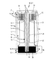
図1の温度センサ10は、(詳しく図示しなかった)ホットランナーシステム、特に(図示しなかった)ホットランナーシステム用の加熱装置40の構成部品である。この温度センサ10は、温度が上昇又は降下するときにその電気抵抗が変化する材料から作られた抵抗素子20を有する。この抵抗素子20は、(図示しなかった)適切な電子制御回路によって加熱装置40によって生成された温度の記録と適切な制御に対する基礎を提供する。
1 is a component part of a
抵抗素子20は、ほぼ縦方向にホットランナーノズル又は加熱システム40内に延在している。この抵抗素子20は、3つのセグメント22,24,22に分割されている。これらの3つのセグメント22,24,22は一緒に、比較的狭いU字状のループを形成する。これらのセグメント22は、2つの同一の抵抗脚部を形成する。これらの抵抗脚部は、ホットランナーノズルの本体Kに対して平行にほぼ延在している。これらの抵抗脚部は、サブセグメント24を介してこれらの抵抗脚部の下端部で連結されている。このサブセグメント24の電気抵抗は、特定の温度でセグメント22の電気抵抗の2〜100倍である。このことは、例えばサブセグメント24の断面積の少なくとも2倍の断面積を有する各セグメント22によって実現され得る。しかしながら、好ましい配置では、セグメント22とサブセグメント24が均一な厚さのU字状の抵抗経路を形成する。図2中に示したように、セグメント22の領域の幅は、サブセグメント24の領域よりも大きい。温度センサ10又は抵抗素子20の温度センサ10の長さLは、ホットランナーノズルの本体Kの長さにほぼ等しい。
The
連結接触部30が、温度センサ10を電子評価制御回路に接続するために設けられている。これらの連結接触部30は、例えば半田付けしてもよい。接続ワイヤ又はケーブルが、これらの半田付け接触部30に付加されている。これらの半田付け接触部30は、ノズル本体又は連結フランジから突出している。
A connecting
加熱装置40は、好ましくは加熱素子42を有する。これらの加熱素子42は、電気的な熱伝導経路44である。蛇行リボン52に対する連結部50は、上端領域O、例えばベース又は(図示しなかった)ホットランナーノズルの前に位置決めされている。リボンの平行な熱伝導経路は、個々の伝導経路の幅に等しい距離で互いに分離されている。上のリボン52は、接合部53で変化してフレーム状の枝部又は長手方向リード54を形成する。この長手方向リード54は、加熱装置40又はノズル本体Kの中間領域Bを通過する。これらの長手方向リード又は枝部54は、それらの下端部55に集合し、端部領域又はノズル本体Kのチップ領域Eの下の蛇行リボン56、特に(図示しなかった)ノズルチップの領域内に至る。上の蛇行リボン52、枝部の領域及び長手方向リード54内の熱伝導経路44の幅は、下の蛇行リボン56内の熱伝導経路44の幅よりも大きい。その結果、下の蛇行リボン56の電気抵抗は、熱伝導経路44以外の熱伝導経路の電気抵抗よりも大きい。したがって、熱性能は、ノズルチップの領域E内に集中される。
The
熱伝導体42,44の対称な配置が図1の特徴である。これらの熱伝導体の片方が、中央に位置決めされた温度センサ10を二分割する。この温度センサ10は、サブセンサ24と共にヘアピン状のループを形成する。このヘアピン状のループは、特に敏感な測定領域を構成する。このサブセグメントは、下の蛇行リボン56の近くに構成された熱伝導経路44によって高抵抗の熱伝導領域46の凹部47内に包囲されていて、ホットランナーのノズルチップの領域E内に位置決めされている。この場合、この領域内の温度のどんなばらつきも、抵抗素子20に対して大いに影響する。
The symmetrical arrangement of the
加熱装置40の熱伝導経路42,22は、例えば0.02と0.5mm との間の均一な厚さの平坦なストリップである。これらの熱伝導経路42,44は、好ましくは伝導性の薄膜又は絶縁層52上に焼結されたペーストから構成される。この絶縁層52は、マニホルド又はノズルの本体Kに前もって接着してある。この絶縁層は、好ましくはセラミックの誘電体層である。この誘電体層は、少なくとも1回の焼結後にマニホルド又はノズルの補運体Kに対して予備押圧される。温度センサ10の抵抗素子20は、好ましくは熱伝導経路42,44と同じ高さで誘電体層58に厚膜技術によって固定されている。温度センサ10は、温度の変化と共にその抵抗が変化する白金又は別の適切な金属の合金でもよい。さらなる絶縁層59は、加熱システム40と温度センサ10を外部の影響から保護する。これらの絶縁層58,59は、ホットランナーノズルの平坦な側面又はシリンダ状のジャケット面に対して適用される共通の保護化合物から成る。
The
ホットランナーノズルの端部領域又はチップ領域E(温度変化を感知する領域)内の抵抗素子20の独立したサブセグメント24のこの形と位置が、そこでの熱の消失の正確で迅速な記録を可能にする。したがって、定格温度からずれると、本発明の温度センサ10内の抵抗が、従来の温度センサのときよりもかなり速くかつ顕著に変化する。すなわち、定格温度からのずれが、迅速にかつ正確に記録でき、加熱システム40の迅速な制御を可能にする。
This shape and position of the
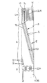
図3は、図2の温度センサ10の断面図である。加熱システム40は、ノズル本体Kの外壁上に位置決めされている。この加熱システム40は、絶縁層として金属に直接被覆されたセラミックの誘電体層58を伴った平坦な層の加熱システムとして形成されている。その結果、加熱層42が、金属に対して被覆されていて、(図1中に示したように)蛇行及び/又はフレーム状の熱伝導経路44と外層59を構成する。この外層59は、熱伝導経路44とこの熱伝導経路44の下の誘電体層58を覆い、外部に対して遮蔽して電気的に絶縁する。さらなる絶縁層26が、外層59に対して被覆されている。温度センサ10が、この外層59中に埋設されている。
FIG. 3 is a cross-sectional view of the
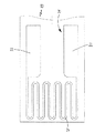
図4中に示された形態では、温度センサのサブセグメント24が蛇行の形である。ここでも、このサブセグメント24は、ホットランナーノズル上の領域内に位置決めされて特に敏感な測定領域を構成する。ここでは、この領域の温度ができる限り迅速に記録される。図5,6は各々、熱伝導経路44及び温度センサ10の配置と位置の別のオプションを示す。温度センサ10の測定チップ24が、所望の温度測定領域内に常に存在する。
In the form shown in FIG. 4, the sub-segment 24 of the temperature sensor has a meandering shape. Again, this sub-segment 24 is positioned in a region on the hot runner nozzle and constitutes a particularly sensitive measurement region. Here, the temperature of this region is recorded as quickly as possible. 5 and 6 each show another option for placement and location of the heat transfer path 44 and
本発明は、上述した形態に限定されず、いろいろに変更できる。例えば、温度センサ10のセグメント22とサブセグメント24が、上下に重なって配置された2つの抵抗経路20によって形成され、かつ薄い絶縁層によって分離されてもよい。このことは、より高い抵抗値を可能にする。これらのより高い抵抗値は、例えばより高い温度を測定するために要求される。ここでも、温度のばらつきが抵抗経路20のその他の領域よりも迅速にかつ正確に記録されなければならない領域内では、抵抗素子20の抵抗値が遙かに大きいこと、すなわち2〜100 倍の割合で大きいことが重要である。その結果、熱センサ10は、最少の熱遅延で選択された領域内の温度変化を検出する。
The present invention is not limited to the above-described form and can be variously changed. For example, the
有益な発展型では、伝導性のマニホルド又はノズル本体に絶縁的に取り付けるのに適する装置の全体が均一な厚さである。このことは、厚膜を簡単にかつ確実に埋設させる。厚膜は、それ自体公知の方法を使用して焼結され得る。ガラスセラミックシステムは、少なくとも1つのガラス、ガラスセラミック又はセラミック化合物を既に含有する。このガラス、ガラスセラミック又はセラミック化合物は、それぞれの焼結温度で金属の表面を湿潤させ、少なくともその一部を結晶状態に遷移させる。 In an advantageous development, the entire device suitable for insulative mounting on a conductive manifold or nozzle body is of uniform thickness. This allows the thick film to be embedded easily and reliably. The thick film can be sintered using methods known per se. Glass ceramic systems already contain at least one glass, glass ceramic or ceramic compound. This glass, glass ceramic or ceramic compound wets the surface of the metal at the respective sintering temperatures, and at least part of it transitions to the crystalline state.
特許請求の範囲中に記されている全ての特徴、利点、説明、図面、構成の詳細及び空間的配置は、個別に又は多様な組み合わせにおける本発明に対して必須要件である。 All features, advantages, descriptions, drawings, configuration details and spatial arrangements recited in the claims are essential to the invention either individually or in various combinations.
B 中間領域
E 終端領域/チップ領域
K マニホルド/ノズル本体
L 長さ
O 上端領域
10 温度センサ
20 抵抗素子
22 セグメント
24 サブセグメント
26 絶縁層
30 連結接触部
40 加熱システム/加熱装置
42 加熱素子
44 熱伝導経路
46 帯域
47 凹部
50 連結部
52 蛇行リボン
53 接合部
54 長手方向リード
55 集中部
56 蛇行リボン
58 絶縁層
59 絶縁層
B Intermediate region E Termination region / Chip region K Manifold / Nozzle body L Length O
Claims (24)
Applications Claiming Priority (1)
| Application Number | Priority Date | Filing Date | Title |
|---|---|---|---|
| DE20211328U DE20211328U1 (en) | 2002-07-26 | 2002-07-26 | Temperature sensor and heating device for hot runner systems |
Publications (2)
| Publication Number | Publication Date |
|---|---|
| JP2004130782A true JP2004130782A (en) | 2004-04-30 |
| JP2004130782A5 JP2004130782A5 (en) | 2005-09-08 |
Family
ID=7973433
Family Applications (1)
| Application Number | Title | Priority Date | Filing Date |
|---|---|---|---|
| JP2003280198A Pending JP2004130782A (en) | 2002-07-26 | 2003-07-25 | Temperature sensor and heating apparatus for use in hot runner system |
Country Status (14)
| Country | Link |
|---|---|
| US (1) | US6897418B1 (en) |
| EP (1) | EP1384561B1 (en) |
| JP (1) | JP2004130782A (en) |
| KR (1) | KR20040010380A (en) |
| CN (1) | CN100360295C (en) |
| AT (1) | ATE324243T1 (en) |
| CA (1) | CA2436171A1 (en) |
| DE (2) | DE20211328U1 (en) |
| DK (1) | DK1384561T3 (en) |
| ES (1) | ES2262926T3 (en) |
| HK (1) | HK1061997A1 (en) |
| PT (1) | PT1384561E (en) |
| SI (1) | SI1384561T1 (en) |
| TW (1) | TWI231258B (en) |
Families Citing this family (15)
| Publication number | Priority date | Publication date | Assignee | Title |
|---|---|---|---|---|
| ES2217989B1 (en) * | 2004-06-04 | 2005-12-16 | Fagor, S.Coop. | NATURAL CONVECTION ELECTRIC HEATING DEVICE. |
| US8536496B2 (en) * | 2004-09-15 | 2013-09-17 | Watlow Electric Manufacturing Company | Adaptable layered heater system |
| EP1803328B1 (en) * | 2004-09-30 | 2012-04-11 | Watlow Electric Manufacturing Company | Modular layered heater system |
| DE102006049667A1 (en) | 2006-10-18 | 2008-04-24 | Günther Heisskanaltechnik Gmbh | Electric heating device for hot runner systems |
| DE202007001789U1 (en) * | 2007-02-02 | 2008-06-12 | Günther Heisskanaltechnik Gmbh | injection molding |
| DE202007011746U1 (en) | 2007-08-22 | 2007-10-31 | Günther Heisskanaltechnik Gmbh | Electric heating for heating substantially cylindrical objects |
| EP2046102B1 (en) * | 2007-10-01 | 2009-12-30 | Siemens Aktiengesellschaft | Assembly with a module and a module rack |
| DE202008013626U1 (en) * | 2008-10-15 | 2009-02-19 | Türk & Hillinger GmbH | Tubular heating element with temperature sensor |
| DE102010033153B4 (en) | 2010-08-03 | 2020-06-18 | Otto Männer Innovation GmbH | Injection molding nozzle |
| CN102378414B (en) * | 2010-08-06 | 2013-06-12 | 友丽系统制造股份有限公司 | Micro-heater with temperature monitoring function |
| DE102010055934B4 (en) * | 2010-12-23 | 2018-09-06 | Epcos Ag | Actuator and method for its production |
| DE102014005284B4 (en) | 2013-04-09 | 2022-10-20 | Otto Männer Innovation GmbH | Heater-thermocouple assembly and assembly with a heater-thermocouple assembly and a sleeve |
| EP3096585B1 (en) * | 2015-05-18 | 2017-12-20 | E.G.O. ELEKTRO-GERÄTEBAU GmbH | Heating device for heating fluids and a method for operating such a heating device |
| CN107678461B (en) * | 2017-11-16 | 2023-05-16 | 保定天威线材制造有限公司 | Automatic paint adding temperature control device and method |
| TWI845400B (en) * | 2023-08-18 | 2024-06-11 | 豐泰企業股份有限公司 | Apparatus for manufacturing shoe material with real-time temperature measuring system and method for manufacturing shoe material |
Family Cites Families (17)
| Publication number | Priority date | Publication date | Assignee | Title |
|---|---|---|---|---|
| GB1248298A (en) | 1969-03-07 | 1971-09-29 | John Macmanus | Packaged cake |
| DE3924518A1 (en) * | 1989-07-25 | 1991-01-31 | Haefele Umweltverfahrenstechik | TEMPERATURE SENSOR AND METHOD FOR THE PRODUCTION THEREOF |
| DE4025715C1 (en) * | 1990-08-14 | 1992-04-02 | Robert Bosch Gmbh, 7000 Stuttgart, De | |
| JPH06507521A (en) * | 1991-02-15 | 1994-08-25 | シーメンス アクチエンゲゼルシヤフト | Device for high speed platinum group metal temperature sensor for high temperature sensor technology |
| JP2968111B2 (en) * | 1991-11-22 | 1999-10-25 | 日本特殊陶業株式会社 | Resistor physical quantity sensor with migration prevention pattern |
| US5436494A (en) * | 1994-01-12 | 1995-07-25 | Texas Instruments Incorporated | Temperature sensor calibration wafer structure and method of fabrication |
| US6022210A (en) * | 1995-01-31 | 2000-02-08 | Gunther Heisskanaltechnik Gmbh | Hot runner nozzle |
| US6140906A (en) * | 1996-11-08 | 2000-10-31 | Tdk Corporation | Resistive temperature sensor and manufacturing method therefor |
| JP3571494B2 (en) * | 1997-05-20 | 2004-09-29 | 日本碍子株式会社 | Gas sensor |
| EP0927617B1 (en) | 1997-12-19 | 2001-06-06 | Günther GmbH & Co.KG Metallverarbeitung | Hot runner nozzle |
| US5973296A (en) * | 1998-10-20 | 1999-10-26 | Watlow Electric Manufacturing Company | Thick film heater for injection mold runner nozzle |
| DE19934109C1 (en) * | 1999-07-21 | 2001-04-05 | Bosch Gmbh Robert | Temperature sensor and process for its manufacture |
| DE19934110C2 (en) * | 1999-07-21 | 2001-07-12 | Bosch Gmbh Robert | Temperature sensor |
| DE19941038A1 (en) * | 1999-08-28 | 2001-03-01 | Guenther Heiskanaltechnik Gmbh | Electric heater for hot runner systems and method for producing such a heater |
| EP1254004B1 (en) * | 2000-01-31 | 2004-08-18 | Günther Heisskanaltechnik GmbH | Nozzle for injection moulding tool and nozzle arrangement |
| DE10004072C2 (en) | 2000-01-31 | 2002-07-25 | Guenther Heiskanaltechnik Gmbh | Nozzle for injection molds and nozzle arrangement |
| DE10045940B4 (en) * | 2000-09-16 | 2017-08-03 | Robert Bosch Gmbh | temperature sensor |
-
2002
- 2002-07-26 DE DE20211328U patent/DE20211328U1/en not_active Expired - Lifetime
-
2003
- 2003-07-09 TW TW092118689A patent/TWI231258B/en not_active IP Right Cessation
- 2003-07-11 ES ES03015840T patent/ES2262926T3/en not_active Expired - Lifetime
- 2003-07-11 DE DE50303085T patent/DE50303085D1/en not_active Expired - Fee Related
- 2003-07-11 DK DK03015840T patent/DK1384561T3/en active
- 2003-07-11 SI SI200330368T patent/SI1384561T1/en unknown
- 2003-07-11 PT PT03015840T patent/PT1384561E/en unknown
- 2003-07-11 AT AT03015840T patent/ATE324243T1/en not_active IP Right Cessation
- 2003-07-11 EP EP03015840A patent/EP1384561B1/en not_active Expired - Lifetime
- 2003-07-15 US US10/618,662 patent/US6897418B1/en not_active Expired - Fee Related
- 2003-07-25 CA CA002436171A patent/CA2436171A1/en not_active Abandoned
- 2003-07-25 CN CNB031331998A patent/CN100360295C/en not_active Expired - Fee Related
- 2003-07-25 JP JP2003280198A patent/JP2004130782A/en active Pending
- 2003-07-25 KR KR1020030051234A patent/KR20040010380A/en not_active Application Discontinuation
-
2004
- 2004-07-12 HK HK04105058A patent/HK1061997A1/en not_active IP Right Cessation
Also Published As
| Publication number | Publication date |
|---|---|
| US6897418B1 (en) | 2005-05-24 |
| DE50303085D1 (en) | 2006-06-01 |
| TW200405853A (en) | 2004-04-16 |
| DK1384561T3 (en) | 2006-08-14 |
| KR20040010380A (en) | 2004-01-31 |
| EP1384561B1 (en) | 2006-04-26 |
| ES2262926T3 (en) | 2006-12-01 |
| HK1061997A1 (en) | 2004-10-15 |
| CN1478644A (en) | 2004-03-03 |
| PT1384561E (en) | 2006-09-29 |
| CN100360295C (en) | 2008-01-09 |
| ATE324243T1 (en) | 2006-05-15 |
| EP1384561A1 (en) | 2004-01-28 |
| CA2436171A1 (en) | 2004-01-26 |
| SI1384561T1 (en) | 2006-10-31 |
| TWI231258B (en) | 2005-04-21 |
| DE20211328U1 (en) | 2002-10-17 |
Similar Documents
| Publication | Publication Date | Title |
|---|---|---|
| JP2004130782A (en) | Temperature sensor and heating apparatus for use in hot runner system | |
| US7106167B2 (en) | Stable high temperature sensor system with tungsten on AlN | |
| CN106465481B (en) | Planar heating element with PTC resistor structure | |
| EP1499860A1 (en) | Mass flow meter with chip-type sensors | |
| CN112042265B (en) | Resistive heater with temperature sensing power pin and auxiliary sensing tab | |
| US5057811A (en) | Electrothermal sensor | |
| JPH05133780A (en) | Flow rata sensor | |
| JP2004529457A (en) | Electric heating element | |
| US9810586B2 (en) | Temperature sensor and thermal, flow measuring device | |
| JPH0495820A (en) | Thermal mass flowmeter | |
| JPH0868699A (en) | Thermister sensor | |
| KR940001270Y1 (en) | Heat block of wire bonder | |
| JP2004219123A (en) | Temperature measuring probe | |
| US6250150B1 (en) | Sensor employing heating element with low density at the center and high density at the end thereof | |
| JP4230799B2 (en) | Average temperature measurement sensor and dummy wafer and temperature control device using the same | |
| JPH0868698A (en) | Thermister sensor | |
| US5361634A (en) | Heat-sensitive flow rate sensor | |
| JP2001153707A (en) | Flow sensor | |
| WO2024062521A1 (en) | Temperature sensor, and rotary electrical machine | |
| KR100403140B1 (en) | heat block device for manufacturing semiconductor package | |
| KR20000059127A (en) | Fabrication method of thermocouple wafer and temperature measurement method by using thermocouple wafer | |
| CN207280625U (en) | A kind of electronic cigarette temperature sensor | |
| JP3740027B2 (en) | Flow sensor | |
| JPH0146010B2 (en) | ||
| JPH05142008A (en) | Sensor device |
Legal Events
| Date | Code | Title | Description |
|---|---|---|---|
| A521 | Request for written amendment filed |
Free format text: JAPANESE INTERMEDIATE CODE: A523 Effective date: 20050517 |
|
| A621 | Written request for application examination |
Free format text: JAPANESE INTERMEDIATE CODE: A621 Effective date: 20050517 |
|
| A977 | Report on retrieval |
Free format text: JAPANESE INTERMEDIATE CODE: A971007 Effective date: 20080125 |
|
| A131 | Notification of reasons for refusal |
Free format text: JAPANESE INTERMEDIATE CODE: A131 Effective date: 20080219 |
|
| A601 | Written request for extension of time |
Free format text: JAPANESE INTERMEDIATE CODE: A601 Effective date: 20080515 |
|
| A602 | Written permission of extension of time |
Free format text: JAPANESE INTERMEDIATE CODE: A602 Effective date: 20080520 |
|
| A601 | Written request for extension of time |
Free format text: JAPANESE INTERMEDIATE CODE: A601 Effective date: 20080618 |
|
| A602 | Written permission of extension of time |
Free format text: JAPANESE INTERMEDIATE CODE: A602 Effective date: 20080623 |
|
| A601 | Written request for extension of time |
Free format text: JAPANESE INTERMEDIATE CODE: A601 Effective date: 20080718 |
|
| A602 | Written permission of extension of time |
Free format text: JAPANESE INTERMEDIATE CODE: A602 Effective date: 20080724 |
|
| A521 | Request for written amendment filed |
Free format text: JAPANESE INTERMEDIATE CODE: A523 Effective date: 20080818 |
|
| A131 | Notification of reasons for refusal |
Free format text: JAPANESE INTERMEDIATE CODE: A131 Effective date: 20090721 |
|
| A02 | Decision of refusal |
Free format text: JAPANESE INTERMEDIATE CODE: A02 Effective date: 20100112 |