KR930002544B1 - Matrix coating flexible casting belts, method and apparatus for making matrix coatings - Google Patents
Matrix coating flexible casting belts, method and apparatus for making matrix coatings Download PDFInfo
- Publication number
- KR930002544B1 KR930002544B1 KR1019840006977A KR840006977A KR930002544B1 KR 930002544 B1 KR930002544 B1 KR 930002544B1 KR 1019840006977 A KR1019840006977 A KR 1019840006977A KR 840006977 A KR840006977 A KR 840006977A KR 930002544 B1 KR930002544 B1 KR 930002544B1
- Authority
- KR
- South Korea
- Prior art keywords
- belt
- metal
- coating
- zirconia
- casting
- Prior art date
Links
Images


Classifications
-
- B—PERFORMING OPERATIONS; TRANSPORTING
- B22—CASTING; POWDER METALLURGY
- B22D—CASTING OF METALS; CASTING OF OTHER SUBSTANCES BY THE SAME PROCESSES OR DEVICES
- B22D11/00—Continuous casting of metals, i.e. casting in indefinite lengths
- B22D11/06—Continuous casting of metals, i.e. casting in indefinite lengths into moulds with travelling walls, e.g. with rolls, plates, belts, caterpillars
-
- B—PERFORMING OPERATIONS; TRANSPORTING
- B05—SPRAYING OR ATOMISING IN GENERAL; APPLYING FLUENT MATERIALS TO SURFACES, IN GENERAL
- B05B—SPRAYING APPARATUS; ATOMISING APPARATUS; NOZZLES
- B05B13/00—Machines or plants for applying liquids or other fluent materials to surfaces of objects or other work by spraying, not covered by groups B05B1/00 - B05B11/00
- B05B13/02—Means for supporting work; Arrangement or mounting of spray heads; Adaptation or arrangement of means for feeding work
- B05B13/04—Means for supporting work; Arrangement or mounting of spray heads; Adaptation or arrangement of means for feeding work the spray heads being moved during spraying operation
- B05B13/0463—Installation or apparatus for applying liquid or other fluent material to moving work of indefinite length
- B05B13/0468—Installation or apparatus for applying liquid or other fluent material to moving work of indefinite length with reciprocating or oscillating spray heads
- B05B13/0473—Installation or apparatus for applying liquid or other fluent material to moving work of indefinite length with reciprocating or oscillating spray heads with spray heads reciprocating along a straight line
-
- B—PERFORMING OPERATIONS; TRANSPORTING
- B22—CASTING; POWDER METALLURGY
- B22D—CASTING OF METALS; CASTING OF OTHER SUBSTANCES BY THE SAME PROCESSES OR DEVICES
- B22D11/00—Continuous casting of metals, i.e. casting in indefinite lengths
- B22D11/06—Continuous casting of metals, i.e. casting in indefinite lengths into moulds with travelling walls, e.g. with rolls, plates, belts, caterpillars
- B22D11/0637—Accessories therefor
- B22D11/0665—Accessories therefor for treating the casting surfaces, e.g. calibrating, cleaning, dressing, preheating
- B22D11/0671—Accessories therefor for treating the casting surfaces, e.g. calibrating, cleaning, dressing, preheating for heating or drying
Abstract
내용 없음.No content.
Description
제1도는 트윈벨트 연속주조기의 주조영역, 주조벨트와 풀리 및 주조측방댐중 하나를 도시하는 측면도.1 is a side view showing one of a casting zone, a casting belt and a pulley and a casting side dam of a twin belt continuous casting machine;
제2도는 제1도의 2-2선을 따라 취해진 주조공간과 그 주변부의 확대단면도.2 is an enlarged cross-sectional view of the casting space and its periphery taken along line 2-2 of FIG.
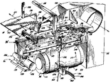
제3도는 공전끝단(idling end)으로부터 본 단독벨트 피복기의 사시도.3 is a perspective view of a single belt covering machine viewed from an idling end.
제4도는 제3도의 4-4선을 따라 취한 제3도의 단독벨트 피복기의 조향기구(steering mechanism)의 확대사시도.4 is an enlarged perspective view of the steering mechanism of the single belt coater of FIG. 3 taken along line 4-4 of FIG.
제5도는 제3도의 피복기의 변형예의 사시도.5 is a perspective view of a modification of the coating machine of FIG.
제6도는 벨트피복기의 작업단부에서 본 바람직한 측방 "부동"열용사 총 집합체의 확대사시도이며, 제3도와 제5도에 나타낸 벨트피복기의 개량형을 도시한 것.FIG. 6 is an enlarged perspective view of the preferred lateral "floating" thermal spray gun assembly seen from the working end of the belt covering machine, showing an improved version of the belt covering machine shown in FIGS.
본 발명은 첫째 철 또는 비철금속을 주조하기 위한 연속주조기에 사용되는 가요성 벨트에 관한 것이다. 보다 구체적으로, 본 발명은 보호적이고 열적으로 절연인 매트릭스 피복, 피복형성방법, 피복의 조성, 및 그렇게 제조된 피복된 벨트를 지향하고 있다. 주조벨트는 보통 연강(mild steel)으로 제작된다. 둘째 본 발명은 측방댐 블럭의 피복과 같은 연속주조기내의 다른 용융금속 접촉면의 피복에도 적용된다.The present invention first relates to a flexible belt for use in a continuous casting machine for casting ferrous or nonferrous metals. More specifically, the present invention is directed to protective and thermally insulated matrix coatings, coating formation methods, coating compositions, and coated belts so produced. Casting belts are usually made of mild steel. Secondly, the present invention also applies to the coating of other molten metal contact surfaces in continuous casting machines, such as the coating of side dam blocks.
기름, 그라파이트, 수트(soot), 규조트, 실리카, 유기결합제등의 여러 혼합물이 금속주조벨트를 보호하거나 또는 금속주조벨트를 절연하고/또는 용융금속주조용 연속주조기의 벨트에 접착하는 것을 방지하는 분리제로서 작용하였다. 이런 종래의 피복은 본질적으로 임시적이거나 일시적이였고 주조공정동안에 계속 제공되거나 보충되어야 했다. 주조공정동안의 그런 피복을 계속 제공하는 것은 계속된 열전도성이 필요하다는견지에서 정확히 유지되고 제어되는 것이 필요하다.Various mixtures of oils, graphite, soot, diatoms, silica, organic binders, etc. protect the metal casting belts or insulate the metal casting belts and / or prevent them from adhering to the belt of continuous casting machines for molten metal castings. It acted as a separating agent. These conventional sheaths were inherently temporary or temporary and had to be continuously provided or supplemented during the casting process. Providing such coatings during the casting process needs to be accurately maintained and controlled in the sense that continued thermal conductivity is required.
임시적인 절연피복을 연속적으로 피복하는 것과 보충하는 것은 어렵고 부정확한 기술이다. 예컨대, 과도한 용액 또는 용매 결합제가 절연피복 물질내에 있으면, 주조물의 견고성을 파괴할만큼의 가스를 발생시켜 결국 기공을 만든다. 그렇게 유리된 가스는 종종 수소이고 이것은 주조금속의 야금학적 특성을 나쁘게 변경시킬 수 있다. 또 과잉량의 일시적 절연피복 물질자체가 주조품의 가장자리 근방에 축적되고 연속적으로 이동하는 주형공간의 일부를 침해하여 주조품에 결함을 야기시키는 경우가 있다.Continuous coating and replacement of temporary insulating coatings is a difficult and inaccurate technique. For example, if excess solution or solvent binder is in the insulating coating material, it generates enough gas to destroy the firmness of the casting and eventually create pores. The gas so liberated is often hydrogen and this can adversely alter the metallurgical properties of the cast metal. In addition, an excessive amount of temporary insulating coating material itself may accumulate near the edges of the casting and intrude some of the continuously moving mold space, causing defects in the casting.
알루미늄, 아연 및 납과 같은 비교적 저융점 금속을 연속주조하는데 사용되며 열경화성수지와 용매를 함유하는 2층 벨트피복은 미합중국 특허 제3,871,905호에 개시되어 있다. 수지를 함유하는 피복은 일반적으로 알루미늄보다 융점이 훨씬 높은 금속을 연속주조하는데는 적합치 못하다.Two-layer belt coatings used for continuous casting of relatively low melting metals such as aluminum, zinc and lead and containing thermosetting resins and solvents are disclosed in US Pat. No. 3,871,905. Resin-containing coatings are generally not suitable for continuous casting of metals with much higher melting points than aluminum.
0.2 내지 0.8중량%의 티타늄을 함유하는 연킬드강으로 제조된 주조벨트는 미합중국 특허 제4,298,053호에 설명된 것처럼 다층피복되어 있다. 벨트표면은 우선 니켈-알루미늄합금(80중량%의 Ni과 20중량% Al)인 "프라이머"층으로 피복되는데 명세서에는 두께가 0.005mm인것으로 기술되어 있으나 청구범위에서만은 두께가 0.05mm인 것으로 청구되었다.Casting belts made of soft-kilted steel containing 0.2 to 0.8 weight percent titanium are multi-layered as described in US Pat. No. 4,298,053. The belt surface is first covered with a "primer" layer of nickel-aluminum alloy (80% by weight Ni and 20% by weight Al), which is described as 0.005 mm thick but claims only 0.05 mm thick. It became.
프라이머층은 크롬, 크롬합금, 니켈, 니켈합금, 또는 스테인레스강으로 되어 있는 두께 0.01 내지 0.5mm인 다른층으로 피복된다.The primer layer is coated with chromium, chromium alloys, nickel, nickel alloys, or other layers of 0.01 to 0.5 mm in thickness made of stainless steel.
다음에, 클로이드형 그라파이트 반 접착제(anti-adhension agent)인 제3층이 둘째층위에 다시 제공된다.Next, a third layer, which is a closed graphite anti-adhension agent, is provided again on the second layer.
그러나, 본 원인의 경험에 의하면, 하기한 것과 같은 상기 특허에 따라 획득될 수 있는 것보다 더 큰 열적절연과 부가적인 비습윤성이 요구된다.However, experience of the present cause requires greater thermal insulation and additional non-wetting than can be obtained according to the above patents as described below.
심과 곤교스의 캐나다 특허 제1,062,877호는 필수적인 내열성을 제공하기 위하여 세라믹층이 원하는 두께가 될때까지 무단 주조벨트상에 여러겹의 얇은 층(80-100μm, 바람직하게는 50-70μm)으로 무단주조벨트를 피복하는 것에 대하여 기술하고 있다.Shim and Gonzago's Canadian Patent No. 1,062,877 is an endless casting of multiple layers (80-100 μm, preferably 50-70 μm) on an endless cast belt until the ceramic layer has the desired thickness to provide the necessary heat resistance. The coating of the belt is described.
다중 세라믹층을 형성하는 것은 수고스럽고 시간소비적이며 경비가 비싸다.Forming multiple ceramic layers is laborious, time consuming and expensive.
이렇게 해서 얻은 적층피복(built-up coating)은 다층 세라믹피복과 주조되는 알루미늄 사이의 습윤거동과 균일한 표면마무리를 위하여 그라인딩과 같은 기계가공이 시행된다. 적층세라믹 피복은 A12O3ㆍCaZrO3, A12O3ㆍMgO, ZrSiO4또는 A12O3ㆍTiO2로 구성된다.The built-up coating thus obtained is subjected to machining, such as grinding, for the wetting behavior and uniform surface finish between the multilayer ceramic coating and the cast aluminum. The laminated ceramic coating is composed of A1 2 O 3 .CaZrO 3 , A1 2 O 3 .MgO, ZrSiO 4 or A1 2 O 3 .TiO 2 .
10-4내지 10-3m2ㆍhㆍC/kca1 범위의 내열성을 제공할때까지 두께를 입힌다. 적층피복은 통상 비교적 두께가 두껍고 취약하다. 열충격, 기계적 신장과 이완, 및 유연성과 마모성에 견딜 수 있는 내구성이 부족한데, 이런것은 용융금속접촉 냉각표면으로써 1이상의 이동벨트를 채택하는 연속주조기의 공통된 특성이다.The thickness is applied until it provides heat resistance in the range of 10 −4 to 10 −3 m 2 · h · C / kca 1. Laminated coatings are usually relatively thick and fragile. Lack of durability to withstand thermal shock, mechanical elongation and relaxation, and flexibility and wear, a common feature of continuous casting machines employing one or more moving belts as molten metal contact cooling surfaces.
그러한 기계적, 열적응력에 견디는 내구성은 중요한데 내구성이 없으면 세라믹피복의 조각들은 용융금속의 연속주조에 필요한 작업을 하는 동안 떨어져서 벗겨진다.Durability to withstand such mechanical and thermal stresses is important, without which the pieces of ceramic coating are peeled off during the work required for continuous casting of molten metal.
떨어진 조각은 주조금속 제품에 들어가는 것을 피할 수 없다.Falling pieces are inevitable to get into cast metal products.
그러한 혼입은 예컨대 미세한 와이어로 인발가공될 구리의 경우에 심각한 문제가 될 수 있다. 이런 혼입은 다이에서 와이어가 끊어져서 와이어를 다시 연결해야 하는 것 같은 생산성 감소를 초래한다.Such incorporation can be a serious problem, for example in the case of copper to be drawn into fine wires. This mixing leads to a decrease in productivity, such as breaking the wire at the die and requiring the wire to be reconnected.
세라믹 피복은 통상 가요성이 없어서 잘 부서지는 경향이 있다.Ceramic coatings are usually inflexible and tend to break.
부스러짐, 박리 및 세라믹 입자에 의한 주조품의 오염에 관련된 제반문제가 데오발드의 독일 특허 2411448호에 강조되어 있으며, 알루미늄주조시에 주조될 금속보다 융점이 더 높은 제2의 보호적인 내마모성 금속층을 비교적 두꺼운 세라믹위에 제공함으로써 이런 문제를 해결하고자 시도한 사항이 상기 특허에 기술되어 있다.The problems associated with chipping, delamination and contamination of castings with ceramic particles are highlighted in Deobald's German Patent No. 2411448, which provides a second protective wear resistant metal layer with a higher melting point than the metal to be cast during aluminum casting. Attempts to solve this problem by providing on relatively thick ceramics are described in this patent.
연속주조기용 무단 가요성 금속주조벨트상의 단층인 부분적으로 금속성이며, 적당한 밀착성, 기계적ㆍ열적 내구성과 비습윤성이 있는 용착매트릭스 피복을 기술하고 있다.Partially metallic, single layer on endless flexible metal casting belts for continuous casting machines, the deposition matrix coating having adequate adhesion, mechanical and thermal durability and non-wetting.
또한 이 용착매트릭스 피복은 연속주조기의 다른 용융금속 접촉표면 예컨대, 주형공동부의 이동측벽을 획정하는 측방댐 블럭을 피복하는데 유용하다.The deposition matrix coating is also useful for covering other molten metal contact surfaces of the continuous casting machine, for example, side dam blocks that define the moving side walls of the mold cavity.
용착매트릭스(또는 망상조직) 피복은 피복전반에 걸쳐 유용한 액세시블기공(accessible porosity)을 제공하고 내열금속 또는 금속합금 예를들어, 니켈 또는 니켈합금의 매트릭스에 실질적으로 균일하게 산재되어있는 비금속 내화재로 구성되며 이런 금속 또는 금속합금은 벨트의 그릿-블라스트(grit-blast)된 표면에 용착되어 비금속물질을 고착하고 지지한다.The deposition matrix (or reticulated) coating provides a useful accessible porosity throughout the coating and is a nonmetal refractory material that is substantially uniformly interspersed in a matrix of heat-resistant metals or metal alloys, such as nickel or nickel alloys. These metals or metal alloys are deposited on the grit-blasted surface of the belt to adhere and support the nonmetallic material.
피복은 분상혼합물을 거친 표면에 직접 열적으로 용사함으로써 이루어진다.The coating is achieved by thermally thermal spraying the powder mixture directly onto the rough surface.
그 결과된 피복은 용융금속의 직접접촉, 열응력과 결과적인 비틀림 전단변형, 및 용융금속 또는 그 산화물 또는 슬래그에 의한 응력부식거동 또는 화학적부식으로부터 상기 벨트를 절연하고 보호한다.The resulting coating insulates and protects the belt from direct contact of molten metal, thermal stress and resulting torsional shear deformation, and stress corrosion behavior or chemical corrosion by molten metal or its oxides or slags.
비금속물질은 적어도 부분적으로는 금속망상조직에 둘러싸인 고립된 입자형태 및/또는 금속망상조작과 서로 얽힌 제2의 망상조직 형태로 존재한다. 피복된 벨트의 수명은 현저히 증가되며, 주조품의 표면물질과 특성은 상당히 개선된다.The nonmetallic material is at least partly in the form of an isolated particle surrounded by a metal network and / or a second network structure intertwined with the metal network. The life of the coated belt is significantly increased, and the surface material and properties of the cast are significantly improved.
피복은 주조되는 금속의 응고속도를 보다 균일하게 제어하여 결과적으로 야금학적 특성을 개선한다.The coating more uniformly controls the rate of solidification of the metal being cast, resulting in improved metallurgical properties.
열용사에 의한 피복의 구성 및 형성방법을 설명하겠다.The construction and formation method of the coating by thermal spraying will be described.
제1도와 제2도를 보면, 풀리(12와 14) 주위를 도는 하부주조벨트(10)를 포함하는 트윈벨트 주조기의 주조영역과 인접 구성요소를 설명하며 풀리(12와 14)는 하부 캐리지(L)와 결합된 부재이다.1 and 2 illustrate the casting zones and adjacent components of a twin belt casting machine comprising a
풀리(12)는 주조기의 입구 즉 상향단에 위치하며 풀리(14)는 주조기의 출구 즉 하향단에 있다.The pulley 12 is located at the inlet or upstream end of the casting machine and the
연속이동주조주형(C)은 이격되어 있는 한쌍의 측방댐(16과 18)(제2도)과 조합하는 하부주조벨트(10)와 상부주조벨트(20)사이에서 획정되며 상ㆍ하부 주조벨트는 주조영역(C)을 따라 함께 이동한다.The continuous moving casting mold C is defined between the
측방댐은 롤러(22)에 의하여 인도된다. 측방댐은 각각 스트랩(25)이 끼워진 홈이파인 다수의 댐블럭(24)으로 구성되어 있다.Lateral dams are guided by rollers 22. The lateral dams are composed of a plurality of dam blocks 24 each of which are grooves in which the straps 25 are fitted.
시일(seal ; 26)은 벨트사이로 물이 스며드는 것을 방지하여 주조영역(C)으로 물이 스며들지 못하도록 한다.The seal 26 prevents water from penetrating between the belts and prevents water from seeping into the casting zone C.
고정가이드(27)는 이동측방댐을 인도한다. 상부주조벨트(20)는 풀리(28과 30) 주위를 도는데 풀리는 상부캐리지(U)의 부재이다.The
돌기가 달린 백업로울러(finned backup roller)(32)는 주조영역(C)내의 벨트의 위치를 획정하며, 각각의 벨트의 배면을 따라서 냉각수가 신속하게 유동하도록 한다. 제1도의 화살표(31)로 나타낸 것처럼 상향단부에서 주조기내로 용융금속이 공급된다. 주조품(P)은 하향단으로부터 배출된다.A
본 발명에 있어서 각각의 벨트(10과 20)는 각각의 벨트캐리어(L과 U)에 가설되기 전에 피복된다.In the present invention, each of the
제1도와 제2도로부터 알 수 있듯이, 각각의 벨트의 용융금속 접촉표면은 외부면이고 때로는 전방면이라고 부르며 반면에 내부면은 배면이라고 부른다. 가요성 주조벨트(10과 20)는 통상 적당히 경화되도록 압연된 저탄소 강으로 제작되며 그 두께는 0.035 내지 0.065인치인데 더 얇은것이나 두꺼운 것도 사용될 수 있다. 때때로 수요자의 요구에 따라, 톰파스의 미합중국 특허 제4,092,155호에 기술된 바와 같이, 최대경화되도록 충분히 압연하여 가공경화된 티타늄을 함유한 강으로 벨트를 제작할 경우도 있다.As can be seen from Figures 1 and 2, the molten metal contact surface of each belt is the outer surface and sometimes called the front surface, while the inner surface is called the rear surface. The
벨트(10 또는 20)를 피복하기 위해서는 먼저 벨트의 외부면에 잔류하는 기름을 알카리 세척제로 세척한후 청결한 용매로 닦아서 철저히 제거해야 한다.In order to coat the
다음에 벨트의 외부면을 그릿-브라스팅하여 거칠게 한다.The outer surface of the belt is then grit-blasted to roughen it.
예컨대 그릿-브라스팅은 40 내지 100psi(300 내지 700kpa)의 공기압에서 20-그릿의 알루미늄 산화물로 수행한다.Grit-blasting, for example, is performed with 20-grit aluminum oxide at an air pressure of 40-100 psi (300-700 kpa).
20-그릿 크기는 인치당 20줄의 와이어를 갖는 스크린을 통과한 알루미늄 산화물 입자를 말한다.20-grit size refers to aluminum oxide particles that pass through a screen with 20 lines of wire per inch.
상기 공기압 범위중 낮은 범위에 속하는 공기압은 전술한 벨트두께 범위중 얇은 부분에 속하는 보다 얇은 벨트를 그릿 블라스팅할때 사용되며 그렇지 않으면 그릿의 충돌이 벨트의 배면을 거칠게 하기 때문이다.Air pressures belonging to the lower range of the above air pressure ranges are used when grit blasting thinner belts belonging to the thinner part of the aforementioned belt thickness range, because otherwise the impact of the grit roughens the back of the belt.
또한 범위중 낮은 범위에 속하는 공기압은 벨트를 로울러 신장기(roller stretcher)로 평평하게 하지 않을 경우에 권할만하다.Air pressures in the lower range of the range are also recommended when the belt is not flattened by a roller stretcher.
통상 벨트는 하기한 바와 같이 허용한계 범위내로 비틀림 전단변형을 제어하기 위하여 그릿-블라스팅 후에 롤러신장 평판화된다.Typically, the belt is flattened by roller extension after grit-blasting to control the torsional shear deformation within the tolerances as described below.
블라스팅된 표면거칠기는 거칠기의 유용한 범위가 때때로 약 0.001인치에서 0.005인치까지 확장될 수 있더라도 용이하게 얻어지는 범위인 0.002인치에서 0.003인치 사이(2000-3000μinch 또는 52 내지 76μm)인 범위가 바람직하다.The blasted surface roughness is preferably in the range between 0.002 inches and 0.003 inches (2000-3000 μinch or 52-76 μm), which is an easily obtained range, although the useful range of roughness can sometimes extend from about 0.001 inch to 0.005 inch.
전술한 바와 같은 표면거칠기는 바람직한 방법에 의해 표면연마법으로 측정된 값으로 결정한다. 이 바람직한 방법에서, 블라스팅된 벨트시편의 두께는 보통이 마이크로미터 캘리퍼스를 이용하여 측정된다.The surface roughness as described above is determined by the value measured by the surface polishing method by a preferred method. In this preferred method, the thickness of the blasted belt specimen is usually measured using a micrometer caliper.
시편을 표면 연마기의 자기척(magnetic chuck)에 올려놓고 연마된 표면이 매끄러워질때까지 표면을 주의깊게 연마한다.Place the specimen on the magnetic chuck of the surface polisher and carefully polish the surface until the polished surface is smooth.
벨트시편을 다시 마이크로미터 캘리퍼스로 측정하여 측정치의 차이를 거칠기로 여긴다.The belt specimen is again measured with a micrometer caliper to regard the difference in measurements as roughness.
비교해보면, ×400의 현미경으로 수직 측정하여 얻어진 그릿블라스팅된 표면의 최대 거칠기는 본원인의 경험으로 볼때 표면연마와 마이크로미터법에 의하여 얻어진 측정치의 150% 전도이다.In comparison, the maximum roughness of the grit blasted surface obtained by vertical measurement with a microscope of × 400 is, in our experience, 150% conduction of measurements obtained by surface polishing and micrometer methods.
그릿-블라스팅 공정은 보통 벨트를 비틀림 전단변형시킴으로 롤러 신장이 요구된다.Grit-blasting processes usually require roller elongation by torsional shear deformation of the belt.
평판화(leveling)는 예컨대 씨. 더블유. 헤젤렛의 미합중국 특허 2,904,860호에 기술되어 있듯이 벨트의 배면을 다중긴밀롤러를 통하여 통과함으로써 벤딩과 아이롱되어 수행된다.Leveling is for example seed. W. Bending and ironing is performed by passing the back of the belt through a multi-tight roller, as described in Hegelet, US Patent No. 2,904,860.
다음에, 열용사를 사용하여 그릿-블라스팅된 거친 벨트표면에 직접 단면피복인 용착매트릭스 보호ㆍ절연피복을 제공한다.Next, a thermal spray is used to provide a welding matrix protection and insulation coating, which is a single-sided coating, directly on the grit-blasted rough belt surface.
이격처리 : 최소한 5인치(127mm), 트래버스속도(traverse speed) : 분당 30 내지 50피트(9 내지 15미터)로 연소화염(산소아세틸렌화염)에 의하여 피복물질을 열용사하는 것은 훌륭한 방법이다.Spacing: At least 5 inches (127 mm), traverse speed: 30 to 50 feet per minute (9 to 15 meters) is a good way to thermally spray the coating material by combustion flame (oxygen acetylene flame).
용사될 물질이 화염에서 과도하게 연소되지 않는다면 산소아세틸렌 용사피복은 성공적이다.If the material to be sprayed is not overburned in the flame, oxygen acetylene spray coating is successful.
크기가 큰 비금속입자는 완전히 용융되지는 않을 것이다.Large nonmetallic particles will not melt completely.
더욱이, 산소아세틸렌화염은 벨트표면에 침적되는 것과 동일한 종류의 다른 입자들에 비금속입자를 용착하는데 필요한 시간동안 비금속입자를 용융상태로 유지하기에는 충분치 않다.Moreover, the oxygen acetylene salt is not sufficient to keep the nonmetal particles in a molten state for a time necessary for depositing the nonmetal particles on other particles of the same kind as those deposited on the belt surface.
비금속과 혼합된 금속입자가 더 많다면, 이것은 비금속구성요소의 혼합을 위한 좋은 여건이 아니다. 그러므로, 그런 경우에, 적어도 부분적으로 비금속물질은 금속망상조직에 의해 둘러싸인 또는 그 안에 들어있는 고립된 입자형태로 존재할 것이다.If there are more metal particles mixed with the nonmetal, this is not a good condition for mixing the nonmetal components. Thus, in such a case, at least in part the nonmetallic material will be in the form of isolated particles surrounded by or contained within the metal mesh.
프라즈마 용사법은 전기를 사용하는 또다른 열용사법이다.Plasma spraying is another thermal spraying method that uses electricity.
연소(산소아세틸렌)용사는 종종 화염용사(flame spraying)라 불린다. 이런 명명법은 프라즈마용사법이 종종 프라즈마화염을 사용한다고 혼동하기 쉽다. 두 종류의 용사는 모두 화염을 사용한다.Combustion (oxyacetylene) sprays are often called flame spraying. This nomenclature is often confused with the use of plasma flames by the use of plasma flames. Both types of warriors use fire.
"열용사"란 용어는 산소아세틸렌 화염용사와 전기적으로 에너지화된 프라즈마 용사를 포함하는 본원의 용어이다.The term "thermal spray" is a term herein that includes oxygen acetylene flame sprays and electrically energized plasma sprays.
프라즈마 용사는 보통 산소아세틸렌 용사보다 더 높은 고열로 가동되어 결국 기공을 적게 한다.Plasma sprays usually operate at higher temperatures than oxygen acetylene sprays, resulting in less porosity.
전기적으로 에너지화된(프라즈마)용사에 의해 제공된 보다높은 고열은 스틱, 로드 또는 와이어(분상과는 다른)와 같은 조대한 형태로 제공되는 금속과 비금속물질을 보다 신속하게 용융시킬 수 있고 따라서 상기와 같이 조대한 금속과 비금속물질이 채택될 수 있다고 생각한다.The higher high temperatures provided by electrically energized (plasma) sprays can more quickly melt metals and nonmetallic materials provided in coarse form, such as sticks, rods or wires (unlike phases) and thus I think coarse metals and nonmetallic materials can be adopted.
그러나 이것이 실제로 사실인지의 여부에 관계없이, 하기한 바와 같이, 적당한 금속과 비금속구성요소의 혼합물을 사용해서 적절한 율의 액세시블 기공을 가지고 있는 용착매트릭스 피복을 상당히 성공적으로 제공할 수 있다.However, whether or not this is actually true, as described below, a mixture of suitable metal and nonmetallic components can be used to successfully provide a deposition matrix coating having an appropriate rate of accessible pores.
종래의 대부분의 열용사를 사용하는 경우에, 기공을 가능한한 회피하였다. 본 발명에 있어서, 본원인은 사실은 그 반대라는 것을 알았다.When using most conventional thermal sprays, pores were avoided as much as possible. In the present invention, the applicant has found that the fact is the opposite.
용착매트릭스 피복에 있어서 기공율 특성을 제어하는 것은 바람직하고 중요하다. 적절한 수준으로 제어된 기공율은 매트릭스 피복의 절연치에 실질적으로 기여한다.It is desirable and important to control the porosity characteristics in the deposition matrix coating. Porosity controlled to an appropriate level substantially contributes to the insulation of the matrix coating.
한편, 적절한 수준의 기공율은 또한 바람직한 특성인 용융금속에 대한 비습윤성을 향상시킨다. 이러한 비습윤성의 향상은 대부분 다공성피복의 기공에 있는 공기에 기인한다고 본원인은 생각한다.On the other hand, an appropriate level of porosity also improves non-wetting properties for molten metals, which is a desirable property. We believe that this improvement in non-wetting is largely due to air in the pores of the porous coating.
용융금속이 피복벨트에 인접하여 도입되었을때, 기공에 있는 공기는 가열되어 기공밖으로 나와 용융금속과 벨트피복사이에 가스피막을 형성하여 연속주조공정에서 주조되는 제품위에 응고된 금속막이 형성되는 임계초기 기간동안 용융금속에 의한 피복벨트의 습윤을 방지한다.When molten metal is introduced adjacent to the covering belt, the air in the pores is heated out of the pores to form a gas film between the molten metal and the belt coating to form a solidified metal film on the product cast in the continuous casting process. Prevents wetting of the cover belt by molten metal during the period.
매트릭스 코팅내의 제어된 기공율은 주조벨트의 표면상에 있는 습기에 대한 흡습자 또는 분산자로서 작용하는 장점을 가지고 있다는 사실은 아주 중요하며 이 습기는 응축이나 냉각제의 방울이 흘러들어 발생된다.It is important to note that the controlled porosity in the matrix coating has the advantage of acting as an absorber or disperser for moisture on the surface of the casting belt, which is generated by the condensation or the flow of coolant droplets.
습기의 이러한 흡수나 분산은 액체오염된 곳에 인접한 주조제품(P)의 표면에 나타날 기포, 로제트(rosette) 또는 니들을 방지한다.This absorption or dispersion of moisture prevents bubbles, rosettes or needles from appearing on the surface of the cast product P adjacent to the liquid contamination.
예컨대 습기의 분산 또는 흡수하는 이 양태는 페인팅에 적합한 낮은 표면질의 것과는 대조적인 양극산화에 적합한 고품질을 갖는 알루미늄판재(P)의 주조에 있어서 중요하다.This aspect of dispersing or absorbing moisture, for example, is important in the casting of aluminum sheet P having a high quality suitable for anodization as opposed to a low surface quality suitable for painting.
더욱이, 제어된 기공율이 중요한데는 두가지 이유가 더 있다.Moreover, there are two more reasons why controlled porosity is important.
하나는 그것이 내열충격성을 개선한다는 것이다.One is that it improves thermal shock resistance.
다른 하나는 거친 기계가공하에서의 박리에 대한 내성을 증가시킨다는 것이다. 이런 특성은 모두 주로 세라믹물질 즉 취약한 물질로 구성되어 있는(체적으로 환산해서) 피복에 있어서 중요하다.The other is to increase the resistance to delamination under rough machining. All of these properties are important for coatings which are composed mainly of ceramic material, i.e. weak material.
열충격하에서, 기공으로서 이미 무수히 많은 전위가 있기 때문에 기공은 비교적 많은 전위를 발생시키지 않으면서 내부조정을 가능하게 하며, 각각의 기공은 열충격 및 기계적 유연성과 신장을 수용하기 위한 내부조정에 대한 무수한 필요성에 미소하게 기여한다고 생각된다.Under thermal shock, because there are already a myriad of potentials as pores, the pores allow internal adjustments without generating relatively many potentials, each of which has a myriad of needs for internal adjustments to accommodate thermal shock and mechanical flexibility and elongation. I think it contributes a little.
그러므로, 제어된 기공율은 매트릭스 피복의 효과적인 강도를 감소시키지 않고 실제로는 강도를 증가시킨다.Therefore, the controlled porosity does not reduce the effective strength of the matrix coating but actually increases the strength.
단층인 용착매트릭스 피복전반에 걸쳐서 소망하는 기공율이 확장되어 있는것 같다.It seems that the desired porosity is extended over the entirety of the deposition matrix, which is a single layer.
이러한 기공율은 매트릭스 피복 전반에 거쳐서 확장된다는 사실은 습기가 남아 있으면 피복이 발청된다는 사실로부터 입증된다.The fact that this porosity extends throughout the matrix coating is evidenced by the fact that the coating is rusted if moisture remains.
요약하면, 연속주조기의 벨트상에 단층인 용착매트릭스 피복내의 상당하지만 제어된 기공율은 본 발명에 있어서 중요한 4가지 장점을 가지고 있다. 편재하는 기공율의 상한이 있다.In summary, the significant but controlled porosity in the deposition matrix coating, which is monolayer on the belt of a continuous casting machine, has four advantages that are important for the present invention. There is an upper limit of ubiquitous porosity.
주어진 구성내의 상한은 피복의 완전성이 파괴되었을때 도달된다. 매트릭스 피복에서 금속구성요소가 우세할(중량으로 판단할때)경우에, 상한은 액세시블 기공율이 적어도 35부피%인 경우이다.The upper limit in a given configuration is reached when the integrity of the coating is broken. In the case where the metal component prevails (determined by weight) in the matrix coating, the upper limit is when the accessible porosity is at least 35% by volume.
비금속구성요소가 우세한(중량으로 판단할때) 피복에 있어서, 상한은 액세시블 기공율이 약 12 내지 20부피%인 경우이다.For coatings where the nonmetallic component is predominant (judged by weight), the upper limit is where the accessible porosity is about 12-20% by volume.
매트릭스내에 부피로 소망하는 액세시블 기공율의 하한이 있다. 그 이유는 기공율이 부족하면 상술한 4가지 장점을 갖을 수 없기 때문이다. 하한은 약 4 내지 8%이다.There is a lower limit of the desired accessible porosity by volume in the matrix. The reason is that the lack of porosity may not have the four advantages described above. The lower limit is about 4-8%.
하기한 바와 같이, 매트릭스 피복의 부피에 대한 비율로써 액세시블 공공공간, 즉 유효한 기공율을 시험ㆍ측정하였다. 소망하는 기공율에 기여하는 변수들을 잘 알기 위해서 이들 시험과 측정이 수행되었다.As described below, the accessible void space, that is, the effective porosity, was tested and measured as a ratio with respect to the volume of the matrix coating. These tests and measurements were performed to better understand the variables contributing to the desired porosity.
약 14평방인치의 연강벨트인 시편에 약 0.050인치(1.3mm) 두께로 열용사한다. 시편을 건조하여 칭량하였다. 그 다음에 세척제(Kodak Photo-Flo)가 첨가된 물에 잠깐 침지하여; 다음에 그것을 꺼내서 흡수되지 않은 물을 모두 닦아 내었다. 다시 시편을 칭량하여 중량 증가분을 cm3단위의 피복부피로 나누어 물에 엑세시블한 공공공간의 비율을 얻었고 중량증가분은 피복내에 흡수된 것이다. 주어진 시편에는 폐쇄되어 있거나 물 흡수법에 의하여 측정되지 않은 공공이 있다.The thermal sprayed material is about 0.050 inch (1.3 mm) thick on specimens of about 14 square inches of mild steel belts. The specimen was dried and weighed. Then briefly immersed in water to which Kodak Photo-Flo was added; Then I took it out and wiped out any water that wasn't absorbed. The specimens were weighed again to divide the weight increase by the coating volume in cm 3 to obtain the proportion of accessible voids in water and the weight gain was absorbed into the coating. There are pores in a given specimen that are closed or not measured by water absorption.
그러나 가열되어 가스를 방출하고 물을 흡수하는 액세시블 공공이 주조공정동안에 매트릭스 피복의 유리한 거동에 대해서 더욱 중요한 공공이다. 따라서, 유체-엑세시블 또는 특히 물-엑세시블 기공만을 산입하는, 유효한 기공을 측정하는 방법이 본원의 목적에 특히 적합하다.However, an accessible cavity that is heated to release gas and absorbs water is more important for the favorable behavior of the matrix coating during the casting process. Thus, a method for measuring effective pores, which only counts fluid-exclusive or especially water-exceptible pores, is particularly suitable for the purposes herein.
하기 표 A는 매트릭스 피복의 총체적에 대한 비율로써 기술된 조건하에서 표에 기록된 구성의 분산혼합물로 열용사된 여러시편을 측정하여 얻은 물-엑세시블 기공을 나타낸다.Table A below shows the water-excessible pores obtained by measuring several specimens thermally thermally sprayed with the dispersion mixture of the configurations reported in the table under the conditions described as a percentage of the total volume of the matrix coating.
[표 A]TABLE A


[피복조성][Composition]
바람직한 단층 용착 보호매트릭스 피복은 두께 전반에 거쳐서 동일한 조성이다.Preferred single layer deposition protection matrix coatings are of the same composition throughout their thickness.
이 매트릭스 피복은 내열금속 성분이나 구성요소로 된 매트릭스 전반에 거쳐서 실질적으로 균일하게 산재되어 있는 비금속 내화물로 구성되어 있다. 이 금속구성요소는 금속 또는 금속합금이며, 다음과 같은 5가지의 임계특성을 나타내야 한다:This matrix coating is composed of a non-metallic refractory that is substantially uniformly dispersed throughout the matrix of heat-resistant metal components or components. This metal component is a metal or metal alloy and must exhibit five critical properties:
1) 금속구성요소는 내열성과 열싸이클에 대한 내력을 가져야 한다. 다시 말해서, 금속구성요소는 연속주조에서 벨트의 수명동안 과도한 열화를 견디도록 주조되는 용융금속의 온도에 비해 금속구성요소가 충분히 높은 융점을 가져야하며 연속주조동안에 발생하는 과도하고 반복적인 열싸이클에 기인한 과도한 열화에 견딜 수 있어야 한다.1) Metal components shall have heat resistance and resistance to heat cycles. In other words, the metal component must have a sufficiently high melting point relative to the temperature of the molten metal that is cast to withstand excessive degradation during the life of the belt in continuous casting and is due to excessive and repeated heat cycles that occur during continuous casting. It must be able to withstand excessive degradation.
금속구성요소의 융점은 용융금속이 연속주조기에 들어가는 온도보다 높을 필요가 없지만 적어도 그 온도 근방이어야 한다.The melting point of the metal component need not be higher than the temperature at which the molten metal enters the continuous casting machine, but at least near that temperature.
2) 금속구성요소는 매트릭스 피복이 용착되는 가요성 강주조벨트와의 열용착성이 있어야 한다.2) Metallic components shall be heat weldable with flexible cast steel belts to which the matrix coating is welded.
3) 금속구성요소는 연속주조동안에 매트릭스 피복벨트가 겪게 되는 거친 기계가공을 견딜 수 있도록 적어도 약간의 연성을 가져야 한다. 트윈벨트는 반복적으로 풀리로울 주위에서 굽혀졌다 펴졌다 하고 게다가, 트윈벨트는 사용중에 고장력응력을 받게 된다.3) Metallic components shall have at least some ductility to withstand the rough machining experienced by matrix-coated belts during continuous casting. The twin belts are repeatedly bent and stretched around the pulley rolls. In addition, the twin belts are subjected to high stresses during use.
4) 금속구성요소는 조각조각으로 박리되지 않고 연속주조되는 동안 발생하는 반복된 극도의 열싸이클에 견디기 위하여 매트릭스 코팅내에 포함된 비금속구성요소의 열팽창율과 다르지 않은 열팽창율을 가져야 한다.4) Metallic components shall have a coefficient of thermal expansion not different from that of non-metallic components contained in the matrix coating in order to withstand repeated extreme thermal cycles occurring during continuous casting without delamination into pieces.
5) 금속구성요소는 열용사 상태하에서 그리고 연속주조 조건하에서 충분한 내산화성이 있어서 지나친 산화를 피할 수 있어야 한다.5) Metallic components should have sufficient oxidation resistance under thermal spraying conditions and under continuous casting conditions to avoid excessive oxidation.
니켈과 니켈합금이 본 발명의 매트릭스 피복의 금속구성요소를 형성하는데 특히 적절하다는 사실을 본원인은 발견하였다.We have found that nickel and nickel alloys are particularly suitable for forming the metal components of the matrix coating of the present invention.
코발트, 철 및 티타늄은 또한 매트릭스 피복의 금속성분을 이루기 위한 금속 또는 합금으로서 유용한 전술한 5가지 임계특성을 갖고 있음을 나타내었다. 당분야에 숙련된자는 다른금속 또는 합금이 적절히 사용될수 있다는 것을 발견할 것이다.Cobalt, iron and titanium have also been shown to have the five critical properties described above which are useful as metals or alloys for forming the metal components of the matrix coating. Those skilled in the art will find that other metals or alloys may be used as appropriate.
본 발명의 매트릭스 피복은 다음 범위내에서 구성에 따라 혼합된 금속 및 비금속 성분의 열용사에 의하여 이루어진다:The matrix coating of the present invention is made by thermal spraying of mixed metal and nonmetallic components according to the configuration within the following ranges:
금속구성요소: 약 38 내지 약 90중량%Metal component: about 38 to about 90 weight percent
비금속구성요소: 약 62 내지 약 10중량%Non-metallic component: about 62 to about 10 weight percent
본 원인은 벨트에 비금속구성요소를 고착하거나 유지하기 위하여 금속구성요소의 일체적, 용융망상조직, 망상조직 또는 매트릭스를 형성하도록 매트릭스 피복내에 존재하는 금속구성요소의 체적이 비금속구성요소에 비해 충분히 커야 한다고 결론내렸다. 비금속구성요소도 상기 범위의 상부영역에 있을때, 금속망상조직 전반에걸쳐서 서로 얽힌 망상조직을 형성할 것이다.The cause is that the volume of metal components present in the matrix coating to form an integral, molten mesh, network or matrix of metal components to secure or retain the non-metallic components on the belt must be sufficiently large relative to the non-metallic components. I concluded that When the nonmetallic component is also in the upper region of the range, it will form intertwined network throughout the metal network.
비금속구성요소는, 상기 범위의 하부영역에 있을때, 적어도 부분적으로는 금속망상에 둘러싸이거나 그 안에 들어가 있는 고립된 입자형태로 존재할 것이다. 그러므로, 금속성분은 고착ㆍ유지 매트릭스나 망상을 형성하며, 비금속성분은 제2망상조직이나 별개의 입자로써 이 망상조직 전반에 걸쳐서 균일하게 분포한다.The nonmetallic component, when in the lower region of the range, will be at least partially in the form of an isolated particle enclosed in or encased in the mesh. Therefore, the metal component forms a fixation / holding matrix or a network, and the non-metallic component is uniformly distributed throughout the network as a second network or as separate particles.
금속구성요소는 통상 비금속구성요소의 비중량의 약 1.5배 내지 약 4배의 비중을 갖는다. 그러므로, 두가지 구성요소가 50중량%씩 피복에 존재할 경우에 금속입자에 대한 비금속입자의 체적비는 약 2.5이다. 한편, 금속구성요소가 피복조성의 85중량%를 구성할 경우에, 금속에 대한 비금속의 체적비는 약 1/2.5이다.The metal component typically has a specific gravity of about 1.5 to about 4 times the specific weight of the nonmetal component. Therefore, when two components are present in the coating at 50% by weight, the volume ratio of the nonmetallic particles to the metal particles is about 2.5. On the other hand, when the metal component constitutes 85% by weight of the coating composition, the volume ratio of the nonmetal to the metal is about 1 / 2.5.
최근 바람직한 조성은 적어도 부분적으로는 금속 및 비금속구성요소인 니켈과 그라파이트 분말혼합물을 사용하는데 이것은 니켈결정이 그라파이트분말을 둘러싸며 그라파이트는 혼합중량의 15 내지 25%로 구성된다. 니켈과 그라파이트 혼합물은 예컨대 메사츄세츠 웨스트 보로우의 베이 스테이트 어블레시브로부터 공업적으로 입수할 수 있다.Recent preferred compositions use nickel and graphite powder mixtures, which are at least partly metallic and nonmetallic components, with nickel crystals surrounding the graphite powder and graphite consisting of 15 to 25% of the mixed weight. Nickel and graphite mixtures are commercially available, for example, from Bay State Ables, West Borough, Massachusetts.
본 발명에 따른 용착매트릭스 피복을 갖는 강주조벨트 시편위에 1530℃(2786oF)정도로 연강(1010)용융금속을 주탕하는 예비시험은 8%의 알루미늄과 약 5%의 몰리브덴을 함유하는 상업적으로 입수가능한 니켈합금은 내구성 매트릭스 피복을 형성하기 위한 적당한 비금속구성요소로써 분상 지르코니아 또는 그라파이트와 함께 사용되는 적당한 금속합금이라는 사실을 나타내었다.Preliminary tests for pouring molten steel (1010) molten metal at about 1530 ° C (2786 o F) on a steel casting belt specimen with a coating of the coating matrix according to the present invention were obtained commercially containing 8% aluminum and about 5% molybdenum. Possible nickel alloys have been shown to be suitable metal alloys for use with powdered zirconia or graphite as a suitable nonmetallic component to form a durable matrix coating.
다른 금속, 합금 또는 비금속 내화물 예컨대 실리카 또는 알루미나는 본 발명에 의해 제공되는 용착액세시블 기공 매트릭스 피복의 구성요소로써 적당하다.Other metal, alloy or nonmetal refractories such as silica or alumina are suitable as components of the deposition liquid porous matrix coating provided by the present invention.
금속과 합금에서 요구되는 임계특성은 보다 상세하고 명백하게 전술되었다. 금속구성요소는 적당한 내열성과 열싸이클에 대한 내력 저탄소강 벨트와의 접합성, 다소의 연성, 함유된 비금속구성요소와 크게 다르지 않은(상용성(相容性))이 있는 열팽창율을 가지며 산소아세틸렌 화염용사법이 사용된 경우에는 내산화성도 가진다.The critical properties required for metals and alloys have been described in more detail and clearly above. Metallic components have adequate heat resistance and resistance to heat cycles, low carbon steel belt bonds, some ductility, and thermal expansion coefficients that are not significantly different (compatibility) with the non-metallic components they contain. If thermal spraying is used, it also has oxidation resistance.
현재 비금속구성요소의 적어도 일부로 사용하기에 바람직한 절연물질은 0.0005 내지 0.0014인치(12 내지36μm)크기가 바람직한 분상의 산화지르코늄, 즉 ZrO2, 지르코니아이다.Current preferred insulating materials for use as at least part of the nonmetallic component are zirconium oxide, ie, ZrO 2 , zirconia, in the form of fractions of 0.0005 to 0.0014 inches (12 to 36 μm) in size.
지르코니아인 비금속구성요소는 낮은 팽창계수를 갖는 다른 유용한 금속산화물보다 강과 니켈의 팽창계수에 더욱 근접한 팽창계수를 갖는다는 장점이 있다.Zirconia-based nonmetallic components have the advantage of having an expansion coefficient closer to that of steel and nickel than other useful metal oxides having a low coefficient of expansion.
약 20%까지 다양한 양만큼 첨가된 이트리아(산화이트륨, Y2O3)는 고온에 노출되는 지르코니아 결정의 구조를 안정화시켜서 열싸이클동안의 기계적 특성의 미세한 변화에 기인한 결정입자의 조기이완을 방지한다.Yttria (yttrium oxide, Y 2 O 3 ) added in various amounts up to about 20% stabilizes the structure of the zirconia crystals exposed to high temperatures, thereby preventing premature relaxation of crystal grains due to minor changes in mechanical properties during the thermal cycle. prevent.
마그네시아(MgO)에 석회(CaO)같은 다른 산화금속도 이러한 열안정화 목적으로 사용될 수 있다.Other metal oxides, such as magnesia (MgO) and lime (CaO), can also be used for this thermal stabilization purpose.
석회(CaO)는 경제적이며 본원인의 경험으로는 바람직한 결과를 얻었다. 따라서 경제적인 석회(산화칼슘)는 현재 열안정화 화합물로써 바람직하다. 석회는 상용 지르코니아의 성분구성요소이며 지르코니아의 4 내지 5중량%만큼 포함되어 있다.Lime (CaO) is economical and in our experience yielded desirable results. Economical lime (calcium oxide) is therefore currently preferred as a heat stabilized compound. Lime is a component of commercial zirconia and contains from 4 to 5% by weight of zirconia.
비금속성분의 입자 또는 분말은 분말화된 금속성분과 완전히 혼합되고 이 혼합물은 벨트의 그릿-블라스팅된 표면에 직접 열용사된다. 열용사 공정동안 분말혼합물의 분리를 피해야만 한다.The nonmetallic particles or powder are thoroughly mixed with the powdered metal and the mixture is thermally sprayed directly on the grit-blasted surface of the belt. Separation of the powder mixture during the thermal spraying process should be avoided.
전술한 바와 같이 지르코니아가 단독으로 또는 다른 비금속물질이 단독으로 피복된 것은 불리한 상황하에서 접착성을 잃고 비금속물질 조각을 응고금속 제품으로 방출한다. 이런 박리문제는 다음과 같은 요건에 주의함으로써 본 발명의 매트릭스 피복에서 최소화하거나 피해야 한다.As described above, zirconia alone or other non-metallic materials alone may lose adhesion under adverse circumstances and release the nonmetallic fragments into the coagulated metal product. This peeling problem should be minimized or avoided in the matrix coating of the present invention by paying attention to the following requirements.
지르코니아 분말은 바람직하게는 미립자로써 인치당 300이상의 와이어를 가지고 있는 스크린을 통과할만큼 충분히 미세해야 한다.The zirconia powder should preferably be fine enough to pass through the screen with fine particles of 300 or more wires per inch as fine particles.
분상혼합물내의 금속구성요소는 상기한 바와 같이 비교적 불연속적인 배열 및/또는 금속망상조직과 서로 얽힌 제2망상조직으로 지르코니아 입자를 단단히 고착할 수 있는 일체적인 용융망상 또는 망상조직을 벨트내에 형성하도록 충분히 많아야 한다.The metal components in the powder phase mixture are sufficient to form an integral molten network or network in the belt capable of firmly securing the zirconia particles in a relatively discontinuous arrangement and / or a second network intertwined with the metal network as described above. There should be a lot.
더욱이, 마무리된 단층 용착매트릭스 피복은 사용전에 솔질과 먼지제거 또는 진공청소를 해야한다.Furthermore, the finished single layer deposition matrix coating should be brushed, dedusted or vacuumed before use.
그라파이트는 3700℃에서 용융됨이 없이 승화하는 고내열 분리제이다. 이것은 거의 모든 용융금속에 대해 습윤되지 않는다는 이유때문에 유용한 비금속구성요소이다. 더욱이, 그라파이트 입자가 금속제품내에 있으면, 제품의 유연성, 취성, 윤활성 및 불활성에 의하여 외부물질의 우발적인 혼입으로 인한 대부분의 제반문제점을 예방할 수 있다.Graphite is a high heat resistant separator that sublimes without melting at 3700 ° C. This is a useful nonmetallic component because it is not wetted for almost all molten metals. Moreover, if the graphite particles are in the metal product, most of the problems caused by the accidental incorporation of foreign substances can be prevented by the flexibility, brittleness, lubricity and inertness of the product.
압연이나 인발의 압력하에서 그라파이트 입자는 보다 미세한 입자로 부서지거나 나누어진다.Under the pressure of rolling or drawing, graphite particles break or break into finer particles.
본원의 경험에 의하여 적당한 분상금속과 분상비금속물질이 완전히 혼합된 경우에, 이렇게 해서 얻은 혼합물(특히 매우 미세한 분말을 함유하고 있는 것)은 열용사 총의 통로를 자유롭고 균일하게 흐르지 못하는 경우가 있다. 그 결과로 불균일한 피복이 된다.According to the experience of the present application, in the case where the appropriate powdered metal phase and the powdered nonmetallic material are completely mixed, the mixture thus obtained (particularly containing very fine powder) may not flow freely and uniformly through the path of the thermal spray gun. The result is a non-uniform coating.
많은 경우에 혼합된 분말을 자유롭게 흘려보내기 위하여 적어도 0.25중량% 정도의 구상인 퓨움드 실리카(fumed silica; SiO2)를 윤활제로써 분말혼합물에 분말혼합물의 흐름을 실질적으로 향상되고 열용사 피복은 균일해진다. 이 퓨움드 실리카 윤활제의 양은 임계값이 있는 것이 아니며, 대부분의 분말혼합물에 대해 좋은 결과를 얻었다.In many cases, the flow of the powder mixture in the powder mixture is substantially improved with at least 0.25% by weight of spherical fumed silica (SiO 2 ) in order to freely flow the mixed powder and the thermal spray coating becomes uniform. . The amount of this fumed silica lubricant is not critical and good results have been obtained for most powder mixtures.
0.014μm(14밀리마이크론)정도의 퓨움드 실리카 입자는 분말혼합물을 성공적으로 자유롭게 유동하도록 한다. 0.014μm 크기는 100만분의 1인치 이하이며 명목상의 크기이다.Fourteen silica particles on the order of 0.014 μm (14 milli microns) allow the powder mixture to flow freely successfully. The 0.014μm size is less than a millionth of an inch and is nominal.
본 발명의 매트릭스 피복을 형성하기 위한 적당한 구성의 실시예를 아래에 설명한다.Examples of suitable configurations for forming the matrix coating of the present invention are described below.
[실시예 I]Example I

[실시예 II]Example II


[실시예 Ⅲ]Example III

[실시예 Ⅳ]Example IV

[실시예 Ⅴ-Ⅷ]Example V-III
본 발명의 매트릭스 피복을 형성하기 위한 비슷한 구성은 전술한 4개의 실시예에서의 니켈의 대응 중량%에 대해 코발트를 부분적으로 또는 완전히 대체함으로써 얻어질 수 있다.Similar configurations for forming the matrix coating of the present invention can be obtained by partially or completely replacing cobalt with respect to the corresponding weight percentages of nickel in the four embodiments described above.
[실시예 IX]Example IX


상기 실시예 IX에서, 알루미늄의 중량%가 0 내지 35이지만, 이 범위의 상한은 니켈에 대한 알루미늄의 비율이 1 : 1의 원자비를 크게 넘지 않는 한계에 종속된다. 니켈에 대한 알류미늄의 원자 중량비는 약 41%이며, 상기 실시예의 알류미늄의 중량%는 이 구성에서 니켈의 중량%인 약 41%를 크게 넘지 않는다.In Example IX above, although the weight percentage of aluminum is 0 to 35, the upper limit of this range is subject to the limit that the ratio of aluminum to nickel does not greatly exceed the atomic ratio of 1: 1. The atomic weight ratio of aluminum to nickel is about 41%, and the weight percentage of the aluminum in this example does not significantly exceed about 41%, which is the weight percentage of nickel in this configuration.
[실시예 X-ⅩⅧ]Example X-IX
지르콘산마그네슘은 전술한 실시예 I -IX 각각에 열적 안정작용이 있는 산화 칼슘의 비례중량% 및 대응하는 지르코니아의 중량% 양자에 대하여 부분적으로 또는 전체적으로 대체될 수 있다.Magnesium zirconate can be replaced in part or in whole with respect to both the proportional weight percentage of calcium oxide and the corresponding weight percentage of zirconia that are thermally stable in each of Examples I-IX described above.
[실시예 XIX-XXⅦ]Example XIX-XX '
윤활제로서 구형 퓨움드 실리카중량의 적어도 약 0.25%를 각각이 포함하도록 수정된 표 A의 구성 a,b,e 및 f는 가요성 주조벨트위에 용착매트릭스 피복을 형성하기 위한 적절한 실시예이다.Configurations a, b, e and f of Table A, each modified to include at least about 0.25% of the spherical fused silica weight as lubricant, are suitable examples for forming a deposition matrix coating on a flexible cast belt.
가요성 금속연속주조벨트(10 과 20)(제2도)에 사용하기 위한 용착 매트릭스 보호절연피복의 바람직한 최소 침적두께는 약 0.002인치(0.05mm)인데, 이 최소 측정치는 문제의 그릿-블라스팅된 벨트표면의 픽크의 평균두께이고 이 방식으로 자기두께 측정기가 통상 측정한다. 그러나 약 0.0015인치(0.038mm) 두께의 매트릭스 피복을 사용해서 잇점을 얻을 수 있다.The preferred minimum deposition thickness of the deposited matrix protective insulation coating for use in flexible metal
0.002인치(0.05mm)이하의 두께인 열용사 피복은 열적절연성보다 비습윤성이 더욱 중요한 경우에 유용하다. 그러므로, 두께에 대한 실제적인 하한은 명백하지 않다. 비상한 절연성을 위해서는 0.002인치의 몇배가 되는 두께가 때로는 유용한데 그 이유는 본 발명의 피복은 표면이 고르지 않고 연속주조기의 풀리(로울)둘레에서의 많은 굽힘을 결딜 수 있기 때문이다.Thermal spray coatings less than 0.002 inches (0.05 mm) thick are useful when non-wetting is more important than thermal insulation. Therefore, the practical lower limit for the thickness is not clear. Several times the thickness of 0.002 inches is sometimes useful for extraordinary insulation because the coating of the present invention is uneven and can withstand many bends in the pulley (roller) circumference of the continuous casting machine.
그러나, 보다 두꺼운 두께는 주조공정에 의존하여, 가요성벨트 특히 미세한 와이어 인발을 하려는 구리와이어바아의 연속주조에서와 같이 피복부스러기가 주조품의 품질을 상당히 저해하는 공정에는 의존하지 않기 때문에 보다 두꺼운 두께가 필연적으로 더 좋은 것은 아니다. 0.015인치(0.4mm)크기의 두께는 쉽게 생산되고 표면이 고르지 않다. 그러나, 그런 두께의 피복의 제작비용 또한 제한요소이다.However, thicker thicknesses are dependent on the casting process, so thicker thicknesses do not depend on processes where coating debris significantly degrades the quality of the casting, such as in continuous casting of flexible belts, particularly copper wire bars, for fine wire drawing. It is not necessarily better. The 0.015 inch (0.4 mm) thickness is easily produced and the surface is uneven. However, the manufacturing cost of such thickness coatings is also a limiting factor.
절연이 열용사 용착매트릭스 벨트 피복으로 조절될 수 있고 제공될 수 있는 정밀도는 그 자체만으로도 바람직한 것일 뿐아니라 벨트(10 과 20)와 에지 댐(16 과 18)사이의 절연을 계획된 비율로 할 수 있도록 한다. 디시말해서, 에지댐(16 과 18)으로의 열유속(熱流柬)에 견줄만한 최적의 비교 열유속밀도가 벨트(10 과 20)를 통해 흐릴 수 있다. 한편에서는 넓은 벨트 표면에서 흐르는 열유속의 밀도와 비교적 좁은 이동에지댐에서 흐르는 열유속밀도의 정확한 균형은 두께가 1/4인치(6mm)이상되고, 1급 금속학적 품질의 주조슬램을 생산하는데 중요하다: 참고문헌으로서 본원에 첨부된 미합중국 특허출원 제493,359호(1983년 5월 10일 출원)를 참고할 것.The insulation can be adjusted with the thermally welded matrix belt sheath and the accuracy that can be provided by itself is desirable, as well as allowing the planned ratio of insulation between the
상기 공보에서는 넓은 벨트주형표면과 좁은 에지댐 주형표면사이의 열유속밀도의 균형의 중요성을 설명하고 있다. 열방출(열유속)의 상대적인 균형을 이루기 위해서 에지댐 블럭상의 동일한 조성의 피복에 견줄만큼 벨트상의 피복의 두께를 조절해야 한다. 금속은 보통 비금속보다 우수한 열전도체이다; 용착매트릭스피복내의 비금속에 대한 금속의 비는 전도도를 조절하기 위하여 조정되어야 한다. 예컨대, 니크롬(80중량% Ni, 20중량% Cr)의 열전도도는 지르코니아의 약 10배 이다. 또한, 매트릭스 피복내의 금속구성요소 자체도 열전도도 또는 절연값에 따라 선택되어야 하고 고전도도의 금속농도에 대해 비교적 저전도도금속의 농도가 조정되어야 하다. 니크롬의 열전도도는 니켈 또는 몇몇 저니켈 합금의 열전도도의 1/4 정도이다.This publication explains the importance of the balance of heat flux density between a wide belt mold surface and a narrow edge dam mold surface. To achieve a relative balance of heat dissipation (heat flux), the thickness of the coating on the belt must be adjusted to match the coating of the same composition on the edge dam block. Metals are usually better thermal conductors than nonmetals; The ratio of metal to nonmetal in the deposition matrix coating should be adjusted to control the conductivity. For example, the thermal conductivity of nichrome (80 wt% Ni, 20 wt% Cr) is about 10 times that of zirconia. In addition, the metal component itself in the matrix coating should also be selected according to the thermal conductivity or insulation value and the concentration of the relatively low conductivity metal should be adjusted for the metal concentration of high conductivity. The thermal conductivity of nichrome is about one quarter of that of nickel or some low nickel alloys.
본 발명은 벨트에 대해 얻어진 것과 비슷한 잇점을 얻기 위하여 에지댐 블럭에 적용된다. 그러나, 에지댐블럭의 절연성에 관련한 상기의 특허출원에 따라 벨트주변에서 보다 에지댐 블럭에서는 더큰 단열성이 요구된다. 이 차이(더큰 단열성)는 비록 열유속을 조정하여 균형을 맞추기 위하여 조성비를 사용할 수 있지만, 보다 큰 두께의 열용사 용착매트릭스 피복 절연물질을 제공함으로서 성취된다.The invention is applied to edge dam blocks in order to obtain similar advantages to those obtained for belts. However, according to the above patent application relating to the insulation of the edge dam block, more insulation is required at the edge dam block than at the belt periphery. This difference (greater thermal insulation) is achieved by providing a larger thickness of the thermal spray deposition matrix coating insulation, although compositional ratios can be used to adjust and balance heat flux.
[벨트상에 용착매트릭스 피복을 형성하기 위한 기계][Machine for Forming Coating of Weld Matrix on Belt]
제3도와 제4도에는 피복을 제공하는 방법을 채택하기 위한 기계가 도시되어 있다. 2개의 원형원통풀리 즉 로울(34 와 36)은 평행한 수평축을 가지고 있다. 이 수평축은 편의상 동일수평면에 놓여있다.3 and 4 show a machine for employing a method of providing a sheath. The two circular cylindrical pulleys or rolls 34 and 36 have parallel horizontal axes. This horizontal axis lies on the same horizontal plane for convenience.
공전풀리(34)는 레일(42 와 44)위에서 구르는 바퀴(40 과 41)위에서 이동가능한 지지대(38)위에 길이가 다른 벨트를 조정하기 위하여 설치되어 있다. 레일(42)은 하향의 다리를 갖고 있는 역 V자 형상의 강앵글이며 바퀴(40)는 이 레일의 융기부와 맞물리는 외주그루브를 가지고 있다. 레일(44)은 평탄한 바아이다. 이 레일은 베드 구조물(46)위에 설치되어 있다. 이 레일은 피복될 가장 긴 벨트도 수용할 만큼 충분히 길다.The
벨트(10)는 이들 풀리주변에 위치하며 인장력을 받는다. 이 인장력은 견고한 튜브형상의 스페이서(50)와 일직선인 2중작동 유체압 실린더(48)에 의해서 발휘된다. 이 스페이서(50)를 제거하여 피복될 각각의 벨트길이의 범위에 따라 보다 긴 스페이서나 보다 짧은 스페이서로 대치한다. 실린더(48)는 공전풀리와 그 지지레일상의 회전토오크를 피하기 위하여 풀리(34 와 36)사이의 수평길이방향 중심선상에 고정설치되어 있다. 이 실린더(48)는 지지대(52)로부터 돌출되어 있는 견고한 아암(58)상에 고정설치되어 있다. 튜브형상 스페이서(50)는 지지대(38)로부터 돌출되어 있는 유사한 견고한 아암(도시되지 않음)에 고정설치되어 있다.The
기계의 한쪽은 벨트고정과 제거를 위하여 개방되어 있어야 하기 때문에 풀리(34 와 36)는 돌출하중(overhung load)을 흡수하기 위한 각각의 풀리샤프트(57)상의 2개의 베어링(54 와 56)에 의하여 지지대(38 과 52)로부터 외팔보로 되어 있다. 비록 인장응력은 임계인자는 아니지만, 인장응력의 목적은 단지 (1) 벨트를 구동하고 조향할 수 있도록 하고 (2) 열용사 화염이 벨트에 미치는 곳에서 벨트가 냉각될 수 있도록하기 위하여 기계의 공정끝단에서 벨트가 풀리(36)에 밀착하도록 힘을 가하는 것이기 때문에 총 응력이 4400파운드(2000kg)가 되도록 하기 위하여 벨트의 리치(상ㆍ하부리치)당 대략 2200파운드(1000kg)의 응력을 가하였다. 벨트가 삽입되고 제거되는 기계의 측방은 "외판"측이라고 불리고 지지대(38 과 52)근방의 측방은 "내판"측이라고 부른다.Since one side of the machine must be open for belt fastening and removal, the
4방향 유압밸브(four-way hydraulic valve, 60)로 응력을 제어한다. 압력하에서 유압오일이 펌프(62)로부터 나온다. 직립 탐침(65)을 구비한 한계스위치(64)는 벨트의 에지를 감지하여 벨트가 너무 내판쪽으로 늘어지면 즉, 너무 지지대쪽으로 근접하면 경고음을 낸다.The four-way hydraulic valve (60) controls the stress. Under pressure, hydraulic oil emerges from
열용사총(66)의 트래버스는 느린반면에 벨트(10)는 통상 비교적 빠르게 회전해서 결국 경로의 경계가 중첩되며 스크류나사 즉 나선의 무늬와 같은 침적경로의 무늬가 된다.While the traverse of the
이 나선형 공급통로는 공급의 개시와 종료가 주조벨트의 여백, 즉 주조영역의 외측에서 유리하게 시행될수 있기 때문에 바람직한 방법인데 공급의 개시와 종료의 위치와 효과는 임계적인 것은 아니다 벨트를 지지하는 풀리(36)는 공정단부에 있는 지지대(52)내부의 여러개의 구동장치에 의하여 산소아세틸렌 열용사에서는 분당 30 내지 50피이트(9-15m)와 플라즈마 열용사에서는 대략분당 100피이드(30m)인 동상의 소정의 외주속도로 회전된다. 그러나, 이런 상기의 범위를 많이 벗어나는 속도는 어떤 상황하에서는 적합할 수 있다.This spiral feed passage is the preferred method because the start and end of the feed can be advantageously carried out outside the casting belt's margin, i.e. outside the casting zone, but the position and effect of the start and end of the feed is not critical. (36) is a statue of 30 to 50 feet per minute (9-15 m) in oxygen acetylene thermal spraying and approximately 100 feeds per minute in plasma thermal spraying by means of several drives inside the support (52) at the process end. Is rotated at a predetermined circumferential speed. However, speeds beyond much of this above range may be appropriate in some circumstances.
예컨대, 열용사총(66)은 셔틀(shuttle)과 같이 벨트를 가로질러 신속히 왕복운동할 수 있는 반면 벨트는 천천히 회전하거나 바람직하게는 벨트는 "셔틀"의 각 통과와 함께 앞으로 진행된다. 그러나 개시와 정지의 경우에 벨트둘레를 균일하게 피복하는 것은 이 셔틀법에 의하여 쉽게 성취될 수 있다.For example, the
상기와 같이 벨트의 비교적 신속한 회전을 포함하는 현재의 바람직한 방법은 적절한 조정이나 인도가 없으면 결국은 풀리상에 내판 또는 외부판으로 벨트 늘어짐을 발생시킨다. 현재의 벨트 늘어짐에 대한 바람직한 대응책은 벨트의 수직리치에 수직한 판내에서 축(68)이 약간 상향 또는 하향으로 기울도록하여 수직판내에 외팔보의 공전풀리(34)를 약간 비스듬하게 하는 것이다. 로울경사조정기는 미합중국 특허 3,123,874에설명되어 있는데, 이 특허는 본 출원에 참고로 병합시켰다. 로울경사조정에 있어서, 수동조정나사(70)는 벨트가 과도하게 어느 한쪽으로 늘어지는 것을 방지하는데 필요한 만큼 축을 경사지게 하기 위해서 베어링(54)은 상향이나 하향으로 이동시키도록 설치되어 있다.Current preferred methods involving relatively rapid rotation of the belt as described above result in belt sagging to the inner or outer plate on the pulley without proper adjustment or delivery. A preferred countermeasure against current belt sagging is to allow the
공전풀리(34)의 고정에 대한 자세한 사항은 하기와 같다. 공전지지하우징(38)내부에서 외팔보 풀리(34)상의 벨트의 인장에 의한 모우멘트는 2개의 자체배열 풀리축베어링(self-aligning pulley shaft bearing; 54와 56)에 의해서 풀리샤프트(57)로부터 흡수된다. 제4도에서 가장 가까운곳에 있는 베어링(54)은 지브(76)사이에서 상ㆍ하로 미끄럼이동가능한 직각 블럭(74)에 싸여 있다.Details of the fixing of the
블럭(77)에 고정되어 있는 베어링(56)에 축지지되어 있는 외팔보 풀리(34)의 무게로 가동블럭(74)은 상승하는 경향이 있으나 요오크(78)에 나사산으로 연결되어 있는 상기의 수동조정나사(70)는 블럭(74)의 상승을 제한한다.The movable block 74 tends to be lifted by the weight of the
블럭(74)위에있는 경화내마모판(80)은 조정나사(70)의 끝단에서의 마모를 방지한다. 지브(76)는 블럭(77)에 용접되어 있는 지지프레임 판(85 와 87)에 고정되어 있다. 판(85와 87) 역시 요오크(78)와 한쌍의 앵글부재(89)에 용접되어 있다. 수평판내의 풀리축(68)의 배열 즉 벨트의 수직리치에 평행한 판내의 풀리축의 배열은 지지대(38)의 일부인 기초판(86)에 차례로 고착되어 있는 견고하게 고정된 앵글(84)에 나사화된 4개의 나사(3개만이 도시됨; 81, 82, 83)에 의해 성취된다. 판(85 와 87)위에 있는 앵글부재(89)는 기초판에 용접된 스터드를 포함하며 앵글부재(89)의 플랜지에 연장된 슬로트를 통해 위로 뻗어있으며 각 스터드에 와샤와 너트를 구비하고 있는 스터드조립체(91)에 의하여 기초판(86)에 고정되어 있다.The hardening
열용사총(66)은 벨트(10)가 돌아서 지나가며 기계의 공정끝단에서 풀리(36)와 접촉하는 벨트(10)를 향하여 장착되어 있다. 이 풀리는 냉각되는데, 냉각은 축방향으로 장착된 연결장치(88; 하나만 도시되어 있음)와 호스라인(93)에 의하여 풀리를 통해 흐르는 물에 의하여 조정된다. 두 풀리를 모두 냉각하는 것이 편리하지만, 공전풀리(34)까지는 냉각되지 않는다. 이런식으로 작업풀리(36)를 냉각함으로서 풀리와 벨트가 과열되는 겻을 방지한다. 냉각수가 차갑고 아주 큰 유속으로 공급되면 작업풀리(36)를 너무 차게하여 결국 벨트상에 대기의 습기를 응축하여 물을 형성시킨다. 이런 응축은 용사된 물질의 접착을 방해함으로 항상 그런 응축을 피해야 한다. 풀리에 동력이 전달될때만 호스라인(93)을 통하여 냉각수가 흐르도록 하는 것이 유리하다. 벨트가 회전할때만 냉각수가 흐르도록 제어하는 것은 풀리냉각수를 공급하는 호스라인(93)내에 솔레노이드 제어밸브(도시되지 않음)를 배치함으로써 조정된다. 솔레노이드밸브는 풀리구동장치에 동력을 전달하는 것과 동일한 스위치로부터 동력을 전달받는다.The
열용사총(66)은 가변속도의 구동장치(94)에 의해 소정의 속도로 회전하는 리드스크류(92)와 맞물려있는 너트(90)에 의하여 벨트의 전폭 또는 일부분을 가로지르게 되어 있다. 이 조립체(92, 94)는 직립랙(96)으로 지지되며 이송너트(90)는 안내봉과 같은 안내로(99)를 따라 이동하는 운반대(98)에 의해서 인도된다. 바람직한 트래버스속도는 한번 통과로 뿌려지는 용사의 폭과 벨트의 이송속도 및 벨트의 전장에 따라 결정된다. 당연히, 길이가 더긴 벨트는 풀리드를 한바퀴 지나는데 더 많은 시간을 요하므로, 짧은 벨트보다 열용사총(66)이 보다 느리게 이동하는 것을 요한다. 벨트의 회전당 이동속도의 일반적 범위는 벨트회전당 3/4 내지 11/4인치(38 내지 63mm) 이지만, 넓은 범위의 유용한 이송속도가 총(66)에 대하여 제공되어야 한다.The
예컨대, 화염용사총을 일종의 셔틀로 만드는 상기의 계획이 채택되려면, 분당 및 피트인 트래버스속도가 필요하다. 벨트회전 또는 총트래버스의 엄격한 속도제한이 없는데는 몇가지 이유가 있다. 과용사에 기인한 티끌은 효과적으로 집지된다. 기계에는 이런 티끌을 집진하기 위한 배출 및 세척장비가 구비되어 있다. 작업풀리(36) 근방에서 용사총(66)의 전체트래버스범위상에 거쳐서 뻗어있는 후드(100)를 통하여 과용사된 티끌을 포함하는 에어는 모터(102)로 구동되는 흡입송풍기에 의해 흡입배출된다. 이 공기는 하우징(104)내에 설치된 천공되어 있고 연속적으로 습윤되어 있는 금속배플장치를 통하여 송출된다. 이 습윤배플장치내의 구멍은 1/16인치(1.5mm)정도이다. 여과되고 세척된 에어는 배출덕트(106)를 통하여 최종적으로 배출된다. 후드(100)는 작업풀리(36)의 후방에서 하향으로 돌출되어 있는 립(107)을 구비하고 있다. 하향돌출후드립(107)은 트래버스하는 열용사총(66)의 하우징(105)의 최상부의 몇인치 위에 있다.For example, to adopt the above scheme of making a fire brigade a kind of shuttle, traverse speeds per minute and feet are required. There are several reasons why there is no strict speed limit of belt rotation or total traverse. Motes caused by overuse are effectively picked up. The machine is equipped with drainage and cleaning equipment to collect these dusts. Air containing dust oversprayed through the hood 100 extending over the entire traverse range of the
열용사 충돌점에서, 벨트는 가열에 기인하여 풀리로부터 떠서 이겨되기에 충분할만큼 팽창하여 결국 벨트와 냉각된 풀리(36)사이에 국부적인 이격이 생긴다. 이러한 냉각접촉의 상실로 인하여 결국은 벨트의 국부적인 과열이 생길 수 있다.At the point of thermal spray impact, the belt expands enough to float away from the pulley due to heating, resulting in a local separation between the belt and the cooled
벨트의 다른 냉각방법은, 연속적으로 습기를 머금게 되어 있고 바람직하게는 약간의 탄성이 있는(예를들어 실리콘 고무매트, 유리섬유매트 또는 그 결합체)적당한 내열재료인 쟈켓으로 풀리(36)의 주위를 감싸는 것이다. 목적은 주조벨트의 배면에 조정된 양의 물 또는 수성 냉각액을 보유하는 섬유화 또는 다공성 표면을 제공하는 것이다. 벨트의 배면에 그렇게 부착된 습기막은 벨트를 냉각하여 과열을 방지한다. 이러한 냉각효과는 주로 벨트와 수냉풀리(36)사이에서 열전달매체로써 작용하는 물에 기인한 것으로 생각된다. 냉각된 작업풀리(36)에 의하여 벨트냉각을 제공하는 현재의 바람직한 방법은 벨트의 폭과 거의 같은 폭을 가지며 벨트와 접촉해 있고 습윤되어 있는 몹형태(mop-like)의 천 또는 섬유뭉치(109)를 사용하는 것이다. 이 습유되어 있고 다공성인 섬유질 뭉치(109)는 강으로된 피복되지 않은 작업 풀리(36)에 벨트가 접근하는 벨트의 하부리치에 접촉하여 위치되어 있다. 벨트이송방향과 풀리회전방향과 제3도와 제4도에화살표(111과 115)로 도시되어 있다. 섬유질 벨트 냉각장치(109)는 벨트가 450oF 이상의 온도가 되지않도록 하기 위하여 필요에 따라 계속 습윤된다.Another method of cooling the belt is to surround the
다른 벨트코팅기 즉 4개의 풀리를 가지고 있는 기계는 제5도에 도시되어 있다. 이 개량된 기계는 지지대(38')로부터 뻗어있는 2개의 공전풀리(108, 110)와 지지대(52')로부터 뻗어있는 한쌍의 작업풀리(112, 114)를 채택하고 있다. 풀리(112, 114)중 적어도 하나는 구동풀리이다. 4개의 풀리를 가지고 있는 기계 벨트가 풀리와 접촉하는 점이 아니라 배면으로부터의 다른 냉각수단 또는 수성액과 같은 냉각제에 주조벨트가 인접할수 있는 주조벨트의 평탄부에서 피복이 이루어지기 때문에 열용사 충돌점에서 보다 신뢰 할 수 있는 벨트의 냉각을 허용한다. 많은 양의 냉각수를 가하는 것과 같은 방법에 의한 과도한 냉각은 화염용사될 벨트면상에 대기의 습기를 응축시키는 결과때문에 바람직하지 않다. 응축된 습기는 피복의 접착을 방해한다. 또한, 상당한 양의 물이 사용된다면 과잉의 물의 처리가 문제가 될 것이다. 물은 벨트의 열적으로 용사될 벨트면에 접촉되는 겻이 허용되어서는 안된다.Another belt coater, a machine with four pulleys, is shown in FIG. This improved machine employs two idle pulleys 108 and 110 extending from the support 38 'and a pair of work pulleys 112 and 114 extending from the support 52'. At least one of the pulleys 112 and 114 is a drive pulley. The machine belt with four pulleys does not come into contact with the pulleys, but because they are covered at the flat part of the casting belts where the casting belts can be adjacent to other cooling means from the back or to a coolant such as an aqueous solution, Allows for more reliable cooling of the belt. Excessive cooling by methods such as adding a large amount of cooling water is undesirable because of the result of condensation of atmospheric moisture on the belt surface to be flame sprayed. Condensed moisture prevents adhesion of the coating. In addition, treatment of excess water will be a problem if a significant amount of water is used. Water should not be allowed to come into contact with the belt surface to be thermally sprayed on the belt.
이런 이유 때문에, 물이나 수성액은 미세한 용사를 만드는 노즐(116) 또는 적당히 내열성이 있는 물질인 섬유질 뭉치 또는 "머프(muff)"와 같은 다공성 와이핑장치에 의하여 가해지는 것이 바람직하다. 이러한 미세한 용사노즐(116) 또는 다공성 와이핑 뭉치 또는 머프는 총(66)에 항상 대향하도록 하기 위하여 제2스크류(118)에 의하여 열용사총(66)과 평행하게 그리고 열용사총(66)에 대향하도록 배치되어 이송되는 운반대(117)에 의해서 이동되는 제한된 영역에 거쳐서 벨트의 배면에 작용하는 것이 바람직하다. 노즐(116)로부터의 용사는 안개가 벨트의 전면으로 돌아다니는 것을 방지하기 위하여 제2흡입후드가 설치되어 있지 않는 한 안개를 형성할 정도로 미세해서는 안된다. 노즐(116)용 운반대(117)는 총(66)을 위한 다른 스크류축(92)으로부터 구동되는 그것과 동기적이고, 차례로 체인스프로킷(122)에 의하여 구동되어 냉각장치(116)가 항상 트래버스총(66)에 대향하여 머무르도록 하는 스크류(118)위에 있는 너트(120)상에 고정설치된다. 프레임부재(126)를 따라 미끄러지는 분기된 가이드(124)는 노즐 운반대(117)가 회전하지 않도록 한다.For this reason, water or aqueous solution is preferably applied by means of a nozzle 116 that produces fine thermal spraying or a porous wiping device such as a fibrous bundle or " muff " These fine spray nozzles 116 or porous wiping bundles or muffs are arranged in parallel with the
이 기계에 있어서, 3개가 아닌 4개의 풀리는 통상 기계의 양쪽끝단에서 균일한 조향효과를 제공하기 위해서 필요하다. 조향방법은 참고로 여기에 병기한 미국특허 제 3,310,849호에 기술되어 있는 원리와 유사하다.In this machine, four, not three, pulleys are usually needed to provide uniform steering effects at both ends of the machine. The steering method is similar to the principle described in US Pat. No. 3,310,849, which is incorporated herein by reference.
제3도를 참조하면, 습윤, 다공성, 와이핑냉각뭉치(109)는 벨트의 과열을 피하는데 매우 성공적이라는 것을 알았다. 작업풀리(36)는 표면이 피복되어 있지 않으며 호스라인(93)과의 연결장치(88)를 통하여 흐르는 냉각수에 의하여 적당히 냉각된다. 더욱이, 물의 피복은 습윤, 다공성, 섬유질 뭉치(109)에 의하여 내부벨트표면에 가해진다. 배면에 이러한 얇고 휼륭하게 용사된 물피복을 형성하기 위해서는 필요한만큼의 수성세제가 다공성뭉치(109)에 첨가된다. 적당히 냉각된 비피복 작업풀리(36)에 부가된 습윤, 다공성, 벨트 와이핑뭉치(109)를 사용하는 이 시스템 및 방법은 매우 성공적으로 작동된다는 것이 밝혀져서 현재로서는 최적이라고 생각된다.Referring to FIG. 3, it has been found that the wet, porous, wiping coolant 109 is very successful in avoiding overheating of the belt. The
가변속 구동장치(94)는 가변속으로 구동하는 전기모터(128)(제6도에 가장 명확하게 도시도어 있음)를 포함하며 예컨대 콘드라이브와 같은 가역기계식 변속기(130)를 포함한다. 핸들(132)은 출력속도를 조절하고 또한 출력구동의 방향을 반전시키는데 사용된다. 다이알(134)은 조정된 속도와 방향을 나타낸다. 이 기계식 변속기(130)는 직각 기어를 포함하며 이 변속기로부터의 출력은 보호하우징안에 위치한 스프로킷과 체인구동장치(136)를 구동하고 리드스크류(92)의 끝에 고정된 스프로킷을 구동하기위해 작동한다. 더욱이, 리드스크류(92)의 속도와 방향은 핸들(132)에 의하여 조정될 수 있다. 조정이 이루어진 후에는 다음조정이 시행될때까지 리드스크류(92)는 조정된 속도로 조정된 방향에서 일정하게 회전한다. 이러한 가변속 가역 구동장치(94)는 예컨대 위스콘신 밀워키에 있는 그래함사에서 공업적으로 제작된다.Variable speed drive 94 includes an electric motor 128 (shown most clearly in FIG. 6) that drives at a variable speed and includes, for example, a reversible
제3도와 제5도에서, 기초프레임(142)을 구비한 고정랙(96)의 직립레드(140)에 고정된 선반에 이 구동장치(94)가 장착되어 있는 것을 나타낸다.3 and 5 show that the drive device 94 is mounted on a shelf fixed to the upright red 140 of the fixed
금속과 비금속 분말구성요소는 예컨대 나사잠금이나 걸쇠잠금이 가능하고, 분리가능한 뚜껑을 구비한 폐쇄된 용기내에서 교반 임펠레로 완전히 혼합된다. 완전하고 균일한 혼합물을 획득하는것과 열용사총(66)의 노즐로 통하는 분말공급통로로 혼합물을 공급하기전에 편석이 일어나는것을 방지하는 것이 목적이다.Metallic and nonmetallic powder components are capable of, for example, screw locking or latch locking and are thoroughly mixed with a stirring impeller in a closed vessel with a removable lid. The purpose is to obtain a complete and uniform mixture and to prevent segregation before feeding the mixture into the powder feed passage leading to the nozzle of the
제3도와 제5도에서, 이 열용사총(66)은 산소아세틸렌 화염소총임을 나타내며 산소와 아세틸렌은 한쌍의 호스라인(144와 146)을 통하여 각각 공급된다. 산소와 아세틸렌은 총(66)내에서 혼합되어 축방향 출구로부터 용사되어나올 분말혼합물과 함께, 전방으로 지향되어 있는 중심축방향 출구주변에 배열되어있는 다중 주둥이를 구비하고 있는 환형노즐(148)에 공급된다. 분말이 총(66)으로 공급되는 한가지 방법은 총하우징(105)의 정상부에 호퍼(도시되지 않음)를 장착하는 것이다.3 and 5, this
이 호퍼는 폐쇄가능한 뚜껑을 구비하며 완전하고 균일하게 혼합된 분말을 유지하기위한 전기모터구동 혼합교반기 임펠레 부재를 포함한다. 호퍼벽은 분말혼합물이 호퍼내에서 "브리징" 또는 "콤팩팅"하는 것을 방지하기 위하여 전기로 구동되는 진동기에 의해 진동한다. 미터링 배출기구는 호퍼의 바닥 출구로부터 총의 노즐(148)로 통하는 분말 공급통로로 공급되는 분말혼합물의 유동량을 측량하며 이 미터링 배출은 예컨대 가변속 구동장치를 구비한 공급 스크류로 구성된다. 분말 혼합물이 총(66)에 공급되는 현재의 바람직한 방법은 제3도와 제5도에 150에 나타낸 바와같이 이격되어 설치된 분말혼합물 및 공급장치를 사용하는 것이다. 이 장치는 제어 콘솔(152)을 포함하며 뚜껑(156)위에 스크류를 제거함으로써 분말혼합물이 적재되는 용기(154)를 포함한다. 분말성분은 용기(154)에 적재되기전에 완전히 혼합되고 용기내에서의 층형성, 편석, 콤팩팅 또는 브리징을 방지하기위하여 교반되며 진동된다.The hopper has a retractable lid and includes an electric motor driven mixing stirrer impeller member for maintaining a complete and uniformly mixed powder. The hopper wall is vibrated by an electrically driven vibrator to prevent the powder mixture from "bridging" or "compacting" in the hopper. The metering discharge mechanism measures the flow rate of the powder mixture which is fed from the bottom outlet of the hopper to the powder feed passage leading to the nozzle 148 of the gun, which metering discharge consists of a feed screw with a variable speed drive, for example. The presently preferred method of supplying the powder mixture to the
이 용기(154)의 내부는 질소와 같은 불활성가스에 의해 콘솔(152) 상의 다이알(158)에 의해 표시되는 용기압력으로 조정가능하게 가압된다. 이 압력은 용기로부터 분말혼합물은 출구쪽으로 추진한다.The interior of this vessel 154 is adjustablely pressurized to the vessel pressure indicated by the dial 158 on the console 152 by an inert gas such as nitrogen. This pressure pushes the powder mixture from the vessel towards the outlet.
이 출구는 총(66)과 연결되어 있는 분말 공급 호스라인(160)과 연통되어 있고 노즐(148)의 중앙출구로 통하는 축방향 통로와 연통되어있다. 다이알(158)에 의하여 표시되는 용기압력의 증가는 분말공급속도 즉 호스라인(160)으로 통하는 용기출구에 공급되는 분말혼합물의 양을 증가시킨다, 반대로, 용기압력의 감소는 분말공급속도를 감소시킨다.This outlet is in communication with the
분말공급호스라인(160)을 통한 분말혼합물의 속도는 공급속도와는 별개로 제어 될수 있고 가스 유속미터(159)로 표시된다. 이 가스유속미터(159)는 분말공급라인(160)을 통하여 불활성가스가 흐르는 속도를 나타낸다. 이 불활성가스의 흐름은 용기출구에 가까이 있는 분말혼합물을 유동상으로 만들고 총(66)의 노즐(148)로 중앙 축방향출구의 라인(160)을 통하여 유동상화된 분말혼합물을 이송한다.The speed of the powder mixture through the powder
산소와 아세틸렌 공급탱크(도시되지 않음)는 각각 통상의 차단밸브를 구비하고 있다, 각각의 라인(144와 146)을 통한 산소와 아세틸렌의 공급속도를 독립적으로 조정하기 위한 수동조정 유속미터가 각각의 차단밸브의 하류측에 있다.The oxygen and acetylene feed tanks (not shown) each have a conventional shut-off valve, each with a manually adjustable flow meter for independently adjusting the feed rate of oxygen and acetylene through the
총(66)에 있는 수동작동밸브는 동시에 두라인(144와 146)을 통한 유동을 개폐한다. 총(66)은 스파이크 스트라이커에 의해서 수동으로 점화된다. 총(66)에 있는 전기스위치는 총하우징(105)의 뒤에 위치해 있는 조업자의 바램에 따라 혼합 및 공급장치(150)를 개폐하기 위한 제어콘솔과 전기케이블(162)을 통하여 연결되어있다. 그러므로 조업자는 개방하여 총을 점화할 수 있다. 다음에, 원하는때에, 조업자는 혼합 및 공급장치가 총에 분말 혼합물을 공급하도록, 혼합 및 공급장치(150)의 전기스위치를 작동시킨다. 적당한 산소아세틸렌 화염용사(66)와 혼합 및 공급장치(150)의 한예는 데로딘 시스템 3000(TERODYN System 3000)이란 상표인 뉴욕 플루싱의 유택틱-카스트린사의 제품이 있다. 적당한 산소아세틸렌 화염용사총(66)과 혼합 및 공급장치의 또다른 예는 전술한 바와같은 총하우징(105)에 직접 고정설치된 호퍼혼합 및 공급장치를 구비한산소아세틸렌 화염용사총이다.Manually operated valves in the
이러한 호퍼는 작동시에 약 10분의 간격으로 분말혼합물이 재적재되는것을 필요로하며; 한편, 용기(154)는 작동시에 약 한시간 간격으로 분말혼합물이 재적제되는것을 필요로함으로 현재는 이격된 장치(150)를 사용하는 것이 바람직하다.This hopper requires the powder mixture to be reloaded at intervals of about 10 minutes during operation; On the other hand, the container 154 requires the powder mixture to be reloaded at about one hour intervals during operation, so it is now preferred to use a spaced device 150.
상술된 바와같이 피복된 벨트(10 또는 20)는 풀리로울(34와 36)(제3도) 또는 풀리로울(108, 110, 112와 114)(제5도) 둘레를 회전이송되는 동안 한쪽 또는 다른쪽(모서리방향)으로 늘어짐을 발생하거나 떠오르는 경향이 있다. 그러므로, 전술한 바와같이 조향스크류(70)를 돌려서 조향벨트에 의하여 떠오르는 것에 대한 조치를 취하는 것이 필요하다.As described above, the
이러한 벨트의 측방 늘어짐 또는 떠오름 및 조향장치는 도포될 매트릭스 피복의 균일성요건에 대한 문제를 야기한다.Lateral sagging or rise of such belts and steering devices cause problems with the uniformity requirements of the matrix coating to be applied.
만약 리드스크류(92)가 원래 행하도록 강세된 것과같이 열용사총이 피복기의 프레임에 대하여 균일하고 일정하게 트래버스하면 벨트에 대한 총의 불균일한 트래버스 거동이 발생될 것이다. 총과 벨트사이의 불균일한 상대적인 거동은 벨트상의 한영역에 더많은 피복이 행해지면 다른 영역에는 덜 피복된다는 것이다.If the thermal spray gun traverses uniformly and uniformly over the frame of the applicator, as the lead screw 92 is originally forced to do, non-uniform traverse behavior of the gun to the belt will occur. The nonuniform relative behavior between the gun and the belt is that more coverage is done in one area on the belt and less in the other area.
측방(모서리방향) 벨트거동에도 불구하고 피복될 벨트(10과 20)에 대하여 일정하고 지속적으로 균일하게 열용사총이 트래버스하도록 하기위해서 제6도에 나타낸 현재의 바람직한 장치와 시스템의 유리하게 채택되었다.The presently preferred device and system shown in FIG. 6 has been advantageously employed to ensure that the thermal spray gun traverses uniformly and continuously uniformly over the
제3도와 제5도에 나타낸 랙(96)의 직립래그(140)는 선반(138)이하는 차단 되어었어서 횡적으로 부동하여있는 랙조립체(94')를 형성한다; 즉 이조립체는 후술할 것과같이, 벨트의 어떠한 측방(모서리방향) 거동도 총이 뒤따를 수 있도록 하기위하여 리드스크류(92)의 축에 평행한 방향에서 전ㆍ후로 자유롭게 이동할수 있다.The upright lag 140 of the
전체 열용사장치는 리드스크류(92); 그 구동장치(94), 지지프레임(96') 열용사총 및 그 운반대(98)를 포함하며 횡방향 이동을 수용하기 위하여 부동한다. 다시말해서, 이 부동은 리드스크류와 총이 피복될 주조벨트의 표면에 대하여 횡적으로 자유롭게 이동하도록 허용한다; 즉 리드스크류(92)의 축에 평행한 수평방향으로 이동하도록 허용한다.The entire thermal screw is a lead screw 92; Its drive 94, support frame 96 'thermal spray gun and its carriage 98 and float to accommodate lateral movement. In other words, this float allows the lead screw and the gun to move freely transversely with respect to the surface of the cast belt to be coated; In other words, it is allowed to move in the horizontal direction parallel to the axis of the lead screw 92.
리드스크류(92)와 작업로울(36)의 축에 평행하게 뻗어있는 고정 수평트랙 프레임(164)이 있다. 이 트랙프레임(164)은 브라킷(166과 168)에 의해서 예컨대 이 브라킷들의 용접접합에 의해서, 고정후드(100)에 지지고정된다.There is a fixed horizontal track frame 164 extending parallel to the axis of the lead screw 92 and the working
이 트랙프레임(164)은 제6도에서 좌측끝부분에 나타낸 바와같이 중공 직사각형 형태이다. 트랙프레임(164)의 상부면에는 연장된 차단 공동구 또는 스롯(170)이 있고 이 연장된 스롯구(170)는 트랙 프레임의 좌측(외판)단부로 뻗어있다. 제거가능한 판(172)은 스롯구(170)의 좌측단부에서 갭을 가로질러 연결되며 4개의 기계스크류, 와샤 및 너트(174)에 의해 고정된다.This track frame 164 has a hollow rectangular shape as shown at the left end in FIG. On the top surface of the track frame 164 is an extended blocking cavity or slot 170 which extends to the left (outer) end of the track frame. The removable plate 172 is connected across the gap at the left end of the throat 170 and is secured by four machine screws, washers and nuts 174.
이 트랙프레임(164)은 리드스크류(92)의 축에 평행하는 트랙, 트랙로로 작용하는 동일한 수평면에 위치되어있고 이격되어 있는 1쌍의 평행한 내향굽힘 프랜지트랙(176과 178)을 구비하고 있다.The track frame 164 has a track parallel to the axis of the lead screw 92, and a pair of parallel inward bending flange tracks 176 and 178 located on the same horizontal plane that acts as a track and spaced apart. have.
이들 평행트랙로를 따라 얹혀서 움직이는 것은 부동프레임(96')의 정상에 용접된 판을 구성하고 양측면에 외부로 돌출된 바퀴가 달린 1쌍의 운반대(180과 182)이다. 각각의 운반대(180과 182)는 리드스크류(92)의 축에 수직하는 면에 수평하는 축을 가지고 있는 4개의 지지바퀴(184)를 구비하고 있다. 각 운반대의 각측면에는 2개의 바퀴(184)가 있어서 각각의 운반대는 부동프레임(96')를 지지하기 위하여 각각의 트랙로(176과 178)를 따라 구르는 두개의 바퀴를 가지고 있다.Moving along these parallel track paths is a pair of carriages 180 and 182 with wheels protruding outwards on both sides forming a plate welded to the top of the floating frame 96 '. Each carriage 180 and 182 has four support wheels 184 having axes parallel to a plane perpendicular to the axis of the lead screw 92. There are two wheels 184 on each side of each pallet so that each pallet has two wheels rolling along the respective trackways 176 and 178 to support the floating frame 96 '.
이 4개의 지지바퀴(184)에 부가해서 각각의 운반대(180과 182)는 수직축에 대하여 1개의 안내바퀴(186)을 구비하고 있다. 이 안내바퀴(186)는 총으로 열용사될 영역에서 벨트의 표면에 대하여 운반대가 평행하게 이동하도록 하기위한 가동프레임(96')을 안내하기 위하여, 각각의 트랙로(176과 178)의 모서리를 따라 구르도록하기위하여 각 운반대(180과 182)의 밑에 설치되어 있다.In addition to these four support wheels 184, each carriage 180 and 182 is provided with one guide wheel 186 about a vertical axis. The guide wheels 186 guide the movable frame 96 'for directing the carriage to move parallel to the surface of the belt in the area to be thermally thermally sprayed, to guide the corners of the respective trackways 176 and 178. It is installed under each carriage 180 and 182 to roll along.
리드스크류(92)의 내판(오른쪽) 단부는 제6도에 나타낸것과 같이 가동프레임(96')의 하부면에 볼트로 고정된 베어링조립체(190)에 고정된다. 가동프레임(96')은 베어링(190)의 위치 바로뒤까지 연장되어 있다.The inner plate (right) end of the lead screw 92 is fixed to the bearing assembly 190 bolted to the lower surface of the movable frame 96 'as shown in FIG. The movable frame 96 'extends just behind the position of the bearing 190.
그러므로, 전체적으로 볼때, 가동프레임(96')은 "L"형태를 갖는데 L자형의 긴 부분은 수평으로 뻗어있고 짧은 부분은 수직으로 아래로 뻗어있어서 이 수직래그의 하부단과 플래트포옴 또는 선반(138)과 고착된다.Thus, as a whole, the movable frame 96 'has an "L" shape, with the long portions of the L-shape extending horizontally and the short portions extending vertically downward so that the lower end of the vertical lag and the platform or shelf 138 Sticks with.
피복될 벨트(10 또는 20)의 모서리를 감지하기 위해서 운반대(180과 182) 사이에 가동프레임(96')이 정상에 193에서 고정된 풋페드와 역 "U"자 지지 부재(192)에 의해 운반되는 아암부재(194)에 고정되어 있으며 수직축을 구비한 감지로울러(196)가 있다.In order to detect the edges of the
이 역 "U"자 형태의 지지부재(192)는 모든위치에서 후드(100)를 청정하게하고 완전히 도달하기에 충분한 폭과 높이를 가지며 그것의 직립래그(195)는 간극스롯구(170)를 통해 위로 뻗어 있다. 인장스프링(188)은 고정브라켓(168)과 지지부재(192) 사이에 뻗어있어서 감지 로울러(196)가 벨트의 내판(오른쪽)과 접촉을 유지하도록(그리고 내판을 뒤따르도록) 하기위하여 가동프레임(96')이 좌측(외판방향)을 향해있도록 한다.This inverted " U " shaped support member 192 has a width and height sufficient to clean and fully reach the hood 100 in all positions and its upright lag 195 is capable of opening the clearance slot 170. Stretched over. The tension spring 188 extends between the fixing bracket 168 and the support member 192 so that the sensing roller 196 maintains contact with the inner plate (right side) of the belt (and follows the inner plate). Make sure 96 'is facing to the left (outer plate direction).
결국, 스프링(188)과 감지로울러(196)는 열용사 조립체가 벨트의 회전시 벨트의 어떤 모서리방향 늘어짐이나 떠오름에도 불구하고 벨트를 뒤따르도록 한다. 만약 리드스크류의 터닝이 없다면, 벨트표면상의 열용사 경로는 벨트의 횡방향(모서리방향)이동에도 불구하고 감지된 벨트 모서리로부터 고정된 거리에서 정렬될것이다.As a result, the spring 188 and the sensing roller 196 allow the thermal spray assembly to follow the belt despite any edge sagging or rising of the belt upon rotation of the belt. If there is no turning of the lead screw, the thermal spray path on the belt surface will be aligned at a fixed distance from the detected edge of the belt despite the transverse (edge) movement of the belt.
이제 용사총의 이동을 야기하는 균일한 리드스크류가 전술한 자동감지된 벨트모서리위에 중첩되는 경우에 그 결과는 양방에서의 벨트의 어떤 횡방향(모서리방향) 이동에도 불구하고 균일한 피복거동을 만들어낸다. 다시말해서, 벨트가 회전하고 리드스크류(92)가 총을 부동프레임(97')에 관련해서 이동시킬 경우에, 결과된 열용사의 근집이동은 서로로부터 항상 균일한 소정의 거리에 있으며 벨트표면상에 예견할 수 있는 양태로 열용사가 서로 혼합되어 결국에는 벨트상에 어떤 횡방향(모서리) 이동에도 불구하고 즉 회전하는 벨트의 어떠한 횡방향의 동요에도 불구하고 균일한 두께의 피복을 제공한다.Now, when a uniform lead screw that causes the movement of the spray gun is superimposed on the above-mentioned auto-sensed belt edges, the result is a uniform covering behavior despite any lateral (edge) movement of the belt on both sides. Serve In other words, when the belt rotates and the lead screw 92 moves the gun in relation to the floating frame 97 ', the resulting thermal spray root movement is always at a uniform distance from each other and on the belt surface. In a foreseeable aspect, the thermal sprays are mixed with each other to eventually provide a uniform thickness coating despite any transverse (edge) movement on the belt, i.e. despite any transverse shaking of the rotating belt.
이 소망되는 피복의 균일한 제공은 벨트의 측방 떠오름 또는 떠오름을 바로잡는 벨트의 조향에 무관하게 편리하게 달성된다. 이 균일함은 벨트 모서리에 우연히 존재할 수 있는 어떠한 캠버(camber)에도 불구하고 편리하게 달성되는데 용사의 근접통과에 요구되는것은 그것들이 적절한 혼합을 위해 균일한 소정의 거리만큼 서로로부터 이격되어있는것이며 완전히 그들이 일직선인것 즉 그것들이 벨트표면상에 완전한 나선형 통로에 있는것은 필수적인 요건은 아니기 때문이다.Uniform provision of this desired coating is conveniently achieved regardless of the side lift of the belt or the steering of the belt to correct the rise. This uniformity is conveniently achieved in spite of any camber that may be inadvertently present at the edge of the belt. All that is required for the close pass of the spray is that they are spaced apart from each other by a uniform predetermined distance for proper mixing. Because they are straight, that is, they are in a complete spiral passage on the belt surface is not a requirement.
포크형태의 총 운반대(98)가 부동프레임(96')에 정확히 비례해서 이동할수 있도록 하기위해서 이 운반대(98)는 수직축을 구비하고 있는 한쌍의 바퀴(198)가 부착된 섀시(199)를 포함한다. 이 바퀴(198)는 가동프레임(96')의 수평레그의 측면상에 정확하게 가공된 안내로 또는 트랙(99)을 따라 구른다.In order to allow the fork-shaped gun carriage 98 to move exactly in proportion to the floating frame 96 ', the carriage carriage 98 is a chassis 199 with a pair of wheels 198 having a vertical axis. It includes. This wheel 198 rolls along a track 99 or a guide machined accurately on the side of the horizontal leg of the movable frame 96 '.
이 섀시(199)의 다른쪽에 있는 한쌍의 바퀴(도시되지 않음)는 가동프레임(96')의 수평레그의 반대편상의 유사하게 가공된 안내로를 따라 구른다. 그러므로, 운반대(98)의 바퀴(198)는 리드스크류(92)가 회전함에 따라 총하우징(105)이 벨트표면으로부터 정확하게 이격되어 있도록 유지하기 위하여 운반대(98)가 정확하게 정렬되어있도록 유지하기위한 프레임(96')과 스트래들(straddle) 관계에 있다. 수평축상에서 섀시(199)의 반대편에 부착된 다른 한쌍의 바퀴(200)(한개만이 도시되어 있음)는 총운반대가 요동하는 것을 방지하기 위하여 총운반대(98)을 안정되도록 가동프레임(96')의 수평레그의 하부면상에서 정확하게 가공된 안내로를 따라 구른다.A pair of wheels (not shown) on the other side of the chassis 199 roll along a similarly processed guideway on the opposite side of the horizontal leg of the movable frame 96 '. Therefore, the wheel 198 of the carriage 98 keeps the carriage 98 correctly aligned to keep the total housing 105 accurately spaced from the belt surface as the lead screw 92 rotates. Is in a straddle relationship with the frame 96 '. The other pair of wheels 200 (only one shown) attached to the opposite side of the chassis 199 on the horizontal axis is movable frame 96 'to stabilize the total carrier 98 to prevent the total carrier from oscillating. Roll along the guideway precisely machined on the lower surface of the horizontal leg of the machine.
버팀대(202)는 운반대로부터 아래로 뻗어있으며 총하우징(105)의 측면에 204위치에서 조정가능하게 고징되어있다. 제6도에서, 관찰자는 총하우징의 노즐이 벨트를 지향하고 있기때문에 총하우징(105)의 배면을 보게된다.The brace 202 extends down from the pallet and is adjustable in the 204 position on the side of the total housing 105. In FIG. 6, the observer sees the back side of the total housing 105 because the nozzle of the total housing is directed at the belt.
비록 제6도에서 벨트가 로울러(36)둘레를 통과할때 열용사총은 벨트를 지향하지만 제6도의 횡방향 부동벨트 감지 열용사 장치는 제5도에 나타낸것처럼 4개의 풀리를 구비한 피복기에도 편리하게 채택될 수 있다는 것을 알아야 한다.Although the thermal spray gun is directed at the belt when the belt passes through the
로울러(196)는 벨트모서리 위치의 감지기 역활을 하며 스프링(188)은 로울러(196)의 감지활동에 대한 반응으로 가동프레임(96')을 이동시키기 위한 동기수단의 역활을 한다. 예컨대 슬라이더, 전기접지, 광비임, 광전셀 또는 공압용사위치감지기, 자기감지기 등과 같은 다른 벨트모서리 감지수단은 감지수단에 반응하는 예컨대 기계작동제어분야에서 잘 알려진 서어보제어 시스템내의 전기적, 공압 또는 유압동기수단과 같은 다른 동기수단과 병행하여 사용할 수 있다.The roller 196 acts as a detector at the belt edge position and the spring 188 acts as a synchronous means for moving the movable frame 96 'in response to the sensing activity of the roller 196. Other belt edge sensing means such as, for example, sliders, electrical grounding, light beams, photocells or pneumatic thermal spray position detectors, magnetic sensors, etc., are responsive to the sensing means, e. It can be used in parallel with other synchronization means such as synchronization means.
더욱이, 벨트모서리를 감지하는 대신 벨트모서리 근방의 여백을 따라 대조적인 색상의 좁은띠를 가하거나 도색한다음 그띠를 감지하는 것이 가능하다. 그러나, 강벨트의 모서리는 본질적으로 매우 명확하기때문에 전체 횡방향 부동 열용사 집착체의 자동벨트감지를 행하기위한 이런 완전한 기계적감지와 동기수단은 매우 실용성이 있고 내구적이며 매우 신용할만하다는 것을 알았다.Furthermore, instead of detecting the belt edges, it is possible to apply or paint a narrow band of contrasting colors along the margin near the belt edges and then detect the bands. However, since the edges of the steel belt are very clear in nature, it has been found that this complete mechanical sensing and synchronous means for performing automatic belt detection of the entire transverse floating thermal spray collector is very practical, durable and very reliable. .
내열금속과 내화비금속은 분말혼합물의 단층 용착 매트릭스 보호피복을 열용사하는 본발명은 다음과 같은 필수적이고 바람직한 조건모두를 충족시킬수 있다. 용착 매트릭스 피복은 (1) 벨트의 가요성 기초금속 또는 측방댐 블럭에 접착성이 있고; (2) 적절한 열절연성을 제공하고; (3) 기계적 손상, 즉 박리 또는 마모에 대한 내구성이 있고; (4) 열충격에 대한 내구성이 있고; (5) 주조품에 바람직한 마무리 표면을 제공하고; (6) 용융금속주조에 대하여 바람직한 비습윤성이 있고; (7) 벨트와 측방댐사이에 정확한 비율의 절연성을 제공하고; (8) 매트릭스 피복전체를 통하여 바람직한 다공성이 있고; (9) 표면 특성때문에, 기름 또는 탄소 또는 그 혼합물과 같은 부가적이고 최소한의 일시적인 정상피복과 조화되고; (10) 기술된 바와같은 용이한 구성과 용이하게 작동되는 기계에 의하여 실용적으로 시행될 수 있다.The present invention, which thermally sprays heat-resistant metals and refractory non-metals on a single layer deposition matrix protective coating of a powder mixture, can satisfy all of the following essential and desirable conditions. The deposition matrix coating is (1) adhesive to the flexible base metal or side dam blocks of the belt; (2) provide adequate thermal insulation; (3) resistant to mechanical damage, ie delamination or wear; (4) resistant to thermal shock; (5) provide a desired finish surface for the casting; (6) has good non-wetting properties for molten metal castings; (7) provide the correct ratio of insulation between the belt and the lateral dams; (8) there is a desirable porosity throughout the matrix coating; (9) because of its surface properties, it is coordinated with an additional and minimal temporary top coat such as oil or carbon or mixtures thereof; (10) It may be practically implemented by means of easy construction and easily operated machines as described.
벨트주조기를 사용하는데 있어서의 종래의 관계에 따라 사용자는 용착 매트릭스 피복벨트위에 임시의 정상피복을 시행하는 것은 바람직하며 요망된다는 것을 알게된 것이다. 예컨대, 콜로이드상 그라파이트가 제공되어 수성 또는 용매용액이 건조된 임시 피복은 구리제품(P)을 주조하기 위한 매트릭스 피복 벨트에 사용하기에 적합하다는 것이 발견되었다.In accordance with conventional relationships in the use of belt casting machines, the user has found that it is desirable and desirable to apply a temporary top coat on the weld matrix coating belt. For example, it has been found that temporary coatings provided with colloidal graphite and dried with an aqueous or solvent solution are suitable for use in matrix coated belts for casting copper products (P).
이전의 실험으로부터 판단할때, 임시로 콜로이드 현탁으로 시행된 비정질 탄소나 검정은 그라파이트 정상 피복을 대신할 수 있다고 생각된다.Judging from previous experiments, it is thought that amorphous carbon or assays performed temporarily with colloidal suspension can replace graphite normal coating.
제품(P)이 주조 알루미늄 슬랩인 경우에, 규조류실리카가 이 임시의 정상 피복에 함유될 수 있다. 구리의 주조에 있어서, 약간의 기름은 바람직한 것같고 습윤이 나타나거나 기름의 분해를 야기할 만큼 많지않은 적은량이 새로운 벨트의 용착 매트릭스 피복위에 용사될 수 있다. 와이어로 인발하는데 사용될 구리봉을 주조하는데 있어서, 본 발명에 따라 벨트가 용착 매트릭스 피복된 경우에, 정상부와 바닥부의 수명은 거의 2배 증가된다. 표면품질은 부분적으로 훨씬 적은량의 기름사용 또는 정상 피복에 기인해서 종래의 것보다 상당히 개선되어 주조품내의 수반하는 수소와 관련된 기공이 감소된다. 구리봉의 개선된 금속조직은 개선된 인발가공성이 있다는 것을 나타낸다.If the article P is a cast aluminum slab, diatom silica may be contained in this temporary top coat. In the casting of copper, a small amount of oil may be desired and may not be sprayed onto the deposition matrix coating of the new belt, not so much as to appear wet or cause decomposition of the oil. In casting copper rods to be used for drawing wires, the life of the top and bottom is almost doubled when the belt is coated with a weld matrix according to the invention. Surface quality is considerably improved over the prior art, in part due to the use of much less oil or normal coating, reducing the porosity associated with hydrogen in the casting. The improved metallization of the copper rods indicates that there is improved drawability.
구리봉 주조의 조기시험에서, 제1실시예의 매트릭스 피복은 단지 정상벨트(20)상에만 사용되었다. 두께가 0.044인치인 강하게 압연된 저탄소티타늄강 벨트상에 약 0.002인치 두께였다. 이 주조는 여전히 우수한 조건하에 있는 벨트피복과 관련되지 않은 이유로 3시간후에 정지되었다. 처음에는 그라파이트 예비피복은 사용되지 않았고, 구리가 약간 융기되었다. 이 정상벨트상에서의 다음주조는 벨트피복과 관련되지 않은 2회의 중단을 하여 24시간 시행되었다. 트윈벨트기내에서 구리봉을 주조하는데 있어서 벨트에 가해진 기름의 양은 종래의 것에 비해 감소되었고 훌륭한 결과를 얻었다. 시험은 벨트피복과 관련되지 않은 이유로 인하여 24시간후에 종료되었다.In an early test of copper rod casting, the matrix coating of the first embodiment was used only on the
상기 구리봉주조시험은 제2텀퍼의 티타늄이 함유되지 않은 제1실시예의 매트릭스 피복 저탄소강 상부 벨트(20)로 반복시행되었다. 결과는 티타늄강 벨트에서만큼 좋았으며 그러한 좋은 결과는 예상되지 않았는데 그 이유는 티타늄 비함유강 벨트에서의 구리봉 주조를 시도한 이전의 시험의 결과와는 반대의 좋은 결과가 나왔기 때문이다. 종래의 경험에서보면 반복적인 용융구리와의 접촉과 반복적인 굽힘을 8 내지 10시간 겪은 후에 티타늄 비함유벨트에서 미세한 균열이 발생될 것으로 예상되었다. 그러한 균열은 8 내지 10시간동안 시험된 티타늄을 함유하지 않은 매트릭스 피복에서는 나타나지 않았다.The copper rod casting test was repeated with the matrix-coated low carbon steel
다른 구리봉 주조시험이 제3실시예에 따른 용착 매트릭스 피복으로 시행되었다. 이 피복은 두께가 0.044인치인 강하게 압연된 저탄소 티타늄 강 벨트상에 도포되었다. 이번에는 용착 매트릭스 피복벨트가 상ㆍ하벨트로 사용되었다. 초기에 약간의 기름을 정상벨트에 가한후에, 약간의 부푸름을 배제하기 위하여 시간당 약 3번 정상벨트를 닦아내는 것이 필요했다. 구리주조에서 우리가 관찰한 가장 긴 벨트수명을 포함해서 결과는 역시 훌륭했다. 상ㆍ하 벨트의 수명은 거의 2배 증가되었다.Another copper rod casting test was conducted with the deposition matrix coating according to the third embodiment. This coating was applied on a strongly rolled low carbon titanium steel belt that was 0.044 inches thick. This time, the welding matrix covering belt was used as the upper and lower belts. Initially, after applying some oil to the top belt, it was necessary to wipe the top belt about 3 times per hour to rule out slight swelling. The results were also excellent, including the longest belt life we observed in copper casting. The lifespan of the upper and lower belts is almost doubled.
구체적인 발명의 장점의 예는 알루미늄 합금의 실험주조이다. 주조되는 금속의 표면개량은 현저하다. 주조공정중에 에전부터 관찰할 수 있었던 로제트(rosset)와 줄무늬는 주조 슬랩의 상부면과 바닥면에서 제거된다. 불합격재료는 크게 감소된다. 용착 매트릭스 피복벨트는 종래의 벨트의 유용한 수명을 넘어서도 좋은 조건하에 있다, 절연피복을 사용함으로써 모서리와 벨트사이의 조화로운 열전달에 기인하여 주조슬랩의 모서리는 훌륭하였다. 경험에 의하여, 편리하게 사용하기 위해서는 본 발명에 따라 그위에 용착 매트릭스 피복이 되어있는 무단가요성 주조벨트는 상기 피복의 박리가 발생되지 않고 직경이 20인치(508mm)인 풀리로울 둘레에서 반복적으로 굽혀질 수 있어야 한다.An example of the advantages of the specific invention is the experimental casting of aluminum alloys. The surface improvement of the metal to be cast is remarkable. Rosettes and streaks previously observed during the casting process are removed from the top and bottom surfaces of the casting slab. Rejected materials are greatly reduced. The weld matrix cladding belts are in good condition beyond the useful life of conventional belts. The edges of the cast slab were excellent due to the harmonious heat transfer between the edges and the belts by using insulating coating. Experience has shown that, for ease of use, an endless flexible cast belt having a deposition matrix coating thereon according to the present invention is repeatedly bent around a pulley roll having a diameter of 20 inches (508 mm) without peeling of the coating. You must be able to lose.
비록 여기서 서술한 실시예와 관찰은 용융구리 또는 용융알루미늄 및 알루미늄 및 합금이 그위에서 주조되는 매트릭스 피복벨트의 실험적 분야의 시행의 결과 및 용강이 피복벨트에 충돌하기전에 14인치를 수직낙하하도록 하면서 주조벨트의 고정부동에 출탕되는 용강으로 실험한 결과를 나타낸 것이지만, 본 발명은 용융온도가 강과 같거나 강보다 낮은 어떠한 금속이나 합금을 연속주조하는데도 적용될 수 있다.Although the examples and observations described herein result from the practice of the experimental field of matrix coated belts in which molten copper or molten aluminum and aluminum and alloy are cast thereon and casting 14 inches vertically before molten steel impacts the coated belt Although the results of the experiment with molten steel tapping the fixed floating portion of the belt is shown, the present invention can be applied to continuous casting of any metal or alloy with a melting temperature equal to or lower than the steel.
비록 본 발명의 바람직한 실시예가 여기에서 상세하게 설명되어있지만, 그것은 본 발명의 실시예는 설명을 목적으로 기술되었다는 것을 알아야 한다. 이러한 개시는 발명의 범위를 제한하려는 것은 아니다.Although preferred embodiments of the present invention have been described in detail herein, it should be understood that embodiments of the present invention have been described for purposes of illustration. This disclosure is not intended to limit the scope of the invention.
Claims (41)
Applications Claiming Priority (9)
| Application Number | Priority Date | Filing Date | Title |
|---|---|---|---|
| US549,653 | 1983-11-07 | ||
| US06/549,653 US4487790A (en) | 1983-11-07 | 1983-11-07 | Laterally floating thermal spray gun traversing apparatus and system for laterally tracking a revolving casting belt being thermal spray coated |
| US06/549,752 US4588021A (en) | 1983-11-07 | 1983-11-07 | Matrix coatings on endless flexible metallic belts for continuous casting machines method of forming such coatings and the coated belts |
| US549,752 | 1983-11-07 | ||
| US549752 | 1983-11-07 | ||
| US549653 | 1983-11-07 | ||
| US06/549,652 US4487157A (en) | 1983-11-07 | 1983-11-07 | Machine for producing insulative and protective coatings on endless flexible metallic belts of continuous casting machines |
| US549652 | 1983-11-07 | ||
| US549,652 | 1983-11-07 |
Publications (2)
| Publication Number | Publication Date |
|---|---|
| KR850004030A KR850004030A (en) | 1985-07-01 |
| KR930002544B1 true KR930002544B1 (en) | 1993-04-03 |
Family
ID=27415564
Family Applications (1)
| Application Number | Title | Priority Date | Filing Date |
|---|---|---|---|
| KR1019840006977A KR930002544B1 (en) | 1983-11-07 | 1984-11-07 | Matrix coating flexible casting belts, method and apparatus for making matrix coatings |
Country Status (11)
| Country | Link |
|---|---|
| EP (2) | EP0304607B1 (en) |
| KR (1) | KR930002544B1 (en) |
| AU (1) | AU572907B2 (en) |
| BR (1) | BR8405652A (en) |
| CA (1) | CA1235565A (en) |
| DE (3) | DE3486201D1 (en) |
| ES (2) | ES8608056A1 (en) |
| FI (1) | FI844352L (en) |
| NO (1) | NO168995C (en) |
| PL (1) | PL250296A1 (en) |
| ZM (1) | ZM6984A1 (en) |
Families Citing this family (5)
| Publication number | Priority date | Publication date | Assignee | Title |
|---|---|---|---|---|
| DE3926077A1 (en) * | 1989-08-07 | 1991-02-14 | Peter Prof Dr Greil | CERAMIC COMPOSITES AND METHOD FOR THEIR PRODUCTION |
| AU5548294A (en) * | 1992-11-06 | 1994-06-08 | Paton Tek, Inc. | Method for applying nonmetal coatings to the surface of a part |
| DE4418517C1 (en) * | 1994-05-27 | 1995-07-20 | Difk Deutsches Inst Fuer Feuer | Wear resistant coat prodn. on metal or ceramic substrate |
| DE19753768A1 (en) | 1997-12-04 | 1999-06-10 | Trespa Int Bv | Mounting system for panels for facade cladding of buildings |
| CN106807588B (en) * | 2017-01-13 | 2018-10-26 | 洪湖市蓝光电子有限责任公司 | A kind of coating machine of diameter type alloy-type fuse-link for Teflon lead |
Family Cites Families (17)
| Publication number | Priority date | Publication date | Assignee | Title |
|---|---|---|---|---|
| US2904860A (en) * | 1955-12-27 | 1959-09-22 | Hazelett Strip Casting Corp | Metal casting method and apparatus |
| BE576793A (en) * | 1958-03-17 | |||
| AT231626B (en) * | 1958-03-17 | 1964-02-10 | Hazelett Strip Casting Corp | Device for continuous casting of metal strips |
| US3310849A (en) * | 1965-02-15 | 1967-03-28 | Hazelett Strip Casting Corp | Continuous metal casting apparatus |
| FR1488835A (en) * | 1965-10-04 | 1967-07-13 | Metco Inc | Improved Flame Spray Powder |
| GB1367762A (en) * | 1971-09-17 | 1974-09-25 | Ass Eng Ltd | cermet materials |
| AU6179273A (en) * | 1972-10-26 | 1975-04-24 | Tamic International Pty Ltd | Handling and treatment of elongate stock |
| US3871905A (en) * | 1972-11-17 | 1975-03-18 | Hazelett Strip Casting Corp | Method of forming a protective, flexible, insulating coating for covering the metal casting surface of a flexible casting belt |
| AT336827B (en) * | 1974-03-11 | 1977-05-25 | Metallgesellschaft Ag | METALLIC CASTING BELT FOR BELT CASTING MACHINES |
| FR2264609B1 (en) * | 1974-03-18 | 1977-10-07 | Metallurgie Hoboken | |
| DE2511839C2 (en) * | 1974-03-20 | 1984-11-22 | Schweizerische Aluminium Ag, Chippis | Casting belt for a continuous casting mold |
| US4150711A (en) * | 1977-09-30 | 1979-04-24 | Hazelett Strip-Casting Corporation | Method and apparatus for continuously casting metal slab, strip or bar with partial thickness integral lugs projecting therefrom |
| US4276353A (en) * | 1978-08-23 | 1981-06-30 | Metco, Inc. | Self-bonding flame spray wire for producing a readily grindable coating |
| CA1141569A (en) * | 1979-11-06 | 1983-02-22 | Viridian Inc. | Composite powders sprayable to form abradable seal coatings |
| US4367783A (en) * | 1980-10-27 | 1983-01-11 | Hazelett Strip-Casting Corporation | Method and apparatus for continuous casting of metal under controlled load conditions |
| ATE25210T1 (en) * | 1982-04-28 | 1987-02-15 | Hazelett Strip Casting Corp | PROCESS AND EQUIPMENT FOR THE FEED AND CONTINUOUS CASTING OF MOLTEN METAL WITH INERT GAS APPLIED TO MOVING MOLD SURFACES AND TO THE ENTERING METAL. |
| CH652147A5 (en) * | 1983-02-23 | 1985-10-31 | Castolin Sa | POWDER MATERIAL FOR THERMAL SPRAYING. |
-
1984
- 1984-10-26 CA CA000466417A patent/CA1235565A/en not_active Expired
- 1984-10-31 AU AU34870/84A patent/AU572907B2/en not_active Ceased
- 1984-11-05 PL PL25029684A patent/PL250296A1/en unknown
- 1984-11-06 BR BR8405652A patent/BR8405652A/en unknown
- 1984-11-06 DE DE8888111414T patent/DE3486201D1/en not_active Expired - Lifetime
- 1984-11-06 EP EP88111414A patent/EP0304607B1/en not_active Expired - Lifetime
- 1984-11-06 FI FI844352A patent/FI844352L/en not_active Application Discontinuation
- 1984-11-06 DE DE8484113365T patent/DE3484051D1/en not_active Expired - Lifetime
- 1984-11-06 EP EP84113365A patent/EP0144769B1/en not_active Expired - Lifetime
- 1984-11-06 ES ES537411A patent/ES8608056A1/en not_active Expired
- 1984-11-06 DE DE198484113365T patent/DE144769T1/en active Pending
- 1984-11-06 NO NO844412A patent/NO168995C/en unknown
- 1984-11-07 KR KR1019840006977A patent/KR930002544B1/en not_active IP Right Cessation
- 1984-11-07 ZM ZM69/84A patent/ZM6984A1/en unknown
-
1985
- 1985-09-16 ES ES547015A patent/ES8702179A1/en not_active Expired
Also Published As
| Publication number | Publication date |
|---|---|
| BR8405652A (en) | 1985-09-10 |
| EP0144769B1 (en) | 1991-01-30 |
| FI844352A0 (en) | 1984-11-06 |
| ES8608056A1 (en) | 1986-06-01 |
| ZM6984A1 (en) | 1986-05-28 |
| EP0304607A3 (en) | 1989-11-02 |
| DE144769T1 (en) | 1986-05-22 |
| FI844352L (en) | 1985-05-08 |
| NO168995C (en) | 1992-04-29 |
| KR850004030A (en) | 1985-07-01 |
| ES537411A0 (en) | 1986-06-01 |
| ES8702179A1 (en) | 1986-12-16 |
| CA1255875C (en) | 1989-06-20 |
| CA1235565A (en) | 1988-04-26 |
| EP0144769A1 (en) | 1985-06-19 |
| DE3484051D1 (en) | 1991-03-07 |
| AU3487084A (en) | 1985-05-16 |
| EP0304607A2 (en) | 1989-03-01 |
| EP0304607B1 (en) | 1993-08-11 |
| ES547015A0 (en) | 1986-12-16 |
| NO168995B (en) | 1992-01-20 |
| NO844412L (en) | 1985-05-08 |
| AU572907B2 (en) | 1988-05-19 |
| PL250296A1 (en) | 1985-07-16 |
| DE3486201D1 (en) | 1993-09-16 |
Similar Documents
| Publication | Publication Date | Title |
|---|---|---|
| US4588021A (en) | Matrix coatings on endless flexible metallic belts for continuous casting machines method of forming such coatings and the coated belts | |
| US4487157A (en) | Machine for producing insulative and protective coatings on endless flexible metallic belts of continuous casting machines | |
| US6322857B1 (en) | Process for coating a workpiece with a nickel base alloy in powder wire form | |
| AU729674B2 (en) | Hot dip coating apparatus and method | |
| JP3182058B2 (en) | Apparatus for continuous hot dip coating on metal strip using molten metal | |
| KR101847567B1 (en) | Coated steel sheet | |
| US4420441A (en) | Method of making a two-phase or multi-phase metallic material | |
| JPH10502578A (en) | Method and apparatus for casting metal strips and injectors used therefor | |
| KR100712798B1 (en) | Sink roll blade apparatus used in continuous molten metal plating apparatus and method for preventing occurrence of dents | |
| KR930002544B1 (en) | Matrix coating flexible casting belts, method and apparatus for making matrix coatings | |
| US4487790A (en) | Laterally floating thermal spray gun traversing apparatus and system for laterally tracking a revolving casting belt being thermal spray coated | |
| US7073565B2 (en) | Casting steel strip | |
| KR20010072298A (en) | Casting steel strip | |
| KR100227182B1 (en) | Meniscus coating steel strip | |
| GB2115014A (en) | Method of making a two-phase or multi-phase metallic material | |
| EP0245862B1 (en) | Liquid film coating of iron-based metals | |
| US5073415A (en) | Apparatus for coating an iron based metal with a liquid protective metal and method | |
| CA1255875A (en) | Machine for coating flexible casting belts | |
| KR100649389B1 (en) | A method of continuously casting steel strip | |
| JPH0827555A (en) | Slit nozzle for hot-dip metal plating | |
| KR100599552B1 (en) | Thermal spray coating method on surface of spindle disk for abrasive wear resistance | |
| FI102204B (en) | Metal paper polishing roller for paper machine | |
| KR101832974B1 (en) | Spindle for galvanizing process | |
| JPH08134621A (en) | Corrosion resistant coated parts | |
| CN105386033A (en) | Preparation method for forming particle and short fiber gradient structure on surface of Ti-6Al-4V alloy |
Legal Events
| Date | Code | Title | Description |
|---|---|---|---|
| A201 | Request for examination | ||
| E902 | Notification of reason for refusal | ||
| G160 | Decision to publish patent application | ||
| E701 | Decision to grant or registration of patent right | ||
| GRNT | Written decision to grant | ||
| FPAY | Annual fee payment |
Payment date: 19960403 Year of fee payment: 4 |
|
| LAPS | Lapse due to unpaid annual fee |