KR930002421B1 - Connector - Google Patents
Connector Download PDFInfo
- Publication number
- KR930002421B1 KR930002421B1 KR1019900007647A KR900007647A KR930002421B1 KR 930002421 B1 KR930002421 B1 KR 930002421B1 KR 1019900007647 A KR1019900007647 A KR 1019900007647A KR 900007647 A KR900007647 A KR 900007647A KR 930002421 B1 KR930002421 B1 KR 930002421B1
- Authority
- KR
- South Korea
- Prior art keywords
- sleeves
- sleeve
- connector
- wedge
- shaped
- Prior art date
Links
- 238000004519 manufacturing process Methods 0.000 claims abstract description 21
- 238000000034 method Methods 0.000 claims description 22
- 230000008569 process Effects 0.000 claims description 21
- 238000005452 bending Methods 0.000 claims description 15
- 229910052751 metal Inorganic materials 0.000 claims description 14
- 239000002184 metal Substances 0.000 claims description 14
- 239000000463 material Substances 0.000 claims description 11
- 238000004080 punching Methods 0.000 claims description 7
- 238000000926 separation method Methods 0.000 claims description 6
- 230000000694 effects Effects 0.000 claims description 2
- ZOKXTWBITQBERF-UHFFFAOYSA-N Molybdenum Chemical compound [Mo] ZOKXTWBITQBERF-UHFFFAOYSA-N 0.000 claims 1
- 229910052750 molybdenum Inorganic materials 0.000 claims 1
- 239000011733 molybdenum Substances 0.000 claims 1
- 238000010276 construction Methods 0.000 abstract description 2
- 229910000831 Steel Inorganic materials 0.000 abstract 1
- 238000009434 installation Methods 0.000 abstract 1
- 230000014759 maintenance of location Effects 0.000 abstract 1
- 230000000149 penetrating effect Effects 0.000 abstract 1
- 239000010959 steel Substances 0.000 abstract 1
- 230000008878 coupling Effects 0.000 description 11
- 238000010168 coupling process Methods 0.000 description 11
- 238000005859 coupling reaction Methods 0.000 description 11
- 230000006835 compression Effects 0.000 description 4
- 238000007906 compression Methods 0.000 description 4
- 238000005304 joining Methods 0.000 description 3
- 230000009471 action Effects 0.000 description 2
- 238000003825 pressing Methods 0.000 description 2
- 230000008901 benefit Effects 0.000 description 1
- 230000008859 change Effects 0.000 description 1
- 238000004581 coalescence Methods 0.000 description 1
- 238000004891 communication Methods 0.000 description 1
- 230000007547 defect Effects 0.000 description 1
- 239000013013 elastic material Substances 0.000 description 1
- 238000010297 mechanical methods and process Methods 0.000 description 1
- 230000005226 mechanical processes and functions Effects 0.000 description 1
- 238000005215 recombination Methods 0.000 description 1
- 230000006798 recombination Effects 0.000 description 1
Images


Classifications
-
- F—MECHANICAL ENGINEERING; LIGHTING; HEATING; WEAPONS; BLASTING
- F16—ENGINEERING ELEMENTS AND UNITS; GENERAL MEASURES FOR PRODUCING AND MAINTAINING EFFECTIVE FUNCTIONING OF MACHINES OR INSTALLATIONS; THERMAL INSULATION IN GENERAL
- F16B—DEVICES FOR FASTENING OR SECURING CONSTRUCTIONAL ELEMENTS OR MACHINE PARTS TOGETHER, e.g. NAILS, BOLTS, CIRCLIPS, CLAMPS, CLIPS OR WEDGES; JOINTS OR JOINTING
- F16B7/00—Connections of rods or tubes, e.g. of non-circular section, mutually, including resilient connections
- F16B7/04—Clamping or clipping connections
- F16B7/044—Clamping or clipping connections for rods or tubes being in angled relationship
- F16B7/0446—Clamping or clipping connections for rods or tubes being in angled relationship for tubes using the innerside thereof
-
- F—MECHANICAL ENGINEERING; LIGHTING; HEATING; WEAPONS; BLASTING
- F16—ENGINEERING ELEMENTS AND UNITS; GENERAL MEASURES FOR PRODUCING AND MAINTAINING EFFECTIVE FUNCTIONING OF MACHINES OR INSTALLATIONS; THERMAL INSULATION IN GENERAL
- F16B—DEVICES FOR FASTENING OR SECURING CONSTRUCTIONAL ELEMENTS OR MACHINE PARTS TOGETHER, e.g. NAILS, BOLTS, CIRCLIPS, CLAMPS, CLIPS OR WEDGES; JOINTS OR JOINTING
- F16B5/00—Joining sheets or plates, e.g. panels, to one another or to strips or bars parallel to them
-
- F—MECHANICAL ENGINEERING; LIGHTING; HEATING; WEAPONS; BLASTING
- F16—ENGINEERING ELEMENTS AND UNITS; GENERAL MEASURES FOR PRODUCING AND MAINTAINING EFFECTIVE FUNCTIONING OF MACHINES OR INSTALLATIONS; THERMAL INSULATION IN GENERAL
- F16B—DEVICES FOR FASTENING OR SECURING CONSTRUCTIONAL ELEMENTS OR MACHINE PARTS TOGETHER, e.g. NAILS, BOLTS, CIRCLIPS, CLAMPS, CLIPS OR WEDGES; JOINTS OR JOINTING
- F16B12/00—Jointing of furniture or the like, e.g. hidden from exterior
- F16B12/44—Leg joints; Corner joints
- F16B12/50—Metal corner connections
-
- F—MECHANICAL ENGINEERING; LIGHTING; HEATING; WEAPONS; BLASTING
- F16—ENGINEERING ELEMENTS AND UNITS; GENERAL MEASURES FOR PRODUCING AND MAINTAINING EFFECTIVE FUNCTIONING OF MACHINES OR INSTALLATIONS; THERMAL INSULATION IN GENERAL
- F16B—DEVICES FOR FASTENING OR SECURING CONSTRUCTIONAL ELEMENTS OR MACHINE PARTS TOGETHER, e.g. NAILS, BOLTS, CIRCLIPS, CLAMPS, CLIPS OR WEDGES; JOINTS OR JOINTING
- F16B13/00—Dowels or other devices fastened in walls or the like by inserting them in holes made therein for that purpose
- F16B13/04—Dowels or other devices fastened in walls or the like by inserting them in holes made therein for that purpose with parts gripping in the hole or behind the reverse side of the wall after inserting from the front
- F16B13/06—Dowels or other devices fastened in walls or the like by inserting them in holes made therein for that purpose with parts gripping in the hole or behind the reverse side of the wall after inserting from the front combined with expanding sleeve
- F16B13/063—Dowels or other devices fastened in walls or the like by inserting them in holes made therein for that purpose with parts gripping in the hole or behind the reverse side of the wall after inserting from the front combined with expanding sleeve by the use of an expander
- F16B13/065—Dowels or other devices fastened in walls or the like by inserting them in holes made therein for that purpose with parts gripping in the hole or behind the reverse side of the wall after inserting from the front combined with expanding sleeve by the use of an expander fastened by extracting the screw, nail or the like
-
- F—MECHANICAL ENGINEERING; LIGHTING; HEATING; WEAPONS; BLASTING
- F16—ENGINEERING ELEMENTS AND UNITS; GENERAL MEASURES FOR PRODUCING AND MAINTAINING EFFECTIVE FUNCTIONING OF MACHINES OR INSTALLATIONS; THERMAL INSULATION IN GENERAL
- F16B—DEVICES FOR FASTENING OR SECURING CONSTRUCTIONAL ELEMENTS OR MACHINE PARTS TOGETHER, e.g. NAILS, BOLTS, CIRCLIPS, CLAMPS, CLIPS OR WEDGES; JOINTS OR JOINTING
- F16B25/00—Screws that cut thread in the body into which they are screwed, e.g. wood screws
Abstract
Description
제1도는 2개의 슬리브를 가지며, 결합체에 결합되고 파이프내에 고정되어 있는 본 발명의 일실시예를 도시한 일부절취 측면도이며,1 is a partially cutaway side view of an embodiment of the present invention having two sleeves, coupled to an assembly and secured in a pipe,
제2도는 본 발명의 다른 실시예를 도시한 일부를 절취한 정면도.Figure 2 is a front view cut away a portion showing another embodiment of the present invention.
제3도는 제2도에 도시한 본 발명의 배면도로서 파이프를 절취한 상태도.3 is a rear view of the present invention shown in FIG.
제4도는 본 발명의 또 다른 실시예를 도시한 일부절취 정면도.4 is a partially cut away front view showing another embodiment of the present invention.
제5도는 제4도의 연결구를 90°방향으로 회전시킨 측면도로서 파이프를 절취한 상태도.FIG. 5 is a side view of the connecting tool of FIG.
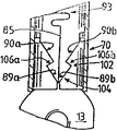
제6도는 제4도의 연결구를 180°회전시킨 배면도.6 is a rear view in which the connector of FIG. 4 is rotated 180 degrees.
제7도는 띠모양의 금속박판으로부터 슬리브를 타발 및 굴곡가공하여 제조하는 경우의 공정도.7 is a process chart for manufacturing by punching and bending a sleeve from a strip-shaped metal sheet.
제8도는 제1굴곡단계 후의 슬리브 말단을 제7도의 VIII방향에서 본 도면.FIG. 8 is a view of the end of the sleeve after the first bending step in the VIII direction of FIG.
제9도는 제1굴곡가공단계에 후속하는 제2굴곡가공단계후의 슬리브 단면을 제7도의 IX방향에서 본 도면.9 is a view of the cross section of the sleeve after the second bending step following the first bending step in the IX direction of FIG.
제10도는 최종 굴곡가공단계가 완료된 후의 슬리브 말단면을 제7도의 X방향에서 본 도면.10 is a view of the end face of the sleeve after the final bending step is completed in the X direction of FIG.
제11도는 쐐기형 돌출부와 여기에 대응하는 V자형의 절홈부를 갖춘 슬리브를 가진 연결구의 일부 발췌정면도로서 파이프를 절취한 상태도.11 is a partial cutaway front view of a connector having a sleeve having a wedge-shaped protrusion and a corresponding V-shaped cutout, wherein the pipe is cut away.
제12도는 제11도에 도시한 슬리브의 저부측 정면도.12 is a bottom front view of the sleeve shown in FIG.
제13도는 고정슬리브에 의해 나사가 조여지는 위치에서 고정볼트가 소실되지 않도록 고정볼트를 붙잡고 있는 연결구를 도시한 부분절단도.Figure 13 is a partial cutaway view of the connector holding the fixing bolts so that the fixing bolts are not lost in the position where the screws are tightened by the fixing sleeve.
* 도면의 주요부분에 대한 부호의 설명* Explanation of symbols for main parts of the drawings
1,54,70 : 연결구1,54,70: End Connection
2,67a,67b,77,103,104,55a,55b,92 : 요함부2,67a, 67b, 77,103,104,55a, 55b, 92
3,53a,53b,65a,65b,74,87,101,102 : 쐐기3,53a, 53b, 65a, 65b, 74,87,101,102: wedge
4,5,50,51,52,71,72 : 슬리브 7 : 조임나사4,5,50,51,52,71,72: Sleeve 7: Tightening screw
9,10,11 : 관통구 13: 결 합체9,10,11: through hole 13: coalescence
14 : 파이프 15 : 숄더14
16 : 턱16: jaw
25a,25b,26a,26b,27a,27b,33a,33b,34a,34b,35a,35b,75a,75b,76a,76b,89a,89b,90a,90b : 쐐기면25a, 25b, 26a, 26b, 27a, 27b, 33a, 33b, 34a, 34b, 35a, 35b, 75a, 75b, 76a, 76b, 89a, 89b, 90a, 90b
37a,37b,39a,39b,29a,29b,31a,31b,70a,80a,80b : 변37a, 37b, 39a, 39b, 29a, 29b, 31a, 31b, 70a, 80a, 80b
24 : 절개선 41a,41b,43 : 사이공간24: incision 41a, 41b, 43: interspace
57a,57b : 미세연결부 61,93,105a,105b : 톱니부57a, 57b:
63 : 분리선63: dividing line
본 발명은 연결구 특히, 어떤 구조물의 구멍안에서 접하여 고정가능하게 하므로서 인접하는 다른 구조물과의 결합을 용이하게 하는 연결구와 이러한 연결구의 제조방법에 관한 것이다.The present invention relates to a connector, in particular a connector that facilitates engagement with another adjacent structure by being able to contact and lock in a hole of a structure and a method of making the connector.
이런 종류의 연결구로서는 독일 특허제 3237468호로서 한개의 볼트와 두개의 쐐기형 슬리브로 되었으며, 볼트의 한쪽 끝은 밴드모양으로 되어 있고 다른 한쪽 끝은 그 단면이 나사모양이 형성되어 있어서 볼트를 태엽감듯이 돌림으로써 고정시킬 수 있는 연결구가 알려진 바 있다.This type of connector is German Patent No. 3237468, consisting of one bolt and two wedge-shaped sleeves, one end of which is band-shaped and the other end of which is screw-shaped so that the bolt is wound There is a known connector that can be fixed by turning.
이 연결구는 연결구를 결합체에 단단히 고정시킬 목적으로 고정나사로서 슬리브를 밀어 조이며 그리하면 쐐기 슬리브는 경사진 면을 따라서 미끄러져 들어가게 되고 원통형의 결합구멍으로 끼워들어가 방사상의 방향으로 벌어져 압접된다. 볼트의 밴드부분이 인접한 슬러브가 뒤로 미끄러지는 것을 방지하고 돌기부 쐐기의 첨단부에 배열되어 버팀목으로 받쳐진다. 돌기부가 모체 즉 결합체에 결합되면서 갈라지거나 적어지게 된다.This connector pushes and tightens the sleeve as a set screw for the purpose of holding the connector firmly to the assembly, whereby the wedge sleeve slides along the inclined surface and is inserted into the cylindrical engagement hole to be squeezed in the radial direction. The band portion of the bolt prevents the adjacent slab from slipping back and is arranged at the tip of the protrusion wedge to be supported by the crutch. As the protrusions are joined to the mother, that is, the union, they become cracked or reduced.
그리고 나팔모양의 슬리브 부재와 이 나팔모양의 슬리브 부재에 적어도 한군데 이상의 미세 연결부로 연결된 쐐기부재 및 이 쐐기부재를 너트라 하고 이 너트의 볼트를 결합시켜 볼트를 회전시키므로서 너트인 쐐기부재를 당겨 나팔모양의 슬리브부재 선단을 방사상의 방향으로 벌어지게 하여 슬리브부재 외면이 결합체의 내부공간에 밀접하게 결합되게 하여서 된 연결구가 영국특허 제1475839호로 알려진 바 있다. 그런데 이와 같은 연결구는 슬리브 부재의 쐐기부재를 제조함에 있어서 그 제조가 특히 곤란하여 제조비용이 과다한 결점이 있다.And the wedge member connected to the trumpet-shaped sleeve member and the trumpet-shaped sleeve member by at least one micro connection, and the wedge member is called a nut, and the nut of the wedge member is pulled out by rotating the bolt by engaging the bolt of the nut. A connector is disclosed in British Patent No. 1475839 in which the tip of the sleeve member is opened in the radial direction such that the outer surface of the sleeve member is closely coupled to the inner space of the assembly. However, such a connector has a drawback in that the manufacturing cost is particularly difficult in manufacturing the wedge member of the sleeve member.
또한 스위스 연방특허공고 제429317호에 기술된 연결구는 두개의 동일한 쐐기 슬리브로 형성되고, 쇄기슬리브는 결합체에 고정될 파이프의 말단부에 서로 경사진 슬라이딩 면을 겹쳐 맞추어 배치되는 것으로 이는 슬리브를 관통하는 고정나사가 결합체의 나사에 조여짐에 따라 양쪽방향의 쐐기 슬리브는(쐐기슬리브의 슬라이딩면과 반대측에 결합체 내지 볼트 헤드에 접해있기 때문에) 슬라이딩 면에서 서로 미끄러져 이로 인하여 파이프의 말단부 내면에 압력이 가해지고, 이에 따라 파이프의 말단부가 결합체와 결합하게 되어 있다.In addition, the connector described in Swiss Federal Patent No. 429317 is formed by two identical wedge sleeves, and the wedge sleeves are arranged by overlapping sliding surfaces inclined with each other at the distal end of the pipe to be fixed to the assembly, which is fixed through the sleeve. As the screw is tightened to the screw of the joint, the wedge sleeves in both directions slide (because they are in contact with the joint or bolt head on the opposite side of the sliding face of the wedge sleeve) and slide against each other on the sliding surface, thereby applying pressure to the inner surface of the distal end of the pipe. As a result, the distal end of the pipe is adapted to engage the assembly.
독일특허공고 제3,523,155호에 기재되어 있는 연결구는 상술한 연결구와는 종류가 다른 것으로, 확대가 가능한 슬리브로 형성된 하나의 슬리브를 가지며 이 슬리브는 체결용 보울트에 의해 슬리브내로 끼워 들어오도록 하는 쐐기부재에 의해 확대되도록 되어 있다.The connector described in German Patent Publication No. 3,523,155 is different from the connector described above, and has a single sleeve formed of an expandable sleeve, which has a wedge member which is inserted into the sleeve by a fastening bolt. It is intended to be enlarged by.
이러한 경우에도 체결용 보울트가 결합체내에 나사 결합되고, 확대가능한 슬리브가 결합체에 결합된다. 이 확개 가능한 슬리브는 확대됨으로써 결합체에 결합된 파이프의 단부 내면에 압접된다.In this case too, the fastening bolt is screwed into the assembly and the expandable sleeve is coupled to the assembly. This expandable sleeve is enlarged and pressed into the inner surface of the end of the pipe joined to the assembly.
이와 유사한 연결구가 독일특허공개공보 제3,528,744호에 의해 공지된 바 있다. 이것은 벽의 장부촉(dowel)으로 사용되고 있다. 이 연결구는 독일특허공고 제3,523,155호와는 달리 벽의 두께가 얇게 형성되고 파괴되는 부위를 갖는 제2의 확개슬리브와 서로 직경방향으로 대향하는 두개의 쐐기가 설치되어 있고, 그 쐐기는 벽의 구멍속에 끼워져 고정되어 있다.A similar connector is known from German Patent Publication No. 3,528,744. It is used as a dowel of the wall. Unlike the German Patent Publication No. 3,523,155, the connector is provided with a second expansion sleeve having a portion where the thickness of the wall is thinned and broken and two wedges facing each other in the radial direction. It is fitted inside and fixed.
미국특허 공고 제2,643,143에 기술된 포개어 끼우는 식의 고정구는, 지금 설명하고자하는 연결구와는 다른 유형으로, 하나의 파이프 밑부분에 쐐기형의 확대부분이 있는데 이것은 V자형으로, 파이프끝과 일체로 맞닺는 슬리브에 연속적인 절홈부가 형성되어 있고, 압력을 받지 않는 상태에서는 그 바깥 지름이 파이프의 지름과 꼭 같다. 그 슬리브는 압축 스프링에 의해서 파이프 내부로 밀어 넣어지는 체결용 볼트로 고정된다. 그리고 이 체결용 볼트는 압축 스프링의 대각선 방향으로 형성된 지렛대에 의해서 축을 중심으로 이동이 가능하다. 압축스프링이 헐거워지면 파이프의 끝부분이 두번째 파이프쪽으로 옮겨진다. 압축 스프링이 작동되면, 슬리브는 V자형의 절흠부로 당겨진다. 그래서 두번째 파이프관의 내부 벽속으로 당겨진다. 그러므로 각각의 두 파이프에 관하여 양자의 위치 변경이 방지될 수 있다.The nested fastener described in US Patent Publication No. 2,643,143, which is different from the connector described here, has a wedge shaped enlargement at the bottom of one pipe, which is V-shaped, which fits integrally with the pipe end. Has a continuous cutout in the sleeve, and under no pressure, its outer diameter is exactly the diameter of the pipe. The sleeve is secured with a fastening bolt that is pushed into the pipe by a compression spring. And this fastening bolt is movable about an axis by the lever formed in the diagonal direction of a compression spring. When the compression spring becomes loose, the end of the pipe is moved to the second pipe. When the compression spring is activated, the sleeve is pulled into the V-shaped cutout. So it is pulled into the inner wall of the second pipe. Therefore, the change of the position of both with respect to each two pipes can be prevented.
미국특허공고 제2,643,143호에 기술된 고정구는 파이프중 하나에는 복잡한 기계공정 과정이 필요하고 연결되는 두 파이프만 적용되는 방법이다. 상술한 모든 결합장치와 연결구는 강한 탄력에 의해서 삽입되거나 제조과정이 비경제적이다.The fixture described in U. S. Patent No. 2,643, 143 is a method in which one of the pipes requires a complex mechanical process and only two pipes are connected. All the coupling devices and connectors described above are inserted by strong elasticity or are uneconomical to manufacture.
그외의 연결장치(connecting advice)는 미국특허 제3,945,743호, 프랑스특허 제2,278,978호, 스위스특허 제488,120호 미국특허 제3,815,198호가 있다.Other connecting advices are U.S. Patent No. 3,945,743, French Patent No. 2,278,978, Swiss Patent No. 488,120 and US Patent No. 3,815,198.
본 발명은 이와 같은 종래의 연결구에 있어서의 결점들 특히, 제조상의 결점을 극복하며 간단하고 경제적인 방법으로 제조하고 신속하게 조립할 수 있는 연결구를 제공할 수 있도록 한 것이다.The present invention overcomes the drawbacks of such a conventional connector, in particular, a manufacturing defect and can provide a connector that can be manufactured and assembled quickly and in a simple and economical manner.
이와 같은 본 발명을 첨부된 도면에 의하여 설명하면 다음과 같다.Referring to the present invention as described above is as follows.
제1도에 도시된 바와 같이 연결구(1)은 원통형 슬리브(4,5)와 조임나사(7), 그리고 공모양의 결합체(13)으로 구성되며, 원통형 슬리브(4,5)는 V자형의 요함부(2)와 쐐기(3)을 가지며, 결합체(13)은 도합 세개의 나사 관통구를 가지는데 이 관통구(9,10,11)에는 나사홈이 형성되어 있어 조임나사(7)의 나사머리를 돌립으로서 조임나사(7)가 이 관통구로 들어갈 수 있도록 하였다. 연결구(1)은 파이프(14)와 결합체(13)을 고착시키기 위한 연결수단이다. 슬리브(4,5)를 더 명확하게 도시하기 위하여 파이프(14)는 이를 절취도시하였다.As shown in FIG. 1, the connector 1 is composed of
조임나사(7)에는 좁은 폭을 가지며 나사와 동축상인 숄더(15)를 형성시켰으며, 숄더(15)의 단부 즉, 나사몸체의 단부방향측에 턱(16)을 형성시켰다. 그리하여 슬리브(5)의 단부를 숄더(15)에 끼우고 슬리브(5)의 단부가 숄더(15)를 축으로 하여 회전가능하게 하며 또한 슬리브(5)가 턱(16)에 걸리어 자의로 조임나사(7)로부터 빠져나오지 아니하게 한다. 따라서, 조임나사(7)은 슬리브(5)에 분리되지 않게 결합된다. 조임나사(7)의 나사부는 관통구(9,10,11)에 형성되어 있는 나사부와 꼭 맞도록 형성되었다. 각각의 육각형의 소켓(18,19)는 나사의 머리 부분과 끝부분에 다 설치되어 있다.The tightening
제1도에 도시된 바와 같이 슬리브(4)의 후면에는 홈(21)이 형성되어 있는데 이는 전면에 형성된 요함부(2)와 위치상 반대방향에 설치되었으며 슬리브(5)에는 돌기(23)이 형성되어 이 홈에 맞물리도록 되어 있는데 모두 슬리브(4,5)의 축의 방향으로 뻗어 있다.As shown in FIG. 1, a
전체 슬리브(5)와 쐐기(3)은 절개선(24)에 의하여 잘려져 있는데 이 절개선(24)은, 후술하는 바와 같이, 제조과정에서 생성되는 것이다. 확대부(3)은 세 쌍의 쐐기면(25a,25b,26a,26b,27a,27b)를 가지고 있는데 각 쌍(25,26,27)의 a면과 b면은 확대부(3)의 중심선을 중심으로 하여 대칭이 되게 형성되어 있다. 한 쌍의 쐐기면(25)과 다른 쌍의 쐐기면(26)은 한쌍의 변(29)으로 분할되어 있으며 각 변(29a,29b)은 슬리브(4,5)의 길이 방향과 평행하게 형성되어 있고, 또 한쌍의 쐐기면(26)과 다른 쌍의 쐐기면(27) 역시 다른 한쌍의 변(31)으로 분할되고 각 변(31a,31b) 또한 슬리브(4,5)의 길이방향에 평행하게 형성되었으며 쐐기면(27a,27b)은 등거리상의 정점에서 적당한 각도를 이루며 만나도록 형성되었다.The
도시한 바와 같이 슬리브(4)의 세쌍의 쐐기면(33,34,35)는 슬리브(5)의 세쌍의 쐐기면(25,26,27)과 똑같은 각도로 형성되고 슬리브(4)의 변(37a,37b,39a,39b)과 슬리브(5)의 변(29a,29b,31a,31b)은 적당한 간격으로 떨어져서 형성되었는데 변(29,37)은 사이간격(41a/b)에 의해서, 변(31,39)은 사이간격(43)에 의해서 적당한 공간을 두고 분리되어 있다.As shown, the three pairs of wedge surfaces 33, 34, 35 of the sleeve 4 are formed at the same angle as the three pairs of wedge surfaces 25, 26, 27 of the
쐐기면(25a/33a,25a/33b,26a/34a,26a/34b,27a/35b,27b/35b)이 후술하는 연결구(70)의 제조공정에 있어서의 타발공정과 유사한 타발공정으로 인해 형성된 미세연결구에 의해서 맞붙게 되므로 두개의 슬리브(4,5)는 서로 분리되지 않게 결합되며, 또한 슬리브(5)의 연결된 조임나사 또한 분리되지 않게 된다. 따라서 미세연결부는 조임 나사(7)을 조일때에만 의도적인 파괴가 이루어지게 된다. 조임나사(7)을 조여 확개부(3)을 요함부(2)로 밀어넣는 힘이 커질수록 각각의 사이공간(41a,41b,43)이 커지게 되고 슬리브(4)가 확개되어 파이프(14)의 내벽에 가하는 압력이 커지게 된다. 압력을 받지 않는 상태에서, 슬리브(4)의 지름은 슬리브(5)의 지름과 꼭 같으며 따라서 슬리브(4,5)는 파이프(14)속으로 여유있게 삽입된다.Fine formed by the punching process similar to the punching process in the manufacturing process of the
슬리브(4,5)는 평평한 금속판으로 형성시키되 금속판을 타발하여 형성시키고 슬리브 모양으로 절곡형성시킨다. 이렇게 하여 파이프 내부에서의 슬리브(4,5)의 체결 작용은 조임나사(7)에 의해서 조절될 수 있도록 하였으므로 조임나사(7)을 결합체(13)으로부터 완전히 제거한 다음에야 연결구(1)을 파이프의 끝부분으로부터 빼어낼 수 있다. 그 두개의 물체를 연결함에 있어서 그 연결상태가 극히 완고해야 하지 아니한다면 상술한 바와 같이 쐐기면과 요흠부를 다수쌍 형성시키지 아니하고 쐐기와 요홈부를 한쌍씩만으로 형성시킬 수도 있다. 그러나 그러한 경우에 제조과정에서 다음과 같은 문제가 발생할 수 있다. 즉, 미세연결부가 판체를 구부리는 과정에서 이미 파열되어 연결구의 각 부품들이 따로따로 분리될 염려가 있다.The
제1도에 도시된 바와 같은 슬리브(4,5)는 제2도에 도시된 바와 같은 슬리브(50,51,52)로 형성시킬 수도 있다.The
즉, 제2도에 도시된 바와 같이 슬리브(50,51)은 쐐기(53a,53b)를 가지고 있는데 이는 슬리브(52)의 요함부(55a,55b)에 맞물리도록 형성되었다. 두개의 또 다른 쐐기(65a,65b)는 슬리브(52)의 양단에 서로 반대방향을 향하여 배열되어 있다. 또한 제3도에 도시된 바와 같이 쐐기(65a,65b)는 슬리브(50,51)에 있는 요함부(67a,67b)에 각각 맞물리게 형성되었다.That is, as shown in FIG. 2, the
제1도에 도시된 바와 같은 연결구(1)에서와 마찬가지로, 조립되기전에 제조상태에서는 쐐기(53a,53b)가 미세연결부(57a,57b)에 연결되어 있고, 조여지지 않은 상태에서는 요함부(55a,55b)는 미세연결부(57a,57b)를 사이에 두고 길이방향의 구멍(59)와 떨어져 있다. 파이프(14)를 조립한 후 조임나사(7)을 조임으로서 미세연결부(57a,57b)는 쐐기(53a,53b)에 의해서 파열되고 요함부(55a,55b)는 길이방향의 구멍(59)과 연통되며 따라서 슬리브(52)는 벌어진다.As in the connector 1 as shown in FIG. 1, the
제3도에 도시된 바와 같이 슬리브(52)에는 톱니결합부(61)이 형성되어 있는데 톱니결합부(61)는 돌기부와 이에 대응하는 오목부로 구성되어 있고 돌기부와 오목부는 서로 서로 맞물려 있다. 따라서 미세연결부(57a,57b)가 파괴된 후에 슬리브(52)의 양면은 톱니결합부(61)에 의해서만 결합되고 상술한 바와 같이 벌어진 슬리브(52)는 파이프(14)의 내벽으로 압력을 가하게 되지만 톱니결합부(61)에 의해서 견고히 맞물려있으므로 분리될 우려는 없다. 또한 톱니결합부(61)의 길이 방향쪽 양단부에는 분리선(63)으로 분할된 쐐기(65a,65b)가 형성되어 있다. 그리하여 쐐기(65a,65b)가 슬리브(50,51)을 벌어지게 한다.As shown in FIG. 3, the
요컨대, 파이프(14)에 설치한 연결구(54)에 있어서, 세개의 슬리브(50,51,52)는 조임나사(7)을 조임으로서 미세연결부가 파열됨과 동시에 쐐기(53a)가 요함부(55a)로 전진하게 되고 요함부(55a)는 길이방향의 구멍(59)과 연통되면서 벌어진다. 벌어진 슬리브(52)는 서서히 파이프(14)의 내벽에 압력을 가하게 된다. 마찬가지로 쐐기(65a,65b)는 슬리브(50,51)에 있는 요함부(65a,67b)를 벌리게 되고 그리하여 벌어진 슬리브(50,51)는 파이프(14)의 내벽에 압력을 가하게 되는 것이다. 4개의 쐐기(53a,53b,65a,65b)는 슬리브(50,51,52)를 외방으로 벌리어 파이프(14)의 내벽에 균일하게 압접되게 한다.In other words, in the
제 4,5,6도에서는 슬리브(71,72)로 구성된 또 다른 실시예인 연결구(70)를 도시하였다. 제4도에서는 슬리브(71,72)를 도시하였는데 이것은 제1도에 도시한 슬리브(4,5)와 유사한 기능을 가지나 제1도에 도시된 슬리브(4)와는 달리 슬리브(71)은 요함부(77)에 단지 두쌍의 쐐기면(79a,79b,81a,80b)만이 형성되어 있다.4, 5, and 6 show another embodiment of the
슬리브(5)와 마찬가지로 슬리브(72)는 조임나사(7)에 형성시킨 숄더(15)에 결합되는 상단부가 내향으로 절곡되어 턱(16)을 감싸도록 형성시킨다. 그리하여 슬리브(72)의 상단은 숄더(15)를 여유를 두고 둘러싸게 되어 특별한 힘이 가해지지 않는 한 조임나사(7)가 슬리브(72)로부터 빠지지 아니하게 된다. 각 슬리브의 쐐기와 V자형 요함부는 서로 정확히 맞물릴 수 있도록 상반되는 형상으로 형성되었다.Like the
제5도는 제4도의 연결구(70)을 90도 회전시킨 모습을 도시한 것이다. 슬리브(71,72)를 더 명확하게 도시하기 위해서 제4-6도에서 파이프(14)는 이를 절취도시하였다. 슬리브(71)은 두개의 돌출부(제5도에서는 하나의 돌출부 81만 도시하였음)를 가지고 있는데 이것은 슬리브(72)의 수납부(82)에 맞물리게 형성되었다. 돌출부(81) 및 수납부(82)는 제5도에서 도시되지 않은 또 다른 돌출부 및 수납부와 쐐기(74)를 중심으로 좌우대칭적으로 위치하고 있다. 그러나 그것은 이하에서 설명하는 기능상의 문제에서 반드시 필요한 것은 아니다. 공간부(84)는 돌출부(81)의 위끝부분과 수납부(82)의 바닥부분에 위치한다. 돌출부(81)은 위쪽으로 벌어져 있고 수납부(82)는 바닥쪽으로 벌어져 있다. 그리하여 돌출부(81)와 수납부(82)는 서로 분리되지 않게 맞물리면서 한편으로는 공간부(84)의 폭만큼은 이동이 가능하다.5 is a view showing the
제6도는 제4도에 도시된 연결구(70)을 180도 회전시킨 모습을 도시한 것이다. 길이방향으로 난 절개선(85)는 슬리브(72)의 쐐기(87)의 가운데를 분할하고 슬리브(72)의 두쌍의 쐐기면(89a,89b,90a,90b)는 두쌍의 쐐기면(75a,75b,76a,76b)와 똑같은 길이와 각도로 디자인되었다. 길이방향으로 난 절개선(85)의 선상에는 돌기부와 이에 대응하는 오목부가 형성되어 있는데 이는 제3도에 도시한 슬리브(52)에서와 마찬가지의 기능을 가진다. 조임나사(7)을 조이면 쐐기(74)는 슬리브(72)를 벌리고 쐐기(87)은 슬리브(71)를 벌리므로서 슬리브(72)는 파이프(14)의 내벽에 균일하게 압접된다.6 is a view showing the
제7도에서는 제4도 내지 제6도에서 도시된 연결구(70)의 제조공정이 도시되었다. 즉, 제7도는 연결구(70)를 제조하는 단계별 공정을 (a) 공정에서 (e)공정까지에 걸쳐 나타내었다. (f)는 슬리브(71,72)가 절곡되기 시작한 모습을 보여주고 있는데 이를 VIII의 방향에서 바라본 모습을 제8도로 도시하였다. (g)는 슬리브(71,72)가 좀더 절곡된 모습을 보여주고 있는데 이를 IX의 방향에서 바라본 모습을 제9도로 도시하였다.(h)는 슬리브(71,72)가 완전히 절곡되어 톱니결합부(93)에 의해서 완전히 맞물려 있는 모습을 보여주고 있는데 이를 X의 방향에서 바라본 모습을 제10도로 도시하였다.In FIG. 7, a manufacturing process of the
(a) 공정은 금속판(95)에 네개의 공간부(84)와 판체이송용구멍(97)(몇개의 구멍을 더 사용하는 것도 가능함)이 천공되는 공정을 나타내었는데, 여기에 도시되지는 않았으나 판체이송용구멍에 핀치 꽂혀 있어 금속판을 다음 공정으로 이송하게 된다.(a) The process showed a process in which four
(b) 공정은 슬리브(71,72)의 양쪽 가장자리를 절단함으로서 톱니결합부(93)의 돌기부 및 오목부를 형성함과 동시에 연결부(98)을 형성한다.The step (b) cuts both edges of the
(c) 공정은 슬리브소재(99,100)의 분리선을 따라 절단하여 슬리브(71,72)의 펼쳐진 모습을 완성한다. 이때 슬리브소재(99,100)의 양면은 여전히 붙어 있는 상태다. (d)와 (e)공정에서는 아무런 작업도 시행되지 않지만 (c) 공정의 타발공정에 의해서 금속판체로부터 어긋난 슬리브소재(100)가 다시 평평하게 정돈되게 한다(정리공정). 이러한 공정중에 있어서도 물론 슬리브소재(99,100)들은 서로 연결되어 있다. 그리고 (d)공정은 정리공정인 (e)공정과 타발공정인 (c)공정을 구분지우는 기능을 가지기도 한다.(C) process is cut along the separation line of the sleeve material (99,100) to complete the unfolded appearance of the sleeve (71,72). At this time, both sides of the sleeve material (99,100) is still attached. No work is carried out in steps (d) and (e), but the sleeve material 100, which is displaced from the metal plate body by the punching process of step (c), is again flattened (arrangement step). Even during this process, the sleeve materials 99 and 100 are connected to each other. And (d) process has the function of distinguishing process (e) which is a sorting process from process (c) which is other process.
(f) 공정은 슬리브(71,72)를 처음으로 절곡하기 시작하여 슬리브소재(99,100)를 제8도에서 도시한대로 그 끝부분을 구부린다. 두번째 구부리는 작업은 (g)에서 수행된다. 이와 같은 둘째번 구부리는 작업은 슬리브소재를 제9도에서 도시한 바와 같이 구부리게 되며, 완전히 구부려진 후에는 연결부(96)는 절단된다.(f) The process begins to bend the
(h) 공정은 슬리브소재(99,100)을 절곡시켜 완전한 슬리브(71,72)를 형성하며 완전히 절곡된 후에는 톱니결합부(93)의 돌기부와 오목부가 꼭 맞물리게 된다.The process (h) is to bend the sleeve material (99,100) to form a complete sleeve (71,72), and after the complete bend the projection and the concave portion of the
이와 같은 제조방법에 의하여 두 개의 슬리브(71,72)는 함께 제조되어진다. 파이프(14)의 내부에 있는 조임나사(7)에 의해서만 슬리브(71,72)사이의 분리선이 완전히 분리된다. 양 슬리브(71,72)는 돌출부(81)와 수납부(82)가 맞물림으로서 서로 떨어지지 않도록 맞물리게 되는데, 그것들을 슬리브(71,72)를 벌려 슬리브(71,72)가 파이프(14)내벽으로 단단히 압력을 가하는 범위내에서 공간부(84)의 폭만큼 길이방향으로의 이동이 가능하다.By this manufacturing method, the two
슬리브소재를 절곡하는 (f),(g),(h)공정중, 두개의 슬리브(71,72)는 분리선을 따라 접하여져 있으며, 슬리브(71,82)의 쐐기(74,87)와 요함부(77,92)는 분리되지 아니한다. 이때까지는 쐐기(74,87)와 요함부(77,92)의 분리선이 아직 잘려지지 아니한다.During the (f), (g) and (h) bending of the sleeve material, the two
슬리브(4,5;50,51,52;71,72)는 금속대신에 탄성있는 다른물질로 형성시키는 것이 가능하다. 연결구가 꼭 1회만 사용되어 진다면 탄성이 없는 물질로도 형성시킬 수 있다.The
또한 서로 어긋나지 않게 평평히 배열된 슬리브가 서로 분리되지 않게 하기 위하여 슬립(71,72)가 돌출부(81)와 수납부(82)에 의해 결합되어 있는 것과 마찬가지로 슬리브(4,5; 50,51,52)들도 돌출부와 수납부에 의해 결합되어 있다.In addition, the
또한 쐐기와 요함부를 제11도와 제12도에 도시한 바와 같이 톱니모양으로 된 톱니부(105a,105b,106a,106b)로 형성시켜 결합시키는 방법도 가능하다. 즉, 제4도 내지 제6도에서 도시된 슬리브(71,72)의 쐐기(74,87)을 각각 제11도와 제12도에 도시된 바와 같은 쐐기(101,102)로 변경시키고, 또한 V자형 요함부(77,92)는 각각 V자형 요함부(103,104)로 변경하여 형성시킨다. 이들 톱니부(105a,105b,106a,106b)는 요함부(103)의 가장자리와 쐐기(101)의 사이에서 또는 요함부(104)와 쐐기(102)의 사이에서 상술한 미세 연결부와 유사한 역할을 한다. 미세연결부나 톱니부는 구부리는 과정에서 맞닿아 있는 두개의 대향하는 슬리브가 쐐기형 표면을 따라 미끄러지는 것을 방지하고 슬리브끼리를 고정시키는 역할을 한다. 다만 미세 연결부와 비교할때 톱니부(105a,105b,106a,106b)가 가지는 장점은 연결구(70)을 반복적으로 사용하더라도 분리선 부위에 있어서의 형의 전달 가능성이 더 크다는 점이다. 그러나 이 톱니부는 슬리브를 결합시키기 위한 절대적인 요소는 아니다. 왜냐하면 이 기능은 돌출부(81)와 수납부(82)에 의해서도 충분히 이루어질 수 있기 때문이다.In addition, as shown in Figs. 11 and 12, the wedge and the recesses can be formed by joining by forming
조임나사의 턱(16)을 형성하고 여기에 슬리브의 상단을 절곡시키는 대신에 나사의 몸체와 슬리브(4,5; 50,51,52; 71,72)의 내벽 사이에 별도의 체결도구를 사용할 수도 있다. 예컨데 단면이 U자형인 구멍 뚫린 판체로 볼트 몸체와 슬리브 내벽 사이를 탄력적으로 조여서 U자형 판체의 한쪽 다리로는 볼트 몸체에 압박을 가하고 다른 한쪽으로는 슬리브(4,5,50,52,71,72)에 압박을 가하게 한다. 이러한 경우에 조임나사(7)에 슬리브 내부의 중앙에 고정되므로 파이프(14)와 결합체(13)의 연결시 조임나사(7)을 용이하게 결합체(13)로 조립할 수 있는 장점이 있다.Instead of forming the
또한 탄성이 있는 구멍뚫린 판체를 사용하거나 나사머리에 슬리브의 상단을 구부려 결합하는 대신에 제13도에 도시된 체결용 슬리브(107)을 사용할 수도 있다. 체결용 슬리브(107)은 그 양단에 체결용고리(109a,109b)가 형성되어 있어서 슬리브(71,72)에 압박을 가하도록 되어 있다. 체결용 슬리브(107)을 조임나사(7)의 몸체에 적은 압박을 가하면서 결합되어 있으며, 슬리브(71,72)의 내부에서 조임나사(7)을 슬리브와 분리되지 않도록 고정시키는 한편, 조임나사를 결합(13)에 형성된 관통구 중 하나와 용이하게 조립할 수 있는 위치에 나사를 고정시킨다. 이웃하는 양 슬리브를 서로 결합시키고 그 슬리브(4,5,50,51,52,71,72)를 조임나사(7)에 연결시키므로서 연결구(1,54,70)의 모든 부품이 각자 제위치에서 분리되지 않게 결합되어 연결구는 하나의 단독부품으로 파이프단부로 삽입된다.Alternatively, a
본 발명의 연결구는 그 조립 시간을 단축했다는 점에서 기존의 연결구와 본질적인 차이점이 있다. 연결구(1,54,70)은 조이고 풀어주는 과정을 반복적으로 행함에 있어서 쉽게 헐거워질 수 있도록 하여 결합체(13)에 파이프(14)이외의 다른 파이프와의 재결합이 가능할 수 있도록 하였다.The connector of the present invention is essentially different from the existing connector in that the assembly time is shortened. The connector (1, 54, 70) can be easily loosened by repeating the tightening and loosening process to enable the recombination of the
본 발명의 제조방법에 따라 슬리브(4,5,50,51,52,71,72)는 얇은 금속판(95)를 사용하므로서 매우 경제적으로 생산할 수 있을 뿐아니라 타발공정에 의하여 양질의 쐐기면을 형성시킬 수 있어 쐐기면에서의 미끄러짐을 좋게 하기 위한 재가공을 필요로 하지 아니하게 되는 효과가 있다.According to the manufacturing method of the present invention, the
또한 연결구(1,54,70)의 구조와 생산과정에 있어서는 위 연결구의 모든 슬리브(4,5,50,51,52,71,72)는 동시에 제조되고 제조과정에서 이미 양 슬리브는 맞물리도록 생상되는 것을 특징으로 한다.In addition, in the structure and production process of the
조임나사(7)은 슬리브(4,5,50,51,52,71,72)중 하나와 분리되지 않게 결합되므로 결합체(13)과의 조립 또한 신속 용이하게 행하여질 수 있게 한다.The tightening
조임나사의 조이는 힘을 최소화하면서 파이프(14)의 내부에 있는 슬리브(4)의 체결작용을 최대로 할 수 있는 이유는 전체길이에 분산된 쐐기면(25,26,27)에 의해서 쐐기(3)이 요함부(2)에 압력을 가하여 슬리브를 분리 확장시키기 때문이다. 쐐기(3)에 의해서 요함부(2)가 벌어지면서 원통형 슬리브(4)는 전체 원통에 걸쳐 동일한 힘이 가해지므로 슬리브는 벌어지게 되고 벌어진 슬리브(4)의 외벽이 파이프(14)의 내벽에 접하게 되어 거대한 마찰력이 생성되어 고정되는 것이다.The reason why the tightening action of the sleeve 4 in the inside of the
제2,3,4,5,6도에 도시된 슬리브(71,72,51,52,50)도 이와 동일한 원리에 의해 고정된다. 조임나사(7)를 작은 힘으로 조일 수 있는 이유는 슬리브(4,5,50,51,52,71,72)가 얇은 금속판으로 형성되어 있고, 쐐기가 이러한 얇은 금속판을 벌릴 수 있을 만큼의 힘으로 조이면 되기 때문이다. 그리고 조임나사(7)를 조이는 힘의 대부분은 슬리브를 파이프의 내벽에 압박하는데 사용된다.The
이와 같은 연결구는 선반이나 판매대, 그리고 기타 물건등을 걸어주는 걸이 그리고 이와 유사한 구조를 갖는 파이프 제조시에 유용하게 사용할 수 있으며 또한 문을 설치할때 문틀의 구멍에 넣는 소위 확장 장부촉으로도 사용이 가능하다.These connectors can be useful for the manufacture of hooks for shelves, shelves, and other objects, as well as for the manufacture of pipes of similar construction, and also as so-called extended dowels that are inserted into the openings of the door frames when installing the doors. .
Claims (9)
Applications Claiming Priority (3)
| Application Number | Priority Date | Filing Date | Title |
|---|---|---|---|
| CH2022/89-0 | 1989-05-30 | ||
| CH202289 | 1989-05-30 | ||
| SG110893A SG110893G (en) | 1989-05-30 | 1993-10-02 | Fixing element |
Publications (2)
| Publication Number | Publication Date |
|---|---|
| KR900018550A KR900018550A (en) | 1990-12-21 |
| KR930002421B1 true KR930002421B1 (en) | 1993-03-30 |
Family
ID=25689288
Family Applications (1)
| Application Number | Title | Priority Date | Filing Date |
|---|---|---|---|
| KR1019900007647A KR930002421B1 (en) | 1989-05-30 | 1990-05-26 | Connector |
Country Status (11)
| Country | Link |
|---|---|
| EP (1) | EP0400345B1 (en) |
| JP (1) | JPH0314901A (en) |
| KR (1) | KR930002421B1 (en) |
| AT (1) | ATE93015T1 (en) |
| DD (1) | DD294761A5 (en) |
| DE (1) | DE59002267D1 (en) |
| DK (1) | DK0400345T3 (en) |
| ES (1) | ES2045629T3 (en) |
| GR (1) | GR3008890T3 (en) |
| HK (1) | HK120593A (en) |
| SG (1) | SG110893G (en) |
Families Citing this family (11)
| Publication number | Priority date | Publication date | Assignee | Title |
|---|---|---|---|---|
| GB2254901B (en) * | 1991-04-20 | 1994-10-19 | Rawlplug Co Ltd | Anchor bolts |
| GB2264517A (en) * | 1992-01-31 | 1993-09-01 | Ergotrak Building Systems Ltd | Connector for e.g. building modules |
| KR940010455B1 (en) * | 1992-09-24 | 1994-10-22 | 김영길 | Copper alloy and making method thereof |
| DE4316808C2 (en) * | 1993-05-19 | 1996-09-12 | Manfred Stroppe | Clamping piece for pipe elements |
| CH687665A5 (en) * | 1994-05-02 | 1997-01-31 | Schaerer Soehne Ag Usm U | Frame construction with several staff members. |
| DE29506323U1 (en) * | 1995-04-12 | 1995-06-29 | Rosenkoetter Torsten Dipl Kauf | Node connection for support systems |
| JP3550233B2 (en) * | 1995-10-09 | 2004-08-04 | 同和鉱業株式会社 | Manufacturing method of high strength and high conductivity copper base alloy |
| EP1159891A1 (en) | 2000-05-29 | 2001-12-05 | Swatch Ag | Modular framework for furniture and handles for transport of such furniture |
| CN100581413C (en) | 2003-04-22 | 2010-01-20 | 杜科瑞士股份公司 | Connecting element and frame system |
| CH702410B1 (en) | 2007-09-10 | 2011-06-30 | Heinz Kelderer | Connecting apparatus for a pipe system, as well as piece of furniture with such a pipe system. |
| EP2865902A1 (en) | 2013-10-28 | 2015-04-29 | Peter Wey | Connecting device for a construction system and construction system |
Family Cites Families (6)
| Publication number | Priority date | Publication date | Assignee | Title |
|---|---|---|---|---|
| GB191411612A (en) * | 1914-05-11 | 1914-08-20 | Ira Boutell Malaby | Improvements in Wall-plugs, or Sockets. |
| US1429298A (en) * | 1921-09-23 | 1922-09-19 | Henry B Newhall | Bolt anchor |
| GB1475839A (en) * | 1976-03-16 | 1977-06-10 | Plas Plugs Ltd | Fixing devices |
| DE3237468A1 (en) * | 1982-05-29 | 1984-04-12 | Artur Dr.H.C. 7244 Waldachtal Fischer | Attachment element |
| DE3426288C2 (en) * | 1984-07-17 | 1993-10-14 | Toge Duebel A Gerhard Gmbh | Expansion dowels made of sheet metal |
| DE3528744A1 (en) * | 1985-08-10 | 1987-02-12 | Stumpp & Kurz | Device for attaching an object to a wall or the like |
-
1990
- 1990-05-02 ES ES90108304T patent/ES2045629T3/en not_active Expired - Lifetime
- 1990-05-02 DE DE9090108304T patent/DE59002267D1/en not_active Expired - Lifetime
- 1990-05-02 AT AT90108304T patent/ATE93015T1/en not_active IP Right Cessation
- 1990-05-02 DK DK90108304.8T patent/DK0400345T3/en not_active Application Discontinuation
- 1990-05-02 EP EP90108304A patent/EP0400345B1/en not_active Expired - Lifetime
- 1990-05-25 DD DD90340969A patent/DD294761A5/en unknown
- 1990-05-26 KR KR1019900007647A patent/KR930002421B1/en not_active IP Right Cessation
- 1990-05-30 JP JP2138628A patent/JPH0314901A/en active Granted
-
1993
- 1993-08-30 GR GR920402810T patent/GR3008890T3/el unknown
- 1993-10-02 SG SG110893A patent/SG110893G/en unknown
- 1993-11-04 HK HK1205/93A patent/HK120593A/en not_active IP Right Cessation
Also Published As
| Publication number | Publication date |
|---|---|
| DD294761A5 (en) | 1991-10-10 |
| DK0400345T3 (en) | 1993-09-27 |
| JPH0555722B2 (en) | 1993-08-17 |
| EP0400345B1 (en) | 1993-08-11 |
| GR3008890T3 (en) | 1993-11-30 |
| KR900018550A (en) | 1990-12-21 |
| ATE93015T1 (en) | 1993-08-15 |
| ES2045629T3 (en) | 1994-01-16 |
| DE59002267D1 (en) | 1993-09-16 |
| HK120593A (en) | 1993-11-12 |
| SG110893G (en) | 1994-02-25 |
| JPH0314901A (en) | 1991-01-23 |
| EP0400345A1 (en) | 1990-12-05 |
Similar Documents
| Publication | Publication Date | Title |
|---|---|---|
| KR930002421B1 (en) | Connector | |
| US3881753A (en) | Fastener mechanism | |
| US6874971B2 (en) | Connector for tube and connected tubular structure | |
| US5567081A (en) | Joint forming device | |
| US6299397B1 (en) | Double ended expansion fastener | |
| US4190375A (en) | Fastening device | |
| US5605410A (en) | Connecting mechanism for tubular frame members | |
| US5029907A (en) | Band for effecting a seal | |
| US5846039A (en) | Positive lock rivet | |
| US4826379A (en) | Push nuts and push-nut fasteners | |
| HU213073B (en) | Arrangement for connecting the edges of platelike parts | |
| JP2002531734A (en) | Hollow profile rod | |
| HU224517B1 (en) | Device for producing a pressure-tight pipe coupling | |
| DE19622069A1 (en) | Housing for a device for forming a connection | |
| US5238343A (en) | Connecting element | |
| US20040155464A1 (en) | Coupling for connection of a tube or hose by pushing-in | |
| EP0941444B1 (en) | Heat exchanger tube and method of manufacturing same | |
| DE19622072A1 (en) | Device for forming a connection | |
| US3574378A (en) | Strengthening insert and fastener for tubular constructions | |
| JPH0781569B2 (en) | Expansion plug | |
| EP0638752A1 (en) | Pipe connector | |
| WO1988007282A1 (en) | A profiled section joining device | |
| KR200198059Y1 (en) | A fitting for high presure hose | |
| EP0498110B1 (en) | Improved band with slotted wedge cams | |
| GB2219060A (en) | A connector |
Legal Events
| Date | Code | Title | Description |
|---|---|---|---|
| A201 | Request for examination | ||
| E902 | Notification of reason for refusal | ||
| G160 | Decision to publish patent application | ||
| O035 | Opposition [patent]: request for opposition | ||
| O122 | Withdrawal of opposition [patent] | ||
| E701 | Decision to grant or registration of patent right | ||
| O073 | Decision to grant registration after opposition [patent]: decision to grant registration | ||
| GRNT | Written decision to grant | ||
| FPAY | Annual fee payment |
Payment date: 20090218 Year of fee payment: 17 |
|
| LAPS | Lapse due to unpaid annual fee |