EP2865902A1 - Connecting device for a construction system and construction system - Google Patents
Connecting device for a construction system and construction system Download PDFInfo
- Publication number
- EP2865902A1 EP2865902A1 EP20130190410 EP13190410A EP2865902A1 EP 2865902 A1 EP2865902 A1 EP 2865902A1 EP 20130190410 EP20130190410 EP 20130190410 EP 13190410 A EP13190410 A EP 13190410A EP 2865902 A1 EP2865902 A1 EP 2865902A1
- Authority
- EP
- European Patent Office
- Prior art keywords
- clamping
- bearing
- connecting device
- head
- holding
- Prior art date
- Legal status (The legal status is an assumption and is not a legal conclusion. Google has not performed a legal analysis and makes no representation as to the accuracy of the status listed.)
- Withdrawn
Links
- 238000010276 construction Methods 0.000 title description 8
- 230000008878 coupling Effects 0.000 claims description 8
- 238000010168 coupling process Methods 0.000 claims description 8
- 238000005859 coupling reaction Methods 0.000 claims description 8
- 239000011248 coating agent Substances 0.000 claims description 4
- 238000000576 coating method Methods 0.000 claims description 4
- 239000002184 metal Substances 0.000 claims description 4
- 238000005192 partition Methods 0.000 claims 1
- 239000000463 material Substances 0.000 description 4
- 125000006850 spacer group Chemical group 0.000 description 4
- 238000005253 cladding Methods 0.000 description 3
- 238000009434 installation Methods 0.000 description 3
- 238000000034 method Methods 0.000 description 2
- 230000000284 resting effect Effects 0.000 description 2
- 240000003517 Elaeocarpus dentatus Species 0.000 description 1
- 241001295925 Gegenes Species 0.000 description 1
- 238000004026 adhesive bonding Methods 0.000 description 1
- 230000000295 complement effect Effects 0.000 description 1
- 230000006835 compression Effects 0.000 description 1
- 238000007906 compression Methods 0.000 description 1
- 239000003292 glue Substances 0.000 description 1
- 238000003780 insertion Methods 0.000 description 1
- 230000037431 insertion Effects 0.000 description 1
- 239000011810 insulating material Substances 0.000 description 1
- 238000009413 insulation Methods 0.000 description 1
- 230000010354 integration Effects 0.000 description 1
- 238000004519 manufacturing process Methods 0.000 description 1
- 239000000203 mixture Substances 0.000 description 1
- 230000002093 peripheral effect Effects 0.000 description 1
- 239000002023 wood Substances 0.000 description 1
Images


Classifications
-
- F—MECHANICAL ENGINEERING; LIGHTING; HEATING; WEAPONS; BLASTING
- F16—ENGINEERING ELEMENTS AND UNITS; GENERAL MEASURES FOR PRODUCING AND MAINTAINING EFFECTIVE FUNCTIONING OF MACHINES OR INSTALLATIONS; THERMAL INSULATION IN GENERAL
- F16B—DEVICES FOR FASTENING OR SECURING CONSTRUCTIONAL ELEMENTS OR MACHINE PARTS TOGETHER, e.g. NAILS, BOLTS, CIRCLIPS, CLAMPS, CLIPS OR WEDGES; JOINTS OR JOINTING
- F16B12/00—Jointing of furniture or the like, e.g. hidden from exterior
- F16B12/10—Jointing of furniture or the like, e.g. hidden from exterior using pegs, bolts, tenons, clamps, clips, or the like
- F16B12/12—Jointing of furniture or the like, e.g. hidden from exterior using pegs, bolts, tenons, clamps, clips, or the like for non-metal furniture parts, e.g. made of wood, of plastics
- F16B12/20—Jointing of furniture or the like, e.g. hidden from exterior using pegs, bolts, tenons, clamps, clips, or the like for non-metal furniture parts, e.g. made of wood, of plastics using clamps, clips, wedges, sliding bolts, or the like
- F16B12/2009—Jointing of furniture or the like, e.g. hidden from exterior using pegs, bolts, tenons, clamps, clips, or the like for non-metal furniture parts, e.g. made of wood, of plastics using clamps, clips, wedges, sliding bolts, or the like actuated by rotary motion
-
- F—MECHANICAL ENGINEERING; LIGHTING; HEATING; WEAPONS; BLASTING
- F16—ENGINEERING ELEMENTS AND UNITS; GENERAL MEASURES FOR PRODUCING AND MAINTAINING EFFECTIVE FUNCTIONING OF MACHINES OR INSTALLATIONS; THERMAL INSULATION IN GENERAL
- F16B—DEVICES FOR FASTENING OR SECURING CONSTRUCTIONAL ELEMENTS OR MACHINE PARTS TOGETHER, e.g. NAILS, BOLTS, CIRCLIPS, CLAMPS, CLIPS OR WEDGES; JOINTS OR JOINTING
- F16B12/00—Jointing of furniture or the like, e.g. hidden from exterior
- F16B12/10—Jointing of furniture or the like, e.g. hidden from exterior using pegs, bolts, tenons, clamps, clips, or the like
- F16B12/28—Jointing of furniture or the like, e.g. hidden from exterior using pegs, bolts, tenons, clamps, clips, or the like for metal furniture parts
- F16B12/32—Jointing of furniture or the like, e.g. hidden from exterior using pegs, bolts, tenons, clamps, clips, or the like for metal furniture parts using clamps, clips, wedges, sliding bolts, or the like
-
- A—HUMAN NECESSITIES
- A47—FURNITURE; DOMESTIC ARTICLES OR APPLIANCES; COFFEE MILLS; SPICE MILLS; SUCTION CLEANERS IN GENERAL
- A47B—TABLES; DESKS; OFFICE FURNITURE; CABINETS; DRAWERS; GENERAL DETAILS OF FURNITURE
- A47B2230/00—Furniture jointing; Furniture with such jointing
- A47B2230/15—Joining of sectional members by means of inner tensioning rods
-
- F—MECHANICAL ENGINEERING; LIGHTING; HEATING; WEAPONS; BLASTING
- F16—ENGINEERING ELEMENTS AND UNITS; GENERAL MEASURES FOR PRODUCING AND MAINTAINING EFFECTIVE FUNCTIONING OF MACHINES OR INSTALLATIONS; THERMAL INSULATION IN GENERAL
- F16B—DEVICES FOR FASTENING OR SECURING CONSTRUCTIONAL ELEMENTS OR MACHINE PARTS TOGETHER, e.g. NAILS, BOLTS, CIRCLIPS, CLAMPS, CLIPS OR WEDGES; JOINTS OR JOINTING
- F16B12/00—Jointing of furniture or the like, e.g. hidden from exterior
- F16B12/10—Jointing of furniture or the like, e.g. hidden from exterior using pegs, bolts, tenons, clamps, clips, or the like
- F16B12/12—Jointing of furniture or the like, e.g. hidden from exterior using pegs, bolts, tenons, clamps, clips, or the like for non-metal furniture parts, e.g. made of wood, of plastics
- F16B12/14—Jointing of furniture or the like, e.g. hidden from exterior using pegs, bolts, tenons, clamps, clips, or the like for non-metal furniture parts, e.g. made of wood, of plastics using threaded bolts or screws
- F16B12/18—Jointing of furniture or the like, e.g. hidden from exterior using pegs, bolts, tenons, clamps, clips, or the like for non-metal furniture parts, e.g. made of wood, of plastics using threaded bolts or screws using drawing bars
Definitions
- the invention relates to a device for detachable connection of elements of a building system, in particular a piece of furniture, a frame, a shelf, a cabinet or a room delimitation, and such a building system.
- Furniture such as racks, shelves and cabinets, usually consist of elements that are permanently connected to each other during manufacture by screws, nails, glue or mechanical fasteners. Therefore, these items can not normally be assembled by the end user themselves, which is why building systems with system parts have been created which can be connected and disconnected from the end user by means of connecting devices.
- EP0400345A1 A provided for a pipe system connection device is known which has a connecting element which can be clamped within a tube and connectable to an adjacent component or a coupling element, which in turn is connectable by means of further connecting elements with other tubes.
- a connecting device which has a clamping screw by means of which interlocking wedge pieces can be spread radially within a tubular element in order to connect the pipe element with another mounting body.
- a connecting device which has an insert element which can be inserted into a tube, into which one of a plurality of mandrel elements of a nodal body can be inserted, which adjoins the tube and is connectable by means of a traction device with the insert element.
- the traction means By means of the traction means the insert element is pulled against the mandrel element, spread and braced with the tube.
- EP2034194B1 A connecting device with a clamping screw is known, which is provided for acting on mutually complementary connecting elements and by means of which the connecting device can be clamped within the tubular element.
- a disadvantage of these connecting devices is that they can only be used in conjunction with pipe elements and their use is therefore limited.
- To fix the mounting elements must also be intervened on two sides of a pipe in the pipe system, including openings or special tools are required. It must be ensured that a stable frictional connection or a clamping connection results and this connection can not solve automatically. With greater force there is therefore the danger that a frictional connection can be solved.
- the present invention has for its object to provide an improved connection device by means of any elements of a building system, including pipes, are connected to each other.
- a connecting device is to be provided which can be produced cost-effectively and can be easily assembled and disassembled.
- connecting device system parts such as parts of a piece of furniture, a frame, a shelf, a cabinet or a space delimitation, stable to be connected to each other, so that they do not dissolve even with large forces.
- the inventive connecting device should be universally applicable and allow the simple construction of any building systems.
- the connecting device comprises a tensioning device, which serves for the releasable connection of two first system parts of a building system, such as a piece of furniture, a rack, a shelf, a cupboard or a room delimitation.
- the tensioning device comprises a one-piece or multi-part pull rod, which connects a holding head and a clamping head, which has at least one clamping surface inclined to the longitudinal axis of the pull rod. Furthermore, a first bearing part, which can be coupled to the first system part, is provided, which has a bearing opening serving to receive the drawbar. Further, a second bearing part which can be coupled to the other first system part is provided which has a bearing opening serving to receive the drawbar and a bearing seat serving to receive the clamping head, from which the clamping head can be turned out with a turn in order to tension the drawbar.
- the invention is based on the idea that a metal tie rod is elastically extensible and that two first system parts by a tensioned tie rod form-fitting stable connected to each other and against an intermediate spacer element, or a below-described second system part, are attractible.
- the holding head and the clamping head are each passed through a mounting opening in the associated first system part and fixed on the other side by means of an associated bearing part.
- the two system parts are now positively connected with each other.
- the wedge-shaped designed clamping head is sunk into the bearing seat of the second bearing part and can now be typically rotated by a quarter turn out of the bearing seat so that it rests above the bearing seat on the second bearing part.
- the drawbar was then stretched by the distance by which the chuck head was guided out of the bearing seat and raised.
- the assembly is done with a few simple steps, with which the connecting device is inserted into the first two system parts and stretched by a quarter turn of the clamping head.
- the quarter turn can be done quickly and easily, so that the clamping takes only a few seconds.
- the resulting tensile force in the pull rod causes the connecting device pulls the two first system parts against each other or against a spacer element and holds free of play.
- the rotation of the clamping head can be easily performed within the bearing seat, this preferably has at least one inclined to the longitudinal axis of the tie rod seating surface, which is preferably parallel to the clamping surface of the clamping head when it is sunk in the bearing seat.
- the clamping surface and the seat surface are preferably designed such that the contact between the clamping surface and the seat surface is always flat and without the action of an edge.
- the clamping surface provided on the clamping head can run along a path which always rests parallel to the seat surface. For example, the web runs according to one Thread flank with appropriate thread height, which corresponds at least approximately to the height of the chuck or a part thereof.
- the range of rotation of the chuck is within the range of one revolution, with minimum rotation and maximum slope depending on the desired tensile forces and the materials used. Ideally, a tension of 75 ° to 90 °, ideally 85 ° is provided for the clamping of the tensioning device.
- the clamping head and the bearing seat can be provided on one side or on both sides with inclined surfaces.
- the clamping head has, for example, the shape of a wedge whose wedge surfaces form the clamping surfaces. A very good contact is achieved when the wedge surfaces or the clamping surfaces are not peripheral to an edge, but to a rounding.
- the seat surfaces and the clamping surfaces therefore, in addition to low frictional forces, essentially only the tensile force of the drawbar must be overcome during the rotation of the clamping head in order to drive the clamping head onto the upper side of the bearing part.
- the clamping head is securely held on top of the bearing part, there is preferably provided a locking groove into which the preferably wedge-shaped clamping head can engage.
- the depth of the locking groove can be very small, for example, less than 1/10 mm, but is preferably selected in a range of about 3 / 10mm. Due to the tensile force of the pull rod of the clamping head is held stable in the locking groove. If the locking groove wedge-shaped is formed, the clamping head can also be easily rotated out of the locking groove out.
- the rotation of the clamping head from the bearing seat preferably corresponds to a rotation of 85 ° -90 °, so that the preferably wedge-shaped opening of the bearing seat and the locking groove are preferably aligned perpendicular to each other.
- each system part has a mounting opening through which the holding head or the clamping head can be pushed.
- the holding head or the clamping head is held in the manner of a washer.
- the first system parts have, for example, a rectangular profile, which preferably has a plurality of assembly openings in a node.
- the holding heads or the clamping heads of a plurality of connecting devices can be inserted from a plurality of directions into a first system part.
- the user receives access, for example, from the end face of the first system part, at which an opening is provided, through which the bearing part are inserted (see, for example, US Pat FIG. 7b ).
- the pull rod can be designed in various ways and is preferably extendable, so that the connecting device easily adapted to the dimensions of the building system and system parts.
- the pull rod comprises a holding part provided with the holding head, preferably a holding screw, and a clamping part provided with the clamping head, preferably a clamping screw, which are connected to each other directly or by a connecting part, preferably a threaded sleeve.
- the threaded sleeve makes it possible to rotate the holding part and the clamping part against each other or apart to adjust the distance between the holding head and the clamping head.
- the holding part and the clamping part are mutually displaceable and directly connectable.
- the holding part and the clamping part are connected to each other by threaded elements and against each other rotatable.
- one of the two parts is designed as a threaded sleeve and the other part as a threaded rod.
- the holding part and the clamping part may be provided with coupling elements, such as hooks and openings, which allow to connect the holding part and the clamping part with a selected distance between the holding head and the clamping head.
- the distance between the holding head and the clamping head is preferably selected taking into account the length of the drawbar.
- the distance between the holding head and clamping head with a relaxed drawbar and the resulting elongation after rotation of the clamping head together correspond to the total length of the tensioned tie rod.
- the elongation required to achieve a desired tensile force in the tie rod is proportional to the length of the tie rod itself. For longer tie rods, therefore, a correspondingly greater elongation is required required. Accordingly, the height of the clamping head or the length of the clamping surface is to be selected.
- the drawbar is provided with at least one mark indicating to the user the required adjustment of the length of the drawbar.
- the clamping part is screwed into the connecting sleeve until the marking is reached.
- the holding part or the clamping part for example, rotatably connected to the connecting sleeve, while the clamping part or the holding part is rotatable with a threaded shaft within the connecting sleeve.
- the selected setting does not change automatically, preferably a viscous threaded coating is provided within the threaded sleeve, which connects the mutually rotatable threaded parts frictionally together and allows a mutual rotation of the two threaded parts only under the action of a correspondingly high torque.
- the connecting device is embedded in a second system part, preferably a tubular element or a wall element, which forms a spacer element against which the first two system parts can be tightened.
- a second system part preferably a tubular element or a wall element, which forms a spacer element against which the first two system parts can be tightened.
- the second system part is designed as a wall element, then two connecting devices are provided aligned parallel to one another on the sides of the wall element.
- the two first system parts for example, wall elements are therefore connected to each other by another wall element or the integrated therein connecting devices.
- building systems can be constructed with pipes which, for example, hold transparent plates.
- a building system can be constructed, which comprises pipe elements and wall elements, so that an open space part, such as a bookcase, with a closed space part, such as a cabinet, can be combined in a single building system.
- the pull rod is slidably held along a selected axis.
- guide parts are provided within the second system part, each having a guide opening, within which the pull rod is mounted axially displaceable. If the guide parts are arranged within tubular second system parts, it is preferable to use cylindrical guide parts whose outside diameter corresponds to the inside diameter of the tube elements.
- two-part guide parts are preferably used which have a first guide component which can be positively inserted into the first system part and a second guide component which can preferably be inserted in a form-fitting manner into the second system part.
- the two guide components are designed as annular flange elements or as a flange pin.
- the connecting device comprises an elastic element, such as a helical spring or spiral spring, which is supported on one of the guide parts and acts on the pull rod, so that it is pressed in the direction of the other guide part.
- the pull rod comprises a threaded shaft on which a nut sits against the presses the elastic element. So that the bearing part can be used or removed, the pull rod is manually displaced against the elastic element, so that the holding head or the clamping head is raised and the bearing part can be inserted or removed. Subsequently, the pull rod is again axially displaced by the elastic element until the lying in the region of the elastic element holding head or clamping head rests on the bearing part used and is held.
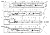
- FIGS. 1a and 1b show a preferred embodiment of an inventive connecting device 1, which serves the construction of a building system 10, as shown in the FIGS. 7b and 8b
- Figure 7a shows a building system 10, which is composed of tubular first system parts 5A, 5B, 5C, 5D and tubular second system parts 3A, 3B, 3C, 3D
- FIG. 8a shows a building system 10, which is composed of plate-shaped first system parts 5A, 5B, 5C, 5D and plate-shaped second system parts 3A, 3B, 3C, 3D.
- tubular or plate-shaped second system parts 3; 3A, 3B, 3C, 3D are the in the FIGS. 1a and 1b integrated connecting devices 1, by means of which two opposing first system parts 5, for example, the system parts 5A and 5B, are connected.
- Connecting device 1 shown has a clamping device 11 with a multipart pull rod, which has a holding head 1111 on one side and a clamping head 1121 on the other side.
- the clamping device 11 has a holding part 111 and a clamping part 112, which are connected to each other by a connecting part 113.
- the holding part 111 is designed as a screw and comprises the holding head 1111 and a threaded holding shaft 1112.
- the clamping part 112 is also designed as a screw and comprises the clamping head 1121 and a threaded clamping shaft 1122.
- the connecting part 113 is a threaded sleeve configured with an internal thread into which the holding part 111 and the clamping part 112 are screwed from both sides such that a desired distance between the holding head 1111 and the chuck 1121 results.
- a lock nut 115 is provided, which is rotated against the connecting sleeve 113, so that the holding shaft 1112 is fixed relative to the connecting sleeve 113.
- the holding shaft 1112, the connecting sleeve 113 and the clamping shaft 1122 form the drawbar.
- a connecting means 114 is applied, which increases the screw-in torque or the unscrewing torque.
- the clamping shaft 1122 can therefore be rotated within the connecting sleeve 113 without being able to detach itself from the connecting sleeve 113 automatically.
- the connecting device 1 is held within a second system part 3, for example a wood-cylindrical or polygonal tubular element or within a wall element, and comprises a first guide part 21, which is arranged adjacent to the holding head 1111, and a second guide part 22, which is arranged adjacent to the clamping head 1121 , By means of the two guide parts 21 and 22, in FIG. 1a Also shown separately, the pull rod 1112, 113, 1121 held displaceable.
- the first guide part 21 has a first hollow cylindrical guide component 211, which is positively inserted into a mounting opening in one of the first system parts 5A, and a second guide component 212, which sits positively in one of the end pieces of the tubular second system part 3.
- the second guide part 22 has a first hollow-cylindrical guide component 221, which is inserted in a form-fitting manner into a mounting opening in the other first system part 5B, and a second guide component 222, which is positively locking sitting in the other end of the tubular second system part 3.
- the first two system parts 5A, 5B and the second system part 3 are positively but loosely connected. By tightening the tensioning device 11, a stable bracing of the first two system parts 5A, 5B with the second system part 3 takes place.
- the holding head 1111 was guided through a mounting opening 51 in one of the first system parts 5A and the clamping head 1121 through a mounting opening 51 in the other first system part 5B. So that the holding head 1111 can no longer get back into the mounting opening 51, a first bearing part 14 has been pushed under the holding head 1111.
- the first bearing part 14 is U-shaped and has a bearing opening 140 which serves to receive the retaining shaft 1112.
- FIG. 1b shown preferably configured second bearing member 15 is pushed, which has a bearing opening 150 which can receive the clamping shaft 1122 and a substantial part of the clamping head 1121.
- the clamping head 1121 is wedge-shaped and aligned such that the legs of the second bearing part 22 can be pushed past it in parallel.
- FIG. 1a is the second bearing part 22 shown in phantom, so that it can be seen that the chuck 1121 is sunk into the second bearing part 22. In this position of the clamping head 1121, the tensioning device 11 or the drawbar 1112, 113, 1122 is not yet tensioned.
- the two first system parts 5A, 5B, in which the two guide parts 21, 22 are used, are held together only loosely.
- the holding head 1111 is pulled by the elastic element or the coil spring 13, which presses against the nut 12, against the first bearing part 14 by the pull rod 1112, 113, 1122 is pressed in the direction of the chuck 1121. In this state, the holding head 1111 therefore already acts with the force of elastic member 13 on the first bearing part 14, while the clamping head 1121 still exerts no force on the second bearing part 22.
- FIG. 1b shows the connecting device 1 of FIG. 1a after the clamping head 1121 has been turned about a quarter turn.
- the clamping head 1121 was rotated via the second bearing part 15, as a result of which the tensioning device 11 was tensioned or the drawbar 1112, 113, 1122 was stretched.
- the holding head 1111 and the clamping head 1112 are pulled with a correspondingly high tensile force against the first and second bearing part 14 and 15 and thus also against the two intermediate first system parts 5A, 5B, which now from both sides to the second system part 3 therebetween press down.
- the two first system parts 5A, 5B and the second system part 3 thus form after turning the clamping head 1121 a stable, but demountable building system 10 in a simple configuration.
- This building system 10 can be expanded as desired.
- the second system element 3 may be configured tubular or plate-shaped.
- FIGS. 2a-2g show in detail the process of installation of the connecting device 1 of FIG. 1a for connecting the two first system parts 5A, 5B, which have a rectangular profile in this embodiment.
- FIG. 2a shows the connecting device 1, which is exemplarily integrated in a plate-shaped second system part 3, before insertion into the first system part 5A.
- the connecting device 1 is guided with the holding head 1111 against the opening 51 in the first system part 5A.
- the holding head 1111 is pressed by the coil spring 13 against the first guide part 21.
- the two bearing parts 21 and 22 are not yet used.
- the second guide part 22 is shown spatially in a sectional view.
- FIG. 2b shows the connecting device 1 of FIG. 2a After the holding head 1111 has been inserted through the mounting hole 51 in the rectangular profile of the first system part 5A. The holding head 1111 is still pressed against the first guide member 21, which is why the first bearing member 14 can not be used yet.
- the connection device 1 in FIG. 2b used in a tubular second system part 3.
- Figure 2d shows the connecting device 1 without external force.
- the pull rod 1112, 113, 1122 is pressed by the coil spring 13 again in the direction of the clamping head 1121, so that the holding head 1111 holds the first bearing part 14 by the force of the coil spring 13.
- the holding head 1111 holds the first bearing part 14 by the force of the coil spring 13.
- FIG. 2e shows the connecting device 1 after the second bearing member 22 was inserted with the corresponding guide component 221 in the mounting hole 51 of the other first system part 5B and the chuck 1121 was passed through this mounting hole 51 therethrough. Also shown is the second bearing part 15, which can be inserted between the clamping head 1121 and the second bearing part 15 in the illustrated orientation of the clamping head 1121.
- FIG. 2f shows the connecting device 1 with the inserted second bearing part 15 before the chuck 1121 is rotated and the tensioning device 11 is tensioned.
- the two first system parts 5A, 5B are thus loosely connected to the second system part 3.
- Figure 2g shows the tensioning device 1 after rotating the chuck 1121 through which the pull rod 1112, 113, 1122 has been stretched and stretched.
- the two first system parts 5A, 5B are thus pulled by the pull rod 1112, 113, 1122 in the manner of a very strong spring against the second system part 3, whereby a stable connection results.
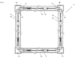
- FIG. 3 Figure 4 shows four first system parts 5A, 5B, 5C, and 5D interconnected by connecting devices 1A, 1B, 1C, and 1D according to the invention held within second system parts 3A, 3B, 3C, and 3D.
- the second system parts 3A, 3B, 3C, and 3D for example, a rectangular box 10 is formed with four walls that connect to the first system parts 5A, 5B, 5C, and 5D, which are designed as rectangular profiles and the metal corner profiles of the box 10th form. If the second system parts 3A, 3B, 3C, and 3D, however, are designed tubular, a pipe system is formed.
- a ring with connectors 1A, 1B, 1C, and 1D is preferably provided at both ends of the first system parts 5A, 5B, 5C, and 5D, so that a building system 10 results in cube shape.
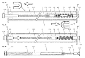
- FIG. 4a shows the connecting device 1 of FIG. 1a
- the coil spring 13 is disposed adjacent to the second guide member 22 and presses against the connecting sleeve 113.
- the pull rod 1112, 113, 1122 is therefore pressed in the direction of the holding head 1111 so that it is lifted from the first guide part 21 and the first bearing part 14 between the holding head 1111 and the first guide member 21 can be used.
- FIG. 4b It is shown that the holding head 1111 is manually pressed against the coil spring 13, so that the chuck 1121 lifts off from the second guide part 22 and the second bearing part 15 can be used.
- This embodiment shows that the person skilled in the kinematic art can realize various equivalent embodiments of the invention.
- Figure 4c shows a preferably configured clamping device 11, which has a holding part 111 with a holding head 1111 and a support shaft 1112 in the form of a threaded sleeve.
- the holding head 1111 is formed by a nut which is rotated on an external thread of the holding shaft 1112.
- the holding shaft 1112 also has an internal thread into which the screw shaft 1122 of the clamping part 112 is screwed.
- the pull rod can be composed of different parts, which can also have different lengths.
- a connection sleeve 113 is dispensed with.
- the use of the nut as a holding head 1111 shows that also threaded rods with a nut instead of the retaining screw 111 and the lag screw 112 of FIG. 4a can be used. Furthermore, a stepped threaded rod or threaded sleeve or a combination thereof may also be used. The said parts are dimensioned such that at a corresponding tensile force results in the desired elongation of the pull rod.
- FIG. 5a shows a preferably ausgestaltetes second bearing part 15, which is insertable into one of the system parts 5A, 5B, 5C, and 5D to the chuck 1121 of Figure 4c to keep.
- this second bearing part 15 is designed to hold the chuck 1121, it can also be used for locking the holding head 1111.
- the second bearing part 22 is U-shaped, fork-shaped or horseshoe-shaped and has a bearing opening 150 which can receive the clamping shaft 1122 of the clamping part 112. Adjacent to the bearing opening 150 is a bearing seat 151 provided with inclined seating surfaces 1511, which are provided parallel to each other on both sides of the bearing opening 150.
- a locking groove 152 Perpendicular to the seats extends a locking groove 152, which serves to hold the clamping head 1121. Furthermore, a coupling element 154, i. provided a bore into which a tool can be introduced to detect the second bearing member 15 to release the clamping member 112 and pull out of the first system part 5.
- FIG. 5b shows the second bearing part 15 with the bearing opening 150, the bearing seat 151 and the locking groove 152 in a sectional view along the in FIG. 5a drawn section line A - A. The cut thus runs centrally through the locking groove 152.
- FIG. 6a shows the clamping part, ie the clamping screw 112 of Figure 4c with the second bearing part 15 of FIG. 5a resting clamping head 1121, which is designed as against the clamping shank 1122 directed wedge 11212 and which rests with the opposing clamping surfaces or wedge walls 11211, which are at least approximately perpendicular to each other, to the seating surfaces 1511 of the bearing seat 151.
- the clamping head 1121 is thus sunk into the bearing seat 151 and can be rotated out of the bearing seat 151 by a rotation, for example, by about 75 ° -85 °.
- the clamping surface 11212 is preferably rounded, so that the clamping surface 11212 and the seat surface 1511 can slide past each other without obstruction.
- the clamping head 1121 also has a coupling element 11210, which is preferably arranged rotated about 85 ° to 90 ° to the wedge 11212 and in which a tool can be positively inserted to grasp the clamping head 1121 and rotate.
- the coupling element 11210 is preferably a slot, but may also be a laterally provided on the clamping head 1121 bore or another form of element and can be adapted to any tools and rotated relative to the wedge 11212th
- FIG. 6a shows that the clamping shaft 1122 is provided with markings M1, M2 and M3, which allow to adjust the distance between the holding head 1111 and the clamping head 1121 corresponding to the present length of the drawbar. This allows a corresponding strain path to be set, which is proportional to the length of the tie rod. After overcoming the strain path should always occur a required tensile force in the tensioning device 11.
- FIG. 6b shows the clamping screw 112 of FIG. 6a after a rotation of not quite 90 °, after the chuck 1121 was rotated out of the bearing seat 151 out.
- the clamping shaft 1122 was stretched accordingly. The stretch is shown symbolically.
- FIG. 6c shows the clamping screw 112 of FIG. 6b after a further rotation of the clamping head 1121, after which the wedge 11212 of the clamping head 1121 was sunk into the locking groove 152 and secured against further rotation.
- Figure 7a shows a building system 30 consisting of tubular first and second system parts 3A, 3B, 3C, 3D and 5A, 5B, 5C, 5D, by inventive connecting devices 1 according to FIG. 1a or FIG. 4a connected to each other.
- FIG. 7b shows a node N of the building system 30 of Figure 7a in an exemplary embodiment with a first system part 5C, which is connected in the region of the node N with three second system parts 3B, 3C and 3E. It is shown that the rectangular profile of the first system part 5C is provided with openings 51 through which a holding head 1111 and two clamping heads 1121 have been inserted into the rectangular profile and are now locked with a first bearing part 14 and two second bearing parts 15 which have been provided , Shown is also a table-shaped cover 500, which can be used frontally in the first system part 5C to complete the node N.
- the bearing parts 14 and 15 have recesses on the back, in which the legs of the table-shaped cover 500 can be inserted.
- FIG. 8a shows an exploded view of a building system 30 consisting of plate-shaped first system parts 5A, 5B, 5C, 5D and plate-shaped second system parts 3A, 3B, 3C, 3D, by inventive connecting devices 1 according to FIG. 1a or FIG. 4a connected to each other. Shown is a plate-shaped system module 50 with integrated therein first system parts 5A, 5B.
- FIG. 8b shows a part of the plate-shaped system module 50 of FIG. 8a , on whose edge two rectangular first system parts 5B are provided. Instead of a continuous first system part 5B, therefore, only parts thereof are provided in the region of the nodes in the system module 50.
- FIG. 8c shows one of the second system parts 3B of FIG. 8a with two therein used in connection devices 1, of which each of the chuck 1121 is visible, which can be locked by means of the second bearing parts 15 shown, after they in the first system parts 5B of FIG. 8b were inserted.
- FIG. 8d shows the second system part 3B in a sectional view along in FIG. 8c drawn section line B - B.
- the system part 3B comprises a cladding 33 consisting of preferably six wall elements, for example made of metal or precious wood, which are connected to one another in a known manner, for example by gluing.
- a cladding 33 consisting of preferably six wall elements, for example made of metal or precious wood, which are connected to one another in a known manner, for example by gluing.
- two structural elements 31 are provided, which give the cladding 33 the required stability and delimit cavities 34 in which the connecting devices 1 are arranged.
- a filling material or insulating material 32 for example cardboard, is provided between the structural elements 31, which gives the second system part 3B the desired properties in terms of strength and insulation.
Abstract
Die Verbindungsvorrichtung (1) umfasst eine Spannvorrichtung (11), die der lösbaren Verbindung von zwei ersten Systemteilen (5A, 5B) eines Bausystems (10) dient, wie eines Möbelstücks, eines Gestells, eines Regals, eines Schranks oder einer Raumabgrenzung. Erfindungsgemäss umfasst die Spannvorrichtung (11) eine einteilige oder mehrteilige Zugstange (1112; 113; 1122), die einen Haltekopf (1111) und einen Spannkopf (1121) miteinander verbindet, der wenigstens eine zur Längsachse der Zugstange (1112; 113; 1122) geneigte Spannfläche (11211) aufweist. Ferner ist ein mit dem einen ersten Systemteil (5A) koppelbares erstes Lagerteil (14) vorgesehen, welches eine der Aufnahme der Zugstange (1112; 113; 1122) dienende Lageröffnung (140) aufweist. Weiter ist ein mit dem anderen ersten Systemteil (5B) koppelbares zweites Lagerteil (15) vorgesehen, welches eine der Aufnahme der Zugstange (1112; 113; 1122) dienende Lageröffnung (150) und einen der Aufnahme des Spannkopfs (1121) dienenden Lagersitz (151) aufweist, aus dem der Spannkopf (1121) mit einer Drehung herausdrehbar ist, um die Zugstange (1112; 113; 1122) zu spannen.The connecting device (1) comprises a tensioning device (11), which serves for the releasable connection of two first system parts (5A, 5B) of a building system (10), such as a piece of furniture, a rack, a shelf, a cupboard or a room delineation. According to the invention, the tensioning device (11) comprises a one-piece or multi-part pull rod (1112; 113; 1122) connecting a holding head (1111) and a chucking head (1121) which is at least one inclined to the longitudinal axis of the drawbar (1112; 113; 1122) Clamping surface (11211) has. Furthermore, a first bearing part (14) which can be coupled to the one first system part (5A) is provided, which has a bearing opening (140) serving to receive the pull rod (1112; 113; 1122). Furthermore, a second bearing part (15) which can be coupled to the other first system part (5B) is provided, which has a bearing opening (150) serving to receive the drawbar (1112; 113; 1122) and a bearing seat (151) serving to receive the clamping head (1121) ), from which the clamping head (1121) is twisted out with a turn to tension the tie rod (1112; 113; 1122).
Description
Die Erfindung betrifft eine Vorrichtung zur lösbaren Verbindung von Elementen eines Bausystems, insbesondere eines Möbelstücks, eines Gestells, eines Regals, eines Schrankes oder einer Raumabgrenzung, sowie ein solches Bausystem.The invention relates to a device for detachable connection of elements of a building system, in particular a piece of furniture, a frame, a shelf, a cabinet or a room delimitation, and such a building system.
Möbelstücke, wie Gestelle, Regale und Schränke, bestehen üblicherweise aus Elementen, die bei der Herstellung durch Schrauben, Nägel, Klebstoff oder mechanische Verbindungsvorrichtungen unlösbar miteinander verbunden werden. Durch den Endabnehmer können diese Gegenstände daher normalerweise nicht selbst zusammengefügt werden, weshalb Bausysteme mit Systemteilen geschaffen wurden, welche vom Endabnehmer anhand von Verbindungsvorrichtungen miteinander verbunden und wieder voneinander gelöst werden können.Furniture, such as racks, shelves and cabinets, usually consist of elements that are permanently connected to each other during manufacture by screws, nails, glue or mechanical fasteners. Therefore, these items can not normally be assembled by the end user themselves, which is why building systems with system parts have been created which can be connected and disconnected from the end user by means of connecting devices.
Aus [1],
Aus [2],
Aus [3],
Aus [4],
Nachteilig bei diesen Verbindungsvorrichtungen ist, dass diese nur in Verbindung mit Rohrelementen einsetzbar sind und deren Verwendung daher limitiert ist. Zur Fixierung der Montageelemente muss zudem auf zwei Seiten eines Rohres in das Rohrsystem eingegriffen werden, wozu Öffnungen oder spezielle Werkzeuge erforderlich sind. Dabei ist sicherzustellen, dass eine stabile kraftschlüssige Verbindung bzw. eine Spannverbindung resultiert und sich diese Verbindung nicht selbsttätig lösen kann. Bei grösserer Krafteinwirkung besteht daher die Gefahr, dass sich eine kraftschlüssige Verbindung lösen kann.A disadvantage of these connecting devices is that they can only be used in conjunction with pipe elements and their use is therefore limited. To fix the mounting elements must also be intervened on two sides of a pipe in the pipe system, including openings or special tools are required. It must be ensured that a stable frictional connection or a clamping connection results and this connection can not solve automatically. With greater force there is therefore the danger that a frictional connection can be solved.
Der vorliegenden Erfindung liegt die Aufgabe zugrunde, eine verbesserte Verbindungsvorrichtung zu schaffen, mittels der beliebige Elemente eines Bausystems, einschliesslich Rohre, miteinander verbindbar sind.The present invention has for its object to provide an improved connection device by means of any elements of a building system, including pipes, are connected to each other.
Insbesondere ist eine Verbindungsvorrichtung zu schaffen, die kostengünstig herstellbar sowie einfach montierbar und wieder demontierbar ist.In particular, a connecting device is to be provided which can be produced cost-effectively and can be easily assembled and disassembled.
Mittels der Verbindungsvorrichtung sollen Systemteile, beispielsweise Teile eines Möbelstücks, eines Gestells, eines Regals, eines Schrankes oder einer Raumabgrenzung, stabil miteinander verbindbar sein, so dass sie sich auch bei grösseren Krafteinwirkungen nicht voneinander lösen.By means of the connecting device system parts, such as parts of a piece of furniture, a frame, a shelf, a cabinet or a space delimitation, stable to be connected to each other, so that they do not dissolve even with large forces.
Die erfindungsgemässe Verbindungsvorrichtung soll universell einsetzbar sein und den einfachen Aufbau beliebiger Bausysteme ermöglichen.The inventive connecting device should be universally applicable and allow the simple construction of any building systems.
Ferner sollen auch unterschiedliche Systemteile, wie Rohre oder Wände, miteinander kombinierbar sein, um ein Bausystem zu schaffen.Furthermore, also different system parts, such as pipes or walls, be combined with each other to create a building system.
Diese Aufgabe wird mit einer Verbindungsvorrichtung gelöst, welche die in Anspruch 1 angegebenen Merkmale aufweist. Vorteilhafte Ausgestaltungen der Erfindung sind in weiteren Ansprüchen angegeben.This object is achieved with a connecting device which has the features specified in
Die Verbindungsvorrichtung umfasst eine Spannvorrichtung, die der lösbaren Verbindung von zwei ersten Systemteilen eines Bausystems dient, wie eines Möbelstücks, eines Gestells, eines Regals, eines Schranks oder einer Raumabgrenzung.The connecting device comprises a tensioning device, which serves for the releasable connection of two first system parts of a building system, such as a piece of furniture, a rack, a shelf, a cupboard or a room delimitation.
Erfindungsgemäss umfasst die Spannvorrichtung eine einteilige oder mehrteilige Zugstange, die einen Haltekopf und einen Spannkopf miteinander verbindet, der wenigstens eine zur Längsachse der Zugstange geneigte Spannfläche aufweist. Ferner ist ein mit dem einen ersten Systemteil koppelbares erstes Lagerteil vorgesehen, welches eine der Aufnahme der Zugstange dienende Lageröffnung aufweist. Weiter ist ein mit dem anderen ersten Systemteil koppelbares zweites Lagerteil vorgesehen, welches eine der Aufnahme der Zugstange dienende Lageröffnung und einen der Aufnahme des Spannkopfs dienenden Lagersitz aufweist, aus dem der Spannkopf mit einer Drehung herausdrehbar ist, um die Zugstange zu spannen.According to the invention, the tensioning device comprises a one-piece or multi-part pull rod, which connects a holding head and a clamping head, which has at least one clamping surface inclined to the longitudinal axis of the pull rod. Furthermore, a first bearing part, which can be coupled to the first system part, is provided, which has a bearing opening serving to receive the drawbar. Further, a second bearing part which can be coupled to the other first system part is provided which has a bearing opening serving to receive the drawbar and a bearing seat serving to receive the clamping head, from which the clamping head can be turned out with a turn in order to tension the drawbar.
Der Erfindung liegt der Gedanke zu Grunde, dass eine metallene Zugstange federelastisch dehnbar ist und dass zwei erste Systemteile durch eine gespannte Zugstange formschlüssig stabil miteinander verbindbar und gegen ein dazwischen liegendes Distanzelement, bzw. ein nachstehend beschriebenes zweites Systemteil, anziehbar sind. Dazu werden der Haltekopf und der Spannkopf je durch eine Montageöffnung im zugehörigen ersten Systemteil hindurchgeführt und auf der anderen Seite anhand eines zugehörigen Lagerteils fixiert. Die beiden Systemteile sind nun formschlüssig miteinander verbunden. Der keilförmig ausgestaltete Spannkopf ist in den Lagersitz des zweiten Lagerteils eingesenkt und kann nun typischerweise durch eine Vierteldrehung aus dem Lagersitz heraus gedreht werden, so dass er oberhalb des Lagersitzes auf dem zweiten Lagerteil ruht. Die Zugstange wurde nun um die Distanz gedehnt, um die der Spannkopf aus dem Lagersitz heraus geführt und angehoben wurde.The invention is based on the idea that a metal tie rod is elastically extensible and that two first system parts by a tensioned tie rod form-fitting stable connected to each other and against an intermediate spacer element, or a below-described second system part, are attractible. For this purpose, the holding head and the clamping head are each passed through a mounting opening in the associated first system part and fixed on the other side by means of an associated bearing part. The two system parts are now positively connected with each other. The wedge-shaped designed clamping head is sunk into the bearing seat of the second bearing part and can now be typically rotated by a quarter turn out of the bearing seat so that it rests above the bearing seat on the second bearing part. The drawbar was then stretched by the distance by which the chuck head was guided out of the bearing seat and raised.
Die Montage erfolgt mit wenigen Handgriffen, mit denen die Verbindungsvorrichtung in die beiden ersten Systemteile eingesetzt und durch eine Vierteldrehung des Spannkopfs gespannt wird. Die Vierteldrehung kann schnell und bequem vollzogen werden, so dass das Spannen nur wenige Sekunden in Anspruch nimmt. Die dadurch in der Zugstange resultierende Zugkraft bewirkt, dass die Verbindungsvorrichtung die beiden ersten Systemteile gegeneinander bzw. gegen ein Distanzelement zieht und spielfrei hält.The assembly is done with a few simple steps, with which the connecting device is inserted into the first two system parts and stretched by a quarter turn of the clamping head. The quarter turn can be done quickly and easily, so that the clamping takes only a few seconds. The resulting tensile force in the pull rod causes the connecting device pulls the two first system parts against each other or against a spacer element and holds free of play.
Damit die Drehung des Spannkopfs innerhalb des Lagersitzes leicht vollzogen werden kann, weist dieser vorzugsweise wenigstens eine zur Längsachse der Zugstange geneigte Sitzfläche auf, die vorzugsweise parallel zur Spannfläche des Spannkopfs verläuft, wenn dieser im Lagersitz eingesenkt ist. Die Spannfläche und die Sitzfläche sind vorzugsweise derart ausgestaltet, dass der Kontakt zwischen der Spannfläche und der Sitzfläche stets flächig und ohne Einwirkung einer Kante ist. Die am Spannkopf vorgesehene Spannfläche kann entlang einer Bahn verlaufen, die stets parallel an der Sitzfläche anliegt. Beispielsweise verläuft die Bahn entsprechend einer Gewindeflanke mit entsprechender Gewindehöhe, die zumindest annähernd der Höhe des Spannkopfs oder einem Teil davon entspricht. Durch die gegenseitige flächige Kontaktierung der Spannfläche und der Sitzfläche wird gewährleistet, dass die Drehung mit minimalem Kraftaufwand vollzogen werden kann und ein Verschleiss der kontaktierenden Elemente vermieden wird. Der Drehbereich des Spannkopfs liegt innerhalb des Bereichs einer Umdrehung, wobei die minimale Drehung und die maximale Steigung von den gewünschten Zugkräften und den verwendeten Materialien abhängig sind. Idealerweise wird für das Spannen der Spannvorrichtung eine Drehung von 75° bis 90°, idealerweise 85° vorgesehen.Thus, the rotation of the clamping head can be easily performed within the bearing seat, this preferably has at least one inclined to the longitudinal axis of the tie rod seating surface, which is preferably parallel to the clamping surface of the clamping head when it is sunk in the bearing seat. The clamping surface and the seat surface are preferably designed such that the contact between the clamping surface and the seat surface is always flat and without the action of an edge. The clamping surface provided on the clamping head can run along a path which always rests parallel to the seat surface. For example, the web runs according to one Thread flank with appropriate thread height, which corresponds at least approximately to the height of the chuck or a part thereof. Due to the mutual surface contact of the clamping surface and the seat ensures that the rotation can be performed with minimal effort and wear of the contacting elements is avoided. The range of rotation of the chuck is within the range of one revolution, with minimum rotation and maximum slope depending on the desired tensile forces and the materials used. Ideally, a tension of 75 ° to 90 °, ideally 85 ° is provided for the clamping of the tensioning device.
Der Spannkopf und der Lagersitz können auf einer Seite oder auf beiden Seiten mit geneigten Flächen versehen sein. Der Spannkopf weist beispielsweise die Form eines Keils auf, dessen Keilflächen die Spannflächen bilden. Eine sehr gute Kontaktierung wird erzielt, wenn die Keilflächen bzw. die Spannflächen peripher nicht zu einer Kante, sondern zu einer Abrundung verlaufen. Bei dieser Ausgestaltung der Sitzflächen und der Spannflächen muss bei der Drehung des Spannkopfs somit nebst geringen Reibungskräften im Wesentlichen nur die Zugkraft der Zugstange überwunden werden, um den Spannkopf auf die Oberseite des Lagerteils zu fahren.The clamping head and the bearing seat can be provided on one side or on both sides with inclined surfaces. The clamping head has, for example, the shape of a wedge whose wedge surfaces form the clamping surfaces. A very good contact is achieved when the wedge surfaces or the clamping surfaces are not peripheral to an edge, but to a rounding. In this embodiment of the seat surfaces and the clamping surfaces, therefore, in addition to low frictional forces, essentially only the tensile force of the drawbar must be overcome during the rotation of the clamping head in order to drive the clamping head onto the upper side of the bearing part.
Damit der Spannkopf auf der Oberseite des Lagerteils sicher gehalten wird, ist dort vorzugsweise eine Arretiernut vorgesehen, in die der vorzugsweise keilförmige Spannkopf einrasten kann. Die Tiefe der Arretiernut kann dabei sehr gering, beispielsweise weniger als 1/10 mm sein, wird vorzugsweise jedoch in einem Bereich von etwa 3/10mm gewählt. Aufgrund der Zugkraft der Zugstange wird der Spannkopf stabil in der Arretiernut gehalten. Sofern die Arretiernut keilförmig ausgebildet ist, kann der Spannkopf auch leicht wieder aus der Arretiernut heraus gedreht werden.Thus, the clamping head is securely held on top of the bearing part, there is preferably provided a locking groove into which the preferably wedge-shaped clamping head can engage. The depth of the locking groove can be very small, for example, less than 1/10 mm, but is preferably selected in a range of about 3 / 10mm. Due to the tensile force of the pull rod of the clamping head is held stable in the locking groove. If the locking groove wedge-shaped is formed, the clamping head can also be easily rotated out of the locking groove out.
Die Drehung des Spannkopfs aus dem Lagersitz entspricht vorzugsweise einer Drehung von 85°-90°, so dass die vorzugsweise keilförmige Öffnung des Lagersitzes und die Arretiernut vorzugsweise senkrecht zueinander ausgerichtet sind.The rotation of the clamping head from the bearing seat preferably corresponds to a rotation of 85 ° -90 °, so that the preferably wedge-shaped opening of the bearing seat and the locking groove are preferably aligned perpendicular to each other.
Die beiden Lagerteile, mittels denen der Haltekopf und der Spannkopf innerhalb der zugehörigen Systemteile gehalten werden, sind vorzugsweise U-förmig ausgestaltet, so dass sie von der Seite her unter den Haltekopf oder den Spannkopf geschoben werden können, der sich danach nicht wieder vom zugehörigen ersten Systemteil lösen kann. Vorzugsweise weist jedes Systemteil eine Montageöffnung auf, durch die der Haltekopf oder der Spannkopf hineingeschoben werden kann. Durch das entsprechende erste oder zweite Lagerteil, welches grösser ist als die Montageöffnung, wird der Haltekopf oder der Spannkopf in der Art einer Unterlagscheibe gehalten.The two bearing parts, by means of which the holding head and the clamping head are held within the associated system parts, are preferably designed U-shaped, so that they can be pushed from the side under the holding head or the clamping head, which then does not return from the associated first System part can solve. Preferably, each system part has a mounting opening through which the holding head or the clamping head can be pushed. By the corresponding first or second bearing part, which is larger than the mounting opening, the holding head or the clamping head is held in the manner of a washer.
Die ersten Systemteile weisen z.B. ein Rechteckprofil auf, welches in einem Knotenpunkt vorzugsweise mehrere Montageöffnungen aufweist. In einem Knotenpunkt des im Aufbau begriffenen Bausystems können daher die Halteköpfe oder die Spannköpfe von mehreren Verbindungsvorrichtungen aus mehreren Richtungen in ein erstes Systemteil eingeführt werden. Zugriff erhält der Anwender beispielsweise von der Stirnseite des ersten Systemteils, an der eine Öffnung vorgesehen ist, durch die hindurch die Lagerteil eingesetzt werden (siehe z.B.
Die Zugstange kann verschiedenartig ausgestaltet sein und ist vorzugsweise verlängerbar, so dass die Verbindungsvorrichtung leicht an die Dimensionen des Bausystems und der Systemteile angepasst werden kann.The pull rod can be designed in various ways and is preferably extendable, so that the connecting device easily adapted to the dimensions of the building system and system parts.
Vorzugsweise umfasst die Zugstange ein mit dem Haltekopf versehenes Halteteil, vorzugsweise eine Halteschraube, und ein mit dem Spannkopf versehenes Spannteil, vorzugsweise eine Spannschraube, die direkt oder durch ein Verbindungsteil, vorzugsweise eine Gewindehülse, miteinander verbunden sind. Die Gewindehülse erlaubt es, das Halteteil und das Spannteil gegeneinander oder auseinander zu drehen, um den Abstand zwischen dem Haltekopf und dem Spannkopf einzustellen.Preferably, the pull rod comprises a holding part provided with the holding head, preferably a holding screw, and a clamping part provided with the clamping head, preferably a clamping screw, which are connected to each other directly or by a connecting part, preferably a threaded sleeve. The threaded sleeve makes it possible to rotate the holding part and the clamping part against each other or apart to adjust the distance between the holding head and the clamping head.
Es ist auch möglich, das Halteteil und das Spannteil derart auszubilden, dass diese gegeneinander verschiebbar und direkt miteinander verbindbar sind. Beispielsweise sind das Halteteil und das Spannteil durch Gewindeelemente miteinander verbunden und gegeneinander drehbar. Beispielsweise ist eines der beiden Teile als Gewindehülse und das andere Teil als Gewindestange ausgebildet. Alternativ können das Halteteil und das Spannteil mit Kopplungselementen, wie Haken und Öffnungen, versehen sein, die es erlauben, das Halteteil und das Spannteil mit gewähltem Abstand zwischen Haltekopf und Spannkopf miteinander zu verbinden.It is also possible to form the holding part and the clamping part such that they are mutually displaceable and directly connectable. For example, the holding part and the clamping part are connected to each other by threaded elements and against each other rotatable. For example, one of the two parts is designed as a threaded sleeve and the other part as a threaded rod. Alternatively, the holding part and the clamping part may be provided with coupling elements, such as hooks and openings, which allow to connect the holding part and the clamping part with a selected distance between the holding head and the clamping head.
Der Abstand zwischen dem Haltekopf und dem Spannkopf wird vorzugsweise unter Berücksichtigung der Länge der Zugstange gewählt.The distance between the holding head and the clamping head is preferably selected taking into account the length of the drawbar.
Der Abstand zwischen Haltekopf und Spannkopf bei entspannter Zugstange und die resultierende Längendehnung nach dem Drehen des Spannkopfs entsprechen zusammen der Gesamtlänge der gespannten Zugstange. Die Längendehnung, die erforderlich ist, um eine gewünschte Zugkraft in der Zugstange zu erreichen, ist proportional zur Länge der Zugstange selbst. Bei längeren Zugstangen ist daher eine entsprechend grössere Längendehnung erforderlich. Entsprechend ist auch die Höhe des Spannkopfs bzw. die Länge der Spannfläche zu wählen.The distance between the holding head and clamping head with a relaxed drawbar and the resulting elongation after rotation of the clamping head together correspond to the total length of the tensioned tie rod. The elongation required to achieve a desired tensile force in the tie rod is proportional to the length of the tie rod itself. For longer tie rods, therefore, a correspondingly greater elongation is required required. Accordingly, the height of the clamping head or the length of the clamping surface is to be selected.
Vorzugsweise wird die Zugstange mit wenigstens einer Markierung versehen, die dem Anwender die erforderliche Einstellung der Länge der Zugstange anzeigt. Beispielsweise wird das Spannteil in die Verbindungshülse eingeschraubt, bis die Markierung erreicht ist.Preferably, the drawbar is provided with at least one mark indicating to the user the required adjustment of the length of the drawbar. For example, the clamping part is screwed into the connecting sleeve until the marking is reached.
Vorzugsweise wird das Halteteil oder das Spannteil beispielsweise drehfest mit der Verbindungshülse verbunden, während das Spannteil oder das Halteteil mit einem Gewindeschaft innerhalb der Verbindungshülse drehbar ist. Damit sich die gewählte Einstellung nicht selbsttätig verändert, wird innerhalb der Gewindehülse vorzugsweise eine zähflüssige Gewindebeschichtung vorgesehen, welche die gegeneinander drehbaren Gewindeteile kraftschlüssig miteinander verbindet und eine gegenseitige Drehung der beiden Gewindeteile nur unter Einwirkung eines entsprechend hohen Drehmoments erlaubt.Preferably, the holding part or the clamping part, for example, rotatably connected to the connecting sleeve, while the clamping part or the holding part is rotatable with a threaded shaft within the connecting sleeve. Thus, the selected setting does not change automatically, preferably a viscous threaded coating is provided within the threaded sleeve, which connects the mutually rotatable threaded parts frictionally together and allows a mutual rotation of the two threaded parts only under the action of a correspondingly high torque.
In bevorzugten Ausgestaltungen ist die Verbindungsvorrichtung in ein zweites Systemteil, vorzugsweise ein Rohrelement oder ein Wandelement, eingebettet, welches ein Distanzelement bildet, gegen das die beiden ersten Systemteile anziehbar sind. Möglich ist jedoch auch die Verwendung eines separaten Distanzelements.In preferred embodiments, the connecting device is embedded in a second system part, preferably a tubular element or a wall element, which forms a spacer element against which the first two system parts can be tightened. However, it is also possible to use a separate spacer element.
Sofern das zweite Systemteil als Wandelement ausgebildet ist, so sind zwei Verbindungsvorrichtungen parallel zueinander ausgerichtet an den Seiten des Wandelements vorgesehen. Die beiden ersten Systemteile, beispielsweise ebenfalls Wandelemente werden daher durch ein weiteres Wandelement bzw. die darin integrierten Verbindungsvorrichtungen miteinander verbunden. Alternativ können Bausysteme mit Rohren aufgebaut werden, die beispielsweise transparente Platten halten. Weiterhin kann vorteilhaft ein Bausystem errichtet werden, welches Rohrelemente und Wandelemente umfasst, so dass ein offenes Raumteil, beispielsweise eine Bücherablage, mit einem geschlossenen Raumteil, beispielsweise einem Schrank, in einem einzigen Bausystem kombiniert werden kann.If the second system part is designed as a wall element, then two connecting devices are provided aligned parallel to one another on the sides of the wall element. The two first system parts, for example, wall elements are therefore connected to each other by another wall element or the integrated therein connecting devices. Alternatively, building systems can be constructed with pipes which, for example, hold transparent plates. Furthermore, advantageously, a building system can be constructed, which comprises pipe elements and wall elements, so that an open space part, such as a bookcase, with a closed space part, such as a cabinet, can be combined in a single building system.
Bei der Integration der Verbindungsvorrichtung in ein zweites Systemteil wird vorzugsweise vorgesehen, dass die Zugstange entlang einer gewählten Achse verschiebbar gehalten ist. Dazu werden innerhalb des zweiten Systemteils Führungsteile vorgesehen, die je eine Führungsöffnung aufweisen, innerhalb denen die Zugstange axial verschiebbar gelagert ist. Sofern die Führungsteile innerhalb von rohrförmigen zweiten Systemteilen angeordnet werden, so werden vorzugsweise zylinderförmige Führungsteile verwendet, deren Aussendurchmesser dem Innendurchmesser der Rohrelemente entspricht.In the integration of the connecting device in a second system part is preferably provided that the pull rod is slidably held along a selected axis. For this purpose, guide parts are provided within the second system part, each having a guide opening, within which the pull rod is mounted axially displaceable. If the guide parts are arranged within tubular second system parts, it is preferable to use cylindrical guide parts whose outside diameter corresponds to the inside diameter of the tube elements.
Damit bei der Verbindung der ersten und zweiten Systemteile sofort eine korrekte gegenseitige Positionierung erzielt wird, werden vorzugsweise zweiteilige Führungsteile verwendet, die eine formschlüssig in das erste Systemteil einsetzbare erste Führungskomponente und eine vorzugsweise formschlüssig in das zweite Systemteil einsetzbare zweite Führungskomponente aufweisen. Vorzugsweise sind die beiden Führungskomponenten als Ringflanschelemente oder als Flanschzapfen ausgebildet.In order to ensure correct mutual positioning during the connection of the first and second system parts, two-part guide parts are preferably used which have a first guide component which can be positively inserted into the first system part and a second guide component which can preferably be inserted in a form-fitting manner into the second system part. Preferably, the two guide components are designed as annular flange elements or as a flange pin.
In weiteren bevorzugten Ausgestaltungen umfasst die Verbindungsvorrichtung ein elastisches Element, wie eine Schraubenfeder oder Spiralfeder, das auf eines der Führungsteile abgestützt ist und auf die Zugstange einwirkt, so dass diese in Richtung des anderen Führungsteils gedrückt wird. Beispielsweise umfasst die Zugstange einen Gewindeschaft, auf dem eine Schraubenmutter sitzt, gegen die das elastische Element andrückt. Damit das Lagerteil eingesetzt oder entfernt werden kann, wird die Zugstange manuell gegen das elastische Element verschoben, so dass der Haltekopf oder der Spannkopf angehoben wird und das Lagerteil eingesetzt oder entnommen werden kann. Anschliessend wird die Zugstange vom elastischen Element wieder axial verschoben, bis der im Bereich des elastischen Elements liegende Haltekopf oder Spannkopf am eingesetzten Lagerteil anliegt und gehalten wird. Anschliessend wird ein weiteres erstes Systemteil auf der anderen Seite der Zugstange angeordnet und durch eine Drehung des Spannkopfs fixiert. Die Montage der Verbindungsvorrichtung erfolgt daher schrittweise unterstützt von dem als Druckfeder agierenden elastischen Element. Der Aufbau einfacher und komplexer Bausysteme mit beliebigen Systemteilen kann daher rasch und bequem vollzogen werden.In further preferred embodiments, the connecting device comprises an elastic element, such as a helical spring or spiral spring, which is supported on one of the guide parts and acts on the pull rod, so that it is pressed in the direction of the other guide part. For example, the pull rod comprises a threaded shaft on which a nut sits against the presses the elastic element. So that the bearing part can be used or removed, the pull rod is manually displaced against the elastic element, so that the holding head or the clamping head is raised and the bearing part can be inserted or removed. Subsequently, the pull rod is again axially displaced by the elastic element until the lying in the region of the elastic element holding head or clamping head rests on the bearing part used and is held. Subsequently, a further first system part is arranged on the other side of the pull rod and fixed by a rotation of the clamping head. The assembly of the connecting device is therefore progressively supported by the acting as a compression spring elastic element. The construction of simple and complex construction systems with any system parts can therefore be completed quickly and conveniently.
Nachfolgend wird die Erfindung anhand von Zeichnungen näher erläutert. Dabei zeigt:
- Fig. 1a
- eine dem Aufbau eines Bausystems dienende erfindungsgemässe Verbindungsvorrichtung 1 mit einer noch nicht festgezogen Spannvorrichtung 11, mittels der zwei erste
Systemteile - Fig. 1b
- die
Verbindungsvorrichtung 1 vonFigur 1a nach demFestziehen der Spannvorrichtung 11; - Fig. 2a - 2g
- den Vorgang der
Installation der Verbindungsvorrichtung 1 vonFigur 1a zur Verbindung der zwei erstenSystemteile - Fig. 3
- vier erste
Systemteile Verbindungsvorrichtungen und 1D miteinander verbunden sind, die innerhalbvon zweiten Systemteilen und 3D gehalten sind; - Fig. 4a
- die
Verbindungsvorrichtung 1 vonFigur 1a in einer weiteren vorzugsweisen Ausgestaltung mit der noch nicht festgezogenen Spannvorrichtung 11; - Fig. 4b
- die
Verbindungsvorrichtung 1 vonFigur 4a nachdem dieSpannvorrichtung 11 inRichtung zum Spannkopf 1121 verschoben und dieser vom Führungsteil 22 abgehoben wurde,um das Lagerteil 15 einsetzen zu können; - Fig. 4c
- eine vorzugsweise ausgestaltete Spannvorrichtung 11, die
ein Halteteil 111mit einem Haltekopf 1111 und einem Halteschaft 1112 in Form einer Gewindehülse umfasst, die ein Aussengewinde und Innengewinde aufweist, indem ein Spannschaft 1122eines Spannteils 112 gehalten ist; - Fig. 5a
ein zweites Lagerteil 15, welches in eines derSystemteile und 5D einsetzbar ist, um einen Spannkopf 1121 zu halten;- Fig. 5b
das zweite Lagerteil 15mit der Lageröffnung 150,dem Lagersitz 151 und der Arretiernut 152 in Schnittdarstellung entlang der inFigur 5a eingezeichneten Schnittlinie A--A;- Fig. 6a
- die
Spannschraube 112 vonFigur 4c mit dem im zweiten Lagerteil 15 vonFigur 5a ruhenden Spannkopf 1121, der als gegenden Spannschaft 1122gerichteter Keil 11212 ausgebildet ist und der mit den einander gegenüberliegenden Spannflächen bzw. Keilwänden 11211 anden Sitzflächen 1511 desLagersitzes 151 anliegt; - Fig. 6b
- die
Spannschraube 112 vonFigur 6a nach einer Drehung von zum Beispiel 85°, nach der der Spannkopf 1121aus dem Lagersitz 151 hinaus gedreht wurde; - Fig. 6c
- die
Spannschraube 112 vonFigur 6b nach einer weiteren Drehung des Spannkopfs 1121 um z.B. 5°, nach der derKeil 11212 des Spannkopfs 1121 indie Arretiernut 152 eingesenkt wurde; - Fig. 7a
- ein Bausystem 30 bestehend aus rohrförmigen ersten
Systemteilen Figur 1a oderFigur 4a zusammengehalten werden; - Fig. 7b
- einen Knotenpunkt N des Bausystems 30 von
Figur 7a in beispielsweiser Ausgestaltung; - Fig. 8a
- in Explosionsdarstellung ein Bausystem 30 bestehend aus plattenförmigen ersten
Systemteilen Systemteilen Figur 1a oderFigur 4a zusammengehalten werden; - Fig. 8b
- einen Teil eines plattenförmigen Systemmoduls 50 mit darin
integrierten ersten Systemteilen - Fig. 8c
- eines der zweiten
Systemteile 3B vonFigur 8a mit zwei darin eingesetzten erfindungsgemässen Verbindungsvorrichtungen 1, von denen je der Spannkopf 1121und das Führungsteil 22 sichtbar sind, zu deren Arretierung zwei Montageteile 15 bereitgestellt wurden; und - Fig. 8d
das zweite Systemteil 3B in einer Schnittdarstellung entlang der inFigur 8c eingezeichneten Schnittlinie B--B.
- Fig. 1a
- a connecting
device 1 according to the invention which serves the construction of a building system with aclamping device 11 which has not yet been tightened, by means of which twofirst system parts - Fig. 1b
- the connecting
device 1 ofFIG. 1a after tightening theclamping device 11; - Fig. 2a - 2g
- the process of installation of the connecting
device 1 ofFIG. 1a for connecting the twofirst system parts - Fig. 3
- four
first system parts devices second system parts - Fig. 4a
- the connecting
device 1 ofFIG. 1a in a further preferred embodiment with the not yet tightenedclamping device 11; - Fig. 4b
- the connecting
device 1 ofFIG. 4a after thetensioning device 11 has been moved in the direction of theclamping head 1121 and this has been lifted from theguide member 22 to use the bearingmember 15 can; - Fig. 4c
- a preferably configured clamping
device 11, which comprises a holdingpart 111 with a holdinghead 1111 and a holdingshaft 1112 in the form of a threaded sleeve having an external thread and internal thread, in which aclamping shaft 1122 of a clampingmember 112 is held; - Fig. 5a
- a
second bearing part 15 which is insertable into one of thesystem parts chuck 1121; - Fig. 5b
- the
second bearing part 15 with thebearing opening 150, the bearingseat 151 and the lockinggroove 152 in a sectional view along the inFIG. 5a drawn section line A - A; - Fig. 6a
- the clamping
screw 112 ofFigure 4c with thesecond bearing part 15 ofFIG. 5a restingclamping head 1121, which is designed as against the clampingshaft 1122 directedwedge 11212 and with the opposite Clamping surfaces or wedge walls 11211 rests against the seat surfaces 1511 of thebearing seat 151; - Fig. 6b
- the clamping
screw 112 ofFIG. 6a after a rotation of, for example, 85 °, after which thechuck 1121 has been rotated out of thebearing seat 151; - Fig. 6c
- the clamping
screw 112 ofFIG. 6b after a further rotation of theclamping head 1121 by, for example, 5 °, after which thewedge 11212 of theclamping head 1121 has been sunk into the lockinggroove 152; - Fig. 7a
- a building system 30 consisting of tubular
first system parts devices 1 according toFIG. 1a orFIG. 4a held together; - Fig. 7b
- a node N of the building system 30 of
Figure 7a in an exemplary embodiment; - Fig. 8a
- an exploded view of a building system 30 consisting of plate-shaped
first system parts second system parts devices 1 according toFIG. 1a orFIG. 4a held together; - Fig. 8b
- a portion of a plate-shaped
system module 50 having integrated thereinfirst system parts - Fig. 8c
- one of the
second system parts 3B ofFIG. 8a with two therein used connectingdevices 1, of which each of theclamping head 1121 and theguide member 22 visible are, for their locking two mountingparts 15 were provided; and - Fig. 8d
- the
second system part 3B in a sectional view along inFIG. 8c drawn section line B - B.
Die
In die rohrförmigen oder plattenförmigen zweiten Systemteile 3; 3A, 3B, 3C, 3D sind die in den
Die in
Auf dem Teil des Spannschafts 1122, der in die Verbindungshülse 113 eingedreht ist, ist ein Verbindungsmittel 114 aufgebracht, welches das Einschraubdrehmoment oder das Ausschraubdrehmoment erhöht. Der Spannschaft 1122 kann daher innerhalb der Verbindungshülse 113 gedreht werden, ohne dass er sich selbsttätig aus der Verbindungshülse 113 lösen kann.On the part of the
Die Verbindungsvorrichtung 1 ist innerhalb eines zweiten Systemteiles 3, beispielsweise eines holzzylindrischen oder mehrkantigen Rohrelements oder innerhalb eines Wandelements, gehalten und umfasst ein erstes Führungsteil 21, das benachbart zum Haltekopf 1111 angeordnet ist, und ein zweites Führungsteil 22, das benachbart zum Spannkopf 1121 angeordnet ist. Mittels der beiden Führungsteile 21 und 22, die in
Das erste Führungsteil 21 weist eine erste hohlzylindrische Führungskomponente 211, die formschlüssig in eine Montageöffnung in einem der ersten Systemteile 5A eingesetzt ist, und eine zweite Führungskomponente 212 auf, die formschlüssig in einem der Endstücke des rohrförmigen zweiten Systemteils 3 sitzt.The
Das zweite Führungsteil 22 weist eine erste hohlzylindrische Führungskomponente 221, die formschlüssig in eine Montageöffnung im anderen ersten Systemteil 5B eingesetzt ist, und eine zweite Führungskomponente 222 auf, die formschlüssig im anderen Endstück des rohrförmigen zweiten Systemteils 3 sitzt.The
Die beiden ersten Systemteile 5A, 5B und das zweite Systemteil 3 sind formschlüssig aber lose miteinander verbunden. Durch das Anziehen der Spannvorrichtung 11 erfolgt ein stabiles Verspannen der beiden ersten Systemteile 5A, 5B mit dem zweiten Systemteil 3.The first two
Dazu wurde der Haltekopf 1111 durch eine Montageöffnung 51 in einem der ersten Systemteile 5A und der Spannkopf 1121 durch eine Montageöffnung 51 im anderen ersten Systemteil 5B hindurch geführt. Damit der Haltekopf 1111 nicht mehr zurück in die Montageöffnung 51 gelangen kann, wurde ein erstes Lagerteil 14 unter den Haltekopf 1111 geschoben. Das erste Lagerteil 14 ist U-förmig ausgebildet und weist eine Lageröffnung 140 auf, die der Aufnahme des Halteschafts 1112 dient.For this purpose, the holding
Unter den Spannkopf 1121 wird das in
Die
In
Ein Ring mit Verbindungsvorrichtungen 1A, 1B, 1C, und 1D ist vorzugsweise an beiden Enden der ersten Systemteile 5A, 5B, 5C, und 5D vorgesehen, so dass ein Bausystem 10 in Würfelform resultiert.A ring with
In
Das zweite Lagerteil 22 ist U-förmig, Gabel-förmig oder Hufeisen-förmig ausgestaltet und weist eine Lageröffnung 150 auf, die den Spannschaft 1122 des Spannteils 112 aufnehmen kann. Angrenzend an die Lageröffnung 150 ist ein Lagersitz 151 mit geneigten Sitzflächen 1511 vorgesehen, welche parallel zueinander beidseits der Lageröffnung 150 vorgesehen sind.The
Senkrecht zu den Sitzflächen verläuft eine Arretiernut 152, die dem Halten des Spannkopfs 1121 dient. Weiterhin ist ein Kopplungselement 154, d.h. eine Bohrung vorgesehen, in die ein Werkzeug eingeführt werden kann, um das zweite Lagerteil 15 zu erfassen, vom Spannteil 112 zu lösen und aus dem ersten Systemteil 5 heraus zu ziehen.Perpendicular to the seats extends a locking
-
[1]
EP0400345A1 EP0400345A1 -
[2]
DE4316808A1 DE4316808A1 -
[3]
WO02/099292A1 WO02 / 099292A1 -
[4]
EP2034194B1 EP2034194B1
- 11
- Verbindungsvorrichtungconnecting device
- 1010
- Bausystem, wie Möbel, Regal, Gestell, oder RaumabgrenzungBuilding system, such as furniture, shelf, rack, or room delimitation
- 1111
- Spannvorrichtungjig
- 111111
- Halteteil, HalteschraubeHolding part, retaining screw
- 11111111
- Haltekopfholding head
- 11121112
- Halteschaftholding shaft
- 112112
- Spannteiltensioning part
- 11211121
- Spannkopfclamping head
- 1121011210
- Kopplungselementcoupling element
- 1121111211
- Spannflächeclamping surface
- 1121211212
- Keilwedge
- 113113
- Verbindungsteil, VerbindungshülseConnecting part, connecting sleeve
- 114114
- Gewindebeschichtung, VerbindungsmaterialThread coating, connecting material
- 115115
- Kontermutterlocknut
- 1313
- elastisches Element, Federelastic element, spring
- 1414
- erstes Lagerteilfirst bearing part
- 140140
- Lageröffnungbearing opening
- 1515
- zweites Lagerteilsecond bearing part
- 150150
- Lageröffnungbearing opening
- 151151
- Lagersitzbearing seat
- 15111511
- Sitzflächeseat
- 152152
- Arretiernutlocking groove
- 154154
- Kopplungselementcoupling element
- 155155
- Ausnehmungenrecesses
- 2121
- erstes Führungsteilfirst guide part
- 211211
- erste Führungskomponentefirst management component
- 212212
- zweite Führungskomponentesecond guiding component
- 2222
- zweites Führungsteilesecond guide parts
- 221221
- erste Führungskomponentefirst management component
- 222222
- zweite Führungskomponentesecond guiding component
- 33
- zweites Systemteilsecond part of the system
- 3A, ..., 3D3A, ..., 3D
- zweite Systemteilesecond system parts
- 3131
- Strukturelementestructural elements
- 3232
- Füllmaterialfilling material
- 3333
- Verkleidungpaneling
- 3434
- Hohlräumecavities
- 5a, ..., 5D5a, ..., 5D
- erste Systemteilefirst system parts
- 5050
- Systemmodulsystem module
- 500500
- Abdeckungcover
- 51, 5251, 52
- Montageöffnungmounting hole
Claims (15)
Priority Applications (1)
| Application Number | Priority Date | Filing Date | Title |
|---|---|---|---|
| EP20130190410 EP2865902A1 (en) | 2013-10-28 | 2013-10-28 | Connecting device for a construction system and construction system |
Applications Claiming Priority (1)
| Application Number | Priority Date | Filing Date | Title |
|---|---|---|---|
| EP20130190410 EP2865902A1 (en) | 2013-10-28 | 2013-10-28 | Connecting device for a construction system and construction system |
Publications (1)
| Publication Number | Publication Date |
|---|---|
| EP2865902A1 true EP2865902A1 (en) | 2015-04-29 |
Family
ID=49513755
Family Applications (1)
| Application Number | Title | Priority Date | Filing Date |
|---|---|---|---|
| EP20130190410 Withdrawn EP2865902A1 (en) | 2013-10-28 | 2013-10-28 | Connecting device for a construction system and construction system |
Country Status (1)
| Country | Link |
|---|---|
| EP (1) | EP2865902A1 (en) |
Cited By (4)
| Publication number | Priority date | Publication date | Assignee | Title |
|---|---|---|---|---|
| US9764864B1 (en) * | 2012-10-26 | 2017-09-19 | Change Parts, Inc. | Transgrip arm assembly with quick change connection |
| DE102020116908A1 (en) | 2020-06-26 | 2021-12-30 | InnoDo AG | Clamping unit as well as transport and / or storage unit |
| DE102022107208B3 (en) | 2021-12-20 | 2023-06-01 | InnoDo AG | Clamping unit and storage unit with at least one clamping unit |
| EP4201831A1 (en) | 2021-12-20 | 2023-06-28 | InnoDo AG | Clamping unit and storage unit with at least one clamping unit |
Citations (7)
| Publication number | Priority date | Publication date | Assignee | Title |
|---|---|---|---|---|
| FR719061A (en) * | 1931-06-24 | 1932-02-01 | One-touch bolt for upholstery and other applications | |
| FR2530703A1 (en) * | 1982-05-03 | 1984-01-27 | Germain Esteban | Connection device between post and crosspieces. |
| EP0400345A1 (en) | 1989-05-30 | 1990-12-05 | Usm U. Schaerer Soehne Ag | Fixing element |
| WO1994024441A1 (en) * | 1993-04-19 | 1994-10-27 | Henning Lykke Jensen | A connection between furniture legs |
| DE4316808A1 (en) | 1993-05-19 | 1994-11-24 | Manfred Stroppe | Clamping piece for pipe elements |
| WO2002099292A1 (en) | 2001-06-07 | 2002-12-12 | Ideassociates (Iom) Limited | A connector device for releasable connecting of tube or rod members |
| EP2034194B1 (en) | 2007-09-10 | 2011-10-19 | Heinz Kelderer | Connection device for pipe systems |
-
2013
- 2013-10-28 EP EP20130190410 patent/EP2865902A1/en not_active Withdrawn
Patent Citations (7)
| Publication number | Priority date | Publication date | Assignee | Title |
|---|---|---|---|---|
| FR719061A (en) * | 1931-06-24 | 1932-02-01 | One-touch bolt for upholstery and other applications | |
| FR2530703A1 (en) * | 1982-05-03 | 1984-01-27 | Germain Esteban | Connection device between post and crosspieces. |
| EP0400345A1 (en) | 1989-05-30 | 1990-12-05 | Usm U. Schaerer Soehne Ag | Fixing element |
| WO1994024441A1 (en) * | 1993-04-19 | 1994-10-27 | Henning Lykke Jensen | A connection between furniture legs |
| DE4316808A1 (en) | 1993-05-19 | 1994-11-24 | Manfred Stroppe | Clamping piece for pipe elements |
| WO2002099292A1 (en) | 2001-06-07 | 2002-12-12 | Ideassociates (Iom) Limited | A connector device for releasable connecting of tube or rod members |
| EP2034194B1 (en) | 2007-09-10 | 2011-10-19 | Heinz Kelderer | Connection device for pipe systems |
Cited By (5)
| Publication number | Priority date | Publication date | Assignee | Title |
|---|---|---|---|---|
| US9764864B1 (en) * | 2012-10-26 | 2017-09-19 | Change Parts, Inc. | Transgrip arm assembly with quick change connection |
| DE102020116908A1 (en) | 2020-06-26 | 2021-12-30 | InnoDo AG | Clamping unit as well as transport and / or storage unit |
| DE102020116908B4 (en) | 2020-06-26 | 2023-03-23 | InnoDo AG | Clamping unit and transport and/or storage unit |
| DE102022107208B3 (en) | 2021-12-20 | 2023-06-01 | InnoDo AG | Clamping unit and storage unit with at least one clamping unit |
| EP4201831A1 (en) | 2021-12-20 | 2023-06-28 | InnoDo AG | Clamping unit and storage unit with at least one clamping unit |
Similar Documents
| Publication | Publication Date | Title |
|---|---|---|
| DE2420864C2 (en) | Junction point connection for detachably connectable, cylindrical rods | |
| DE202017107404U1 (en) | Node connector for profile systems or the like | |
| EP2865902A1 (en) | Connecting device for a construction system and construction system | |
| DE202010013011U1 (en) | Mounting arrangement for the assembly of fittings | |
| DE4030978A1 (en) | Connection for tubular component | |
| DE4210488A1 (en) | Connector for tubular component - has expanding component engaged by bolt threaded over full length and has safety device to prevent screwing in too far | |
| EP2348920B1 (en) | Construction kit | |
| DE102010008697B4 (en) | connection system | |
| CH514098A (en) | Device for connecting a hollow profile with connection profiles or trays | |
| DE3911136A1 (en) | Unit-assembly and convertible furniture composed of round bars and further components | |
| DE102010020278B4 (en) | Device for providing an attachment point on a profile element | |
| EP1257185B1 (en) | Connecting element for a piece of furniture, in particular for a table | |
| DE102006001045B4 (en) | Corner connector for door or window frame | |
| DE102013107034B3 (en) | Profile pipe connection for use as component of furniture frames, such as wardrobes or cabinets, has two profile pipes connected with each other in area of bump position, where recess is formed at front end latches | |
| DE102013110983B4 (en) | Connection system | |
| EP3406916B1 (en) | Angle connector for loadbearing sections | |
| DE202007008969U1 (en) | Profile connector for removably fixing profile bars, has fixing screw received in internal thread hole and having contact surface inclined to longitudinal axis of screw, where surface is arranged co-operatively with supporting surface | |
| DE2427242A1 (en) | Modular push fit coupling for tubular framework - angled coupling pieces having slit shanks which locate inside of tubing | |
| DE102007014484A1 (en) | Device for reversible connection of e.g. hollow profile parts has head element with conically expanding head and at least two segments engaging head guided onto long element | |
| DE3328232C2 (en) | Space framework | |
| DE10210627C1 (en) | Device for connecting two or more components comprises a first bearing device for fixing on a first component, a second bearing device for fixing on a second component, and clamping bolts | |
| DE19739733A1 (en) | Securing system for flat component to bar | |
| EP1159889A1 (en) | Device for connecting a table top to a table leg | |
| EP3406918B1 (en) | Method for reversibly connecting a first and second shelf component for a shelving unit, assembly for a shelving unit and shelving unit | |
| EP1452747A1 (en) | Fitting for connecting two components |
Legal Events
| Date | Code | Title | Description |
|---|---|---|---|
| PUAI | Public reference made under article 153(3) epc to a published international application that has entered the european phase |
Free format text: ORIGINAL CODE: 0009012 |
|
| 17P | Request for examination filed |
Effective date: 20131028 |
|
| AK | Designated contracting states |
Kind code of ref document: A1 Designated state(s): AL AT BE BG CH CY CZ DE DK EE ES FI FR GB GR HR HU IE IS IT LI LT LU LV MC MK MT NL NO PL PT RO RS SE SI SK SM TR |
|
| AX | Request for extension of the european patent |
Extension state: BA ME |
|
| STAA | Information on the status of an ep patent application or granted ep patent |
Free format text: STATUS: THE APPLICATION IS DEEMED TO BE WITHDRAWN |
|
| 18D | Application deemed to be withdrawn |
Effective date: 20151030 |